TB48 NISSAN PATROL 2004 Electronic Repair Manual
[x] Cancel search | Manufacturer: NISSAN, Model Year: 2004, Model line: PATROL, Model: NISSAN PATROL 2004Pages: 579, PDF Size: 26.61 MB
Page 16 of 579
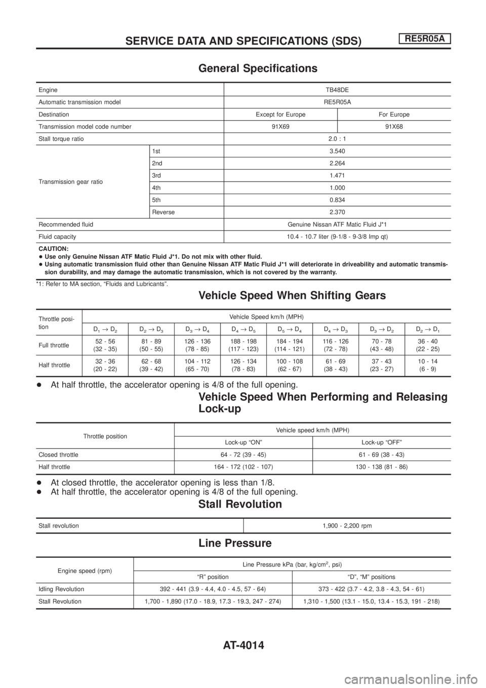
General Speci®cations
EngineTB48DE
Automatic transmission modelRE5R05A
Destination Except for Europe For Europe
Transmission model code number 91X69 91X68
Stall torque ratio2.0:1
Transmission gear ratio1st 3.540
2nd 2.264
3rd 1.471
4th 1.000
5th 0.834
Reverse 2.370
Recommended ¯uid Genuine Nissan ATF Matic Fluid J*1
Fluid capacity10.4 - 10.7 liter (9-1/8 - 9-3/8 Imp qt)
CAUTION:
+Use only Genuine Nissan ATF Matic Fluid J*1. Do not mix with other ¯uid.
+Using automatic transmission ¯uid other than Genuine Nissan ATF Matic Fluid J*1 will deteriorate in driveability and automatic transmis-
sion durability, and may damage the automatic transmission, which is not covered by the warranty.
*1: Refer to MA section, ªFluids and Lubricantsº.
Vehicle Speed When Shifting Gears
Throttle posi-
tionVehicle Speed km/h (MPH)
D
1®D2D2®D3D3®D4D4®D5D5®D4D4®D3D3®D2D2®D1
Full throttle52-56
(32 - 35)81-89
(50 - 55)126 - 136
(78 - 85)188 - 198
(117 - 123)184 - 194
(114 - 121)116 - 126
(72 - 78)70-78
(43 - 48)36-40
(22 - 25)
Half throttle32-36
(20 - 22)62-68
(39 - 42)104 - 112
(65 - 70)126 - 134
(78 - 83)100 - 108
(62 - 67)61-69
(38 - 43)37-43
(23 - 27)10-14
(6-9)
+At half throttle, the accelerator opening is 4/8 of the full opening.
Vehicle Speed When Performing and Releasing
Lock-up
Throttle positionVehicle speed km/h (MPH)
Lock-up ªONº Lock-up ªOFFº
Closed throttle 64 - 72 (39 - 45) 61 - 69 (38 - 43)
Half throttle 164 - 172 (102 - 107) 130 - 138 (81 - 86)
+At closed throttle, the accelerator opening is less than 1/8.
+At half throttle, the accelerator opening is 4/8 of the full opening.
Stall Revolution
Stall revolution1,900 - 2,200 rpm
Line Pressure
Engine speed (rpm)Line Pressure kPa (bar, kg/cm
2, psi)
ªRº position ªDº, ªMº positions
Idling Revolution 392 - 441 (3.9 - 4.4, 4.0 - 4.5, 57 - 64) 373 - 422 (3.7 - 4.2, 3.8 - 4.3, 54 - 61)
Stall Revolution 1,700 - 1,890 (17.0 - 18.9, 17.3 - 19.3, 247 - 274) 1,310 - 1,500 (13.1 - 15.0, 13.4 - 15.3, 191 - 218)
SERVICE DATA AND SPECIFICATIONS (SDS)RE5R05A
AT-4014
Page 20 of 579
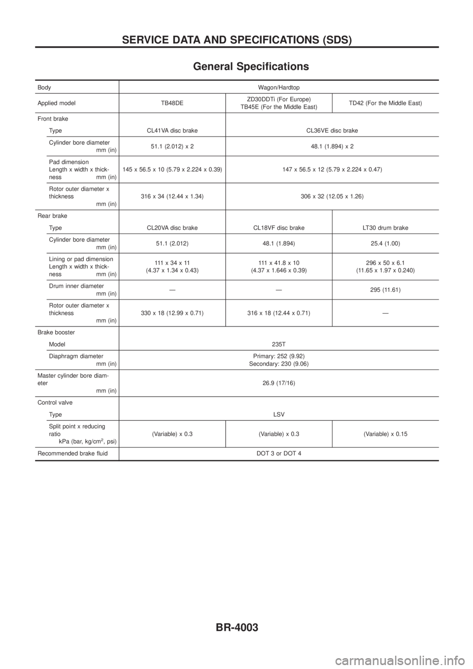
General Speci®cations
BodyWagon/Hardtop
Applied model TB48DEZD30DDTi (For Europe)
TB45E (For the Middle East)TD42 (For the Middle East)
Front brake
Type CL41VA disc brake CL36VE disc brake
Cylinder bore diameter
mm (in)51.1 (2.012) x 2 48.1 (1.894) x 2
Pad dimension
Length x width x thick-
ness mm (in)145 x 56.5 x 10 (5.79 x 2.224 x 0.39) 147 x 56.5 x 12 (5.79 x 2.224 x 0.47)
Rotor outer diameter x
thickness
mm (in)316 x 34 (12.44 x 1.34) 306 x 32 (12.05 x 1.26)
Rear brake
Type CL20VA disc brake CL18VF disc brake LT30 drum brake
Cylinder bore diameter
mm (in)51.1 (2.012) 48.1 (1.894) 25.4 (1.00)
Lining or pad dimension
Length x width x thick-
ness mm (in)111x34x11
(4.37 x 1.34 x 0.43)111x41.8x10
(4.37 x 1.646 x 0.39)296x50x6.1
(11.65 x 1.97 x 0.240)
Drum inner diameter
mm (in)Ð Ð 295 (11.61)
Rotor outer diameter x
thickness
mm (in)330 x 18 (12.99 x 0.71) 316 x 18 (12.44 x 0.71) Ð
Brake booster
Model235T
Diaphragm diameter
mm (in)Primary: 252 (9.92)
Secondary: 230 (9.06)
Master cylinder bore diam-
eter
mm (in)26.9 (17/16)
Control valve
TypeLSV
Split point x reducing
ratio
kPa (bar, kg/cm
2, psi)(Variable) x 0.3 (Variable) x 0.3 (Variable) x 0.15
Recommended brake ¯uid DOT 3 or DOT 4
SERVICE DATA AND SPECIFICATIONS (SDS)
BR-4003
Page 35 of 579
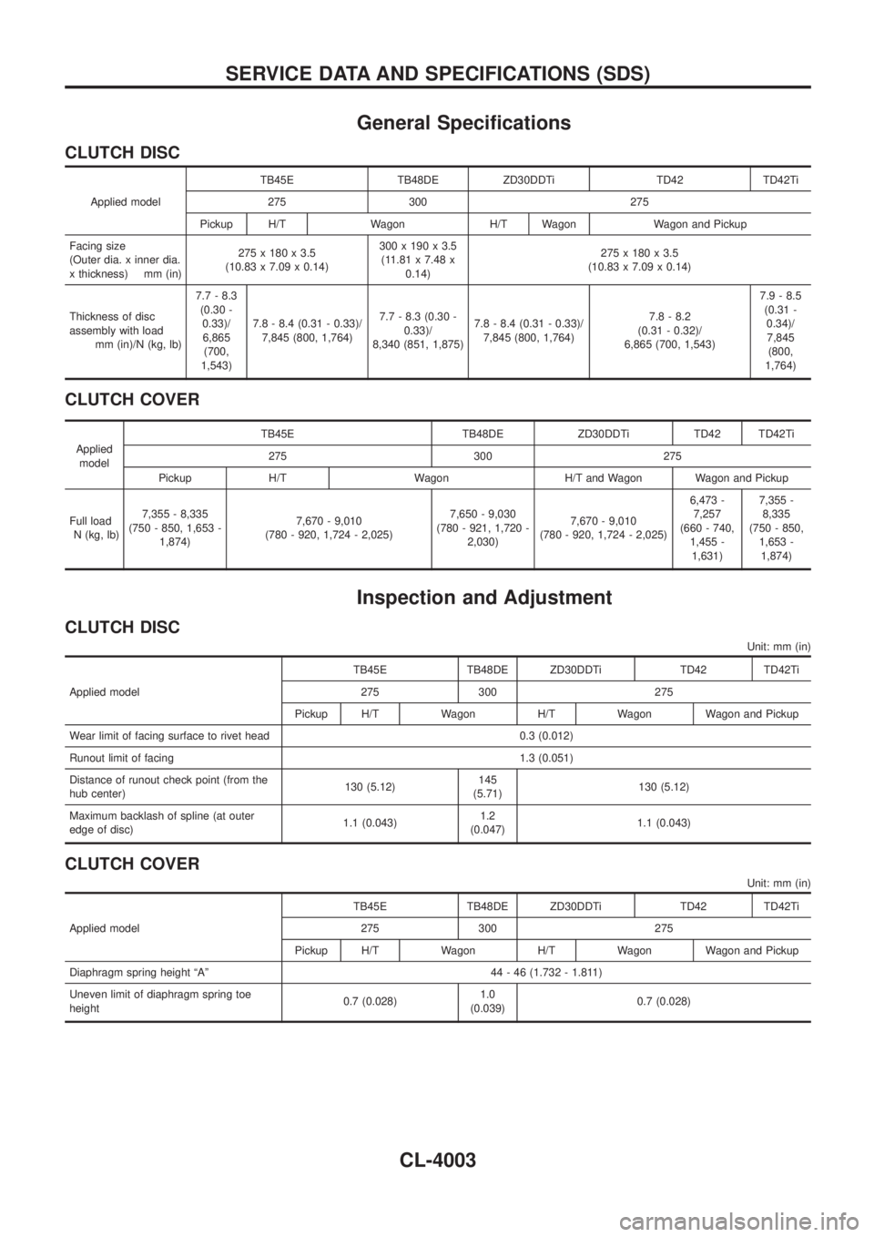
General Speci®cations
CLUTCH DISC
Applied modelTB45E TB48DE ZD30DDTi TD42 TD42Ti
275 300 275
Pickup H/T Wagon H/T Wagon Wagon and Pickup
Facing size
(Outer dia. x inner dia.
x thickness) mm (in)275 x 180 x 3.5
(10.83 x 7.09 x 0.14)300 x 190 x 3.5
(11.81 x 7.48 x
0.14)275 x 180 x 3.5
(10.83 x 7.09 x 0.14)
Thickness of disc
assembly with load
mm (in)/N (kg, lb)7.7 - 8.3
(0.30 -
0.33)/
6,865
(700,
1,543)7.8 - 8.4 (0.31 - 0.33)/
7,845 (800, 1,764)7.7 - 8.3 (0.30 -
0.33)/
8,340 (851, 1,875)7.8 - 8.4 (0.31 - 0.33)/
7,845 (800, 1,764)7.8 - 8.2
(0.31 - 0.32)/
6,865 (700, 1,543)7.9 - 8.5
(0.31 -
0.34)/
7,845
(800,
1,764)
CLUTCH COVER
Applied
modelTB45E TB48DE ZD30DDTi TD42 TD42Ti
275 300 275
Pickup H/T Wagon H/T and Wagon Wagon and Pickup
Full load
N (kg, lb)7,355 - 8,335
(750 - 850, 1,653 -
1,874)7,670 - 9,010
(780 - 920, 1,724 - 2,025)7,650 - 9,030
(780 - 921, 1,720 -
2,030)7,670 - 9,010
(780 - 920, 1,724 - 2,025)6,473 -
7,257
(660 - 740,
1,455 -
1,631)7,355 -
8,335
(750 - 850,
1,653 -
1,874)
Inspection and Adjustment
CLUTCH DISC
Unit: mm (in)
Applied modelTB45E TB48DE ZD30DDTi TD42 TD42Ti
275 300 275
Pickup H/T Wagon H/T Wagon Wagon and Pickup
Wear limit of facing surface to rivet head 0.3 (0.012)
Runout limit of facing 1.3 (0.051)
Distance of runout check point (from the
hub center)130 (5.12)145
(5.71)130 (5.12)
Maximum backlash of spline (at outer
edge of disc)1.1 (0.043)1.2
(0.047)1.1 (0.043)
CLUTCH COVER
Unit: mm (in)
Applied modelTB45E TB48DE ZD30DDTi TD42 TD42Ti
275 300 275
Pickup H/T Wagon H/T Wagon Wagon and Pickup
Diaphragm spring height ªAº 44 - 46 (1.732 - 1.811)
Uneven limit of diaphragm spring toe
height0.7 (0.028)1.0
(0.039)0.7 (0.028)
SERVICE DATA AND SPECIFICATIONS (SDS)
CL-4003
Page 36 of 579
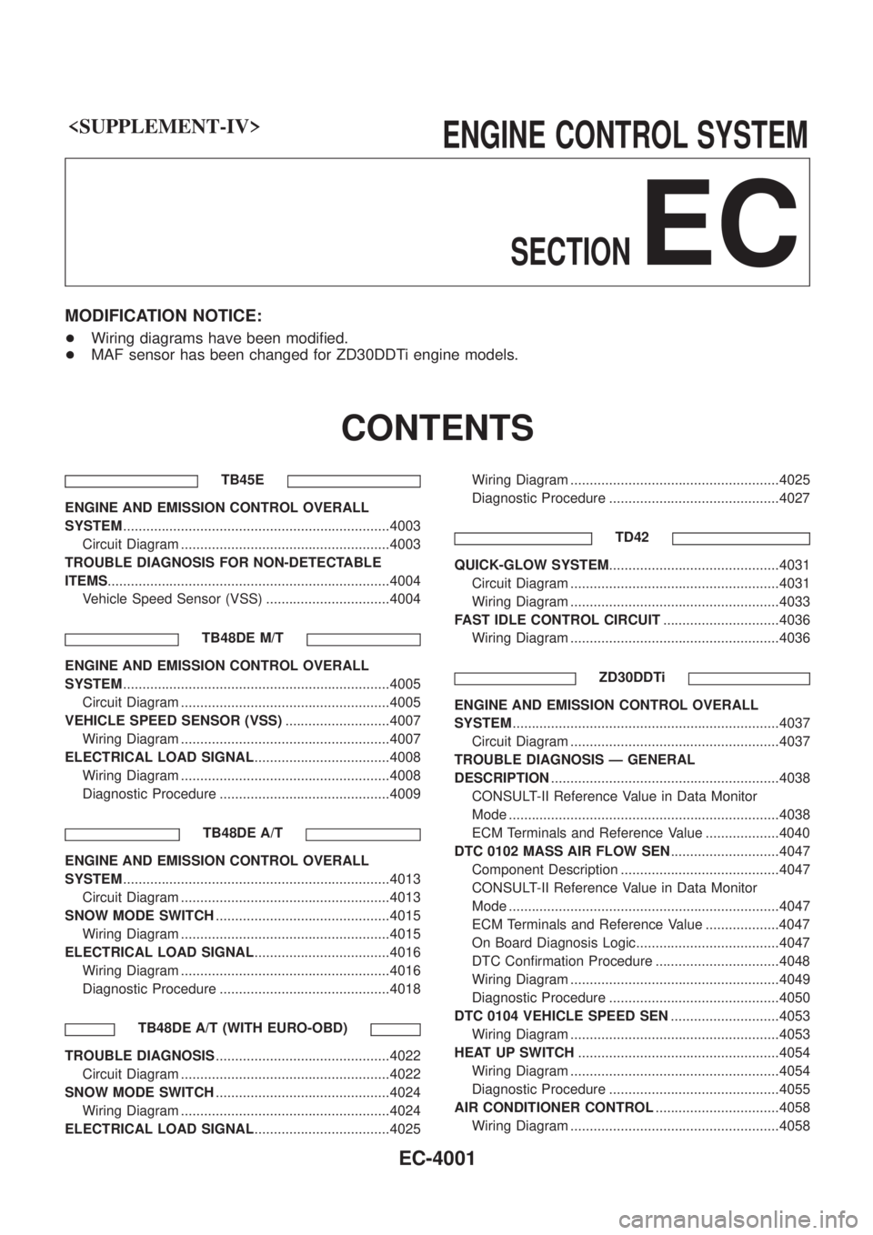
SECTION
EC
MODIFICATION NOTICE:
+Wiring diagrams have been modi®ed.
+ MAF sensor has been changed for ZD30DDTi engine models.
CONTENTS
TB45E
ENGINE AND EMISSION CONTROL OVERALL
SYSTEM .....................................................................4003
Circuit Diagram ......................................................4003
TROUBLE DIAGNOSIS FOR NON-DETECTABLE
ITEMS ........................................................................\
.4004
Vehicle Speed Sensor (VSS) ................................4004
TB48DE M/T
ENGINE AND EMISSION CONTROL OVERALL
SYSTEM.....................................................................4005
Circuit Diagram ......................................................4005
VEHICLE SPEED SENSOR (VSS) ...........................4007
Wiring Diagram ......................................................4007
ELECTRICAL LOAD SIGNAL ...................................4008
Wiring Diagram ......................................................4008
Diagnostic Procedure ............................................4009
TB48DE A/T
ENGINE AND EMISSION CONTROL OVERALL
SYSTEM.....................................................................4013
Circuit Diagram ......................................................4013
SNOW MODE SWITCH .............................................4015
Wiring Diagram ......................................................4015
ELECTRICAL LOAD SIGNAL ...................................4016
Wiring Diagram ......................................................4016
Diagnostic Procedure ............................................4018
TB48DE A/T (WITH EURO-OBD)
TROUBLE DIAGNOSIS .............................................4022
Circuit Diagram ......................................................4022
SNOW MODE SWITCH .............................................4024
Wiring Diagram ......................................................4024
ELECTRICAL LOAD SIGNAL ...................................4025 Wiring Diagram ......................................................4025
Diagnostic Procedure ............................................4027
TD42
QUICK-GLOW SYSTEM ............................................4031
Circuit Diagram ......................................................4031
Wiring Diagram ......................................................4033
FAST IDLE CONTROL CIRCUIT ..............................4036
Wiring Diagram ......................................................4036
ZD30DDTi
ENGINE AND EMISSION CONTROL OVERALL
SYSTEM.....................................................................4037
Circuit Diagram ......................................................4037
TROUBLE DIAGNOSIS Ð GENERAL
DESCRIPTION ...........................................................4038
CONSULT-II Reference Value in Data Monitor
Mode ......................................................................4038
ECM Terminals and Reference Value ...................4040
DTC 0102 MASS AIR FLOW SEN ............................4047
Component Description .........................................4047
CONSULT-II Reference Value in Data Monitor
Mode ......................................................................4047
ECM Terminals and Reference Value ...................4047
On Board Diagnosis Logic.....................................4047
DTC Con®rmation Procedure ................................4048
Wiring Diagram ......................................................4049
Diagnostic Procedure ............................................4050
DTC 0104 VEHICLE SPEED SEN ............................4053
Wiring Diagram ......................................................4053
HEAT UP SWITCH ....................................................4054
Wiring Diagram ......................................................4054
Diagnostic Procedure ............................................4055
AIR CONDITIONER CONTROL ................................4058
Wiring Diagram ......................................................4058
EC-4001
Page 40 of 579
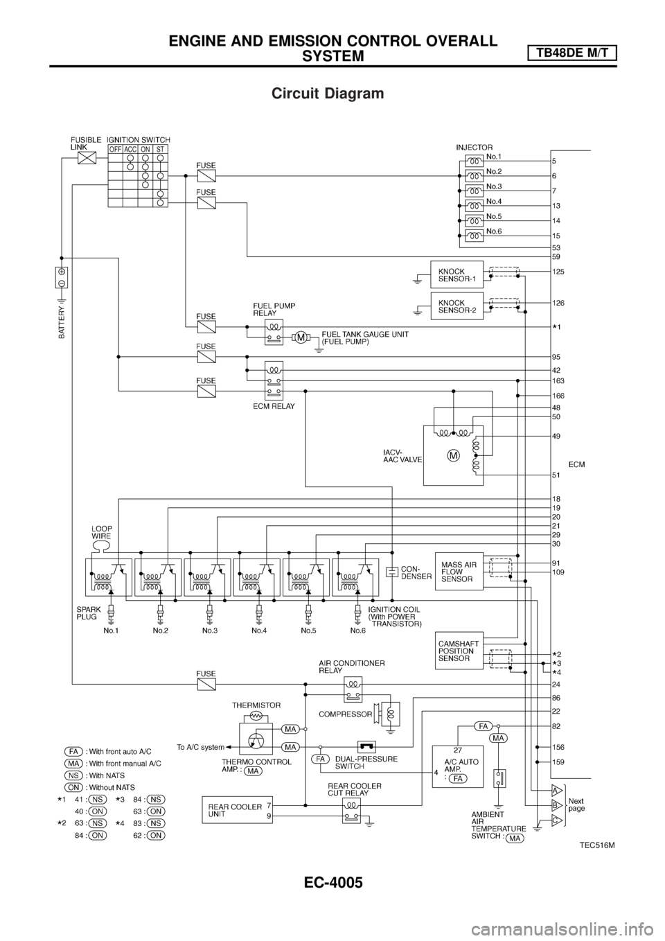
Circuit Diagram
TEC516M
ENGINE AND EMISSION CONTROL OVERALL
SYSTEMTB48DE M/T
EC-4005
Page 41 of 579

TEC533M
ENGINE AND EMISSION CONTROL OVERALL
SYSTEMTB48DE M/T
Circuit Diagram (Cont'd)
EC-4006
Page 42 of 579

Wiring Diagram
TEC534M
VEHICLE SPEED SENSOR (VSS)TB48DE M/T
EC-4007
Page 43 of 579

Wiring Diagram
TEC517M
ELECTRICAL LOAD SIGNALTB48DE M/T
EC-4008
Page 44 of 579

Diagnostic Procedure
INSPECTION START
Do you have CONSULT-II?
Ye s
cNo
Go tojA. (Without CON-
SULT-II)
CHECK OVERALL FUNCTION-I.
With CONSULT-II
1. Turn ignition switch ON.
2. Check ªLOAD SIGNALº in ªDATA
MONITORº mode with CONSULT-II.
Rear window defogger ON
LOAD SIGNAL: ON
Rear window defogger OFF
LOAD SIGNAL: OFF
OK
cNG
Check rear window defog-
ger circuit. (Go toj
B.)
CHECK OVERALL FUNCTION-II.
With CONSULT-II
Check ªLOAD SIGNALº in ªDATA MONI-
TORº mode with CONSULT-II.
Lighting switch ON at 2nd position
LOAD SIGNAL: ON
Lighting switch OFF
LOAD SIGNAL: OFF
OK
cNG
Check lighting switch cir-
cuit. (Go toj
C.)
INSPECTION END
PBIB0103E
PBIB0296E
PBIB0103E
PBIB0296E
.
.
.
.
ELECTRICAL LOAD SIGNALTB48DE M/T
EC-4009
Page 45 of 579

jA
CHECK OVERALL FUNCTION-I.
Without CONSULT-II
1. Turn ignition switch ON.
2. Check voltage between ECM terminal
j
96and ground with tester.
Rear window defogger ON
Voltage: Battery voltage
Rear window defogger OFF
Voltage: 0V
OK
cNG
Check rear window defog-
ger circuit. (Go toj
B.)
CHECK OVERALL FUNCTION-II.
Without CONSULT-II
Check voltage between ECM terminalj
97
and ground with tester.
Lighting switch ON at 2nd position
Voltage: Battery voltage
Lighting switch OFF
Voltage: 0V
OK
cNG
Check lighting switch cir-
cuit. (Go toj
C.)
INSPECTION END
SEC022E
SEC010E
.
.
.
ELECTRICAL LOAD SIGNALTB48DE M/T
Diagnostic Procedure (Cont'd)
EC-4010