Throttle NISSAN PATROL 2004 Electronic Repair Manual
[x] Cancel search | Manufacturer: NISSAN, Model Year: 2004, Model line: PATROL, Model: NISSAN PATROL 2004Pages: 579, PDF Size: 26.61 MB
Page 16 of 579
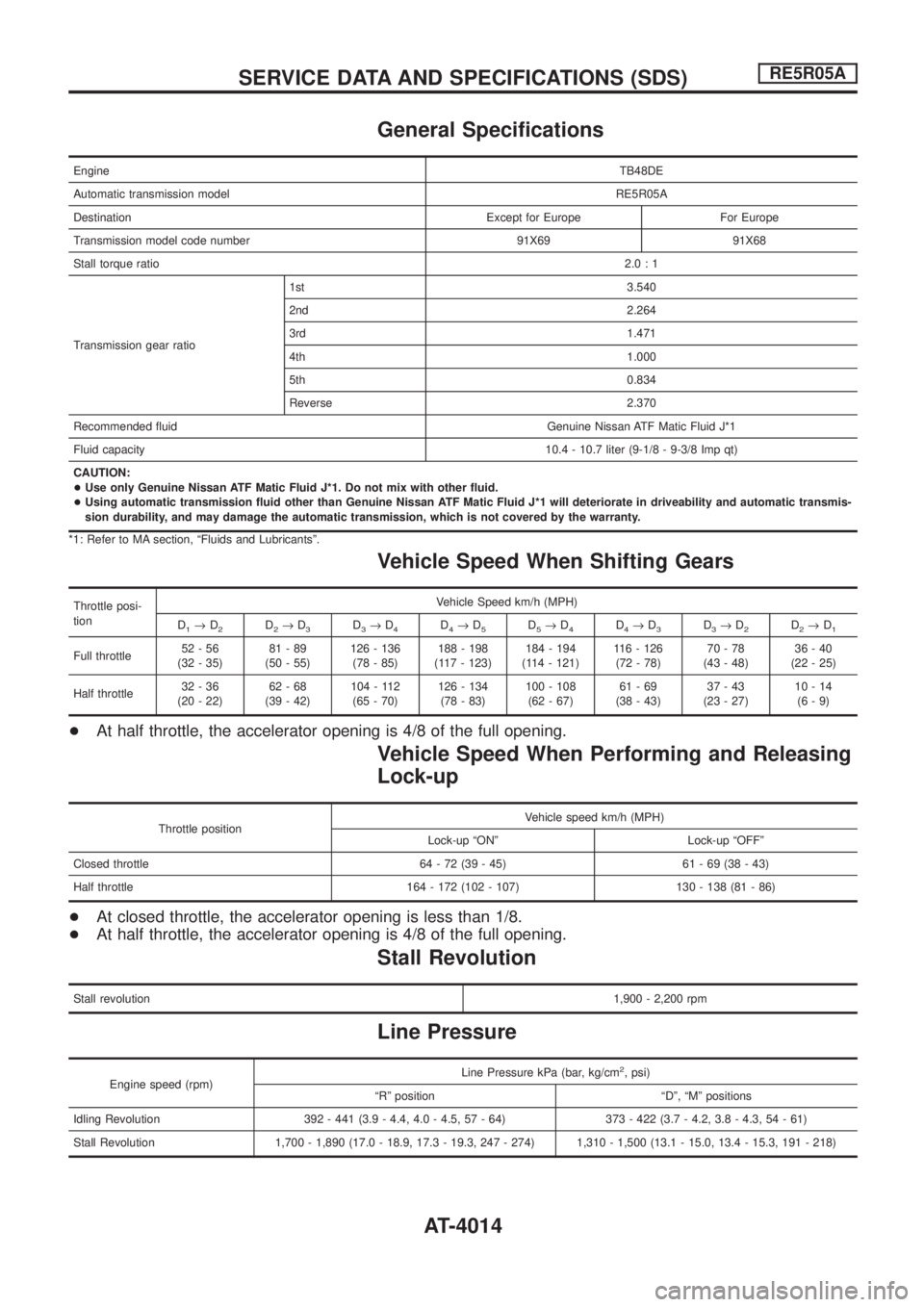
General Speci®cations
EngineTB48DE
Automatic transmission modelRE5R05A
Destination Except for Europe For Europe
Transmission model code number 91X69 91X68
Stall torque ratio2.0:1
Transmission gear ratio1st 3.540
2nd 2.264
3rd 1.471
4th 1.000
5th 0.834
Reverse 2.370
Recommended ¯uid Genuine Nissan ATF Matic Fluid J*1
Fluid capacity10.4 - 10.7 liter (9-1/8 - 9-3/8 Imp qt)
CAUTION:
+Use only Genuine Nissan ATF Matic Fluid J*1. Do not mix with other ¯uid.
+Using automatic transmission ¯uid other than Genuine Nissan ATF Matic Fluid J*1 will deteriorate in driveability and automatic transmis-
sion durability, and may damage the automatic transmission, which is not covered by the warranty.
*1: Refer to MA section, ªFluids and Lubricantsº.
Vehicle Speed When Shifting Gears
Throttle posi-
tionVehicle Speed km/h (MPH)
D
1®D2D2®D3D3®D4D4®D5D5®D4D4®D3D3®D2D2®D1
Full throttle52-56
(32 - 35)81-89
(50 - 55)126 - 136
(78 - 85)188 - 198
(117 - 123)184 - 194
(114 - 121)116 - 126
(72 - 78)70-78
(43 - 48)36-40
(22 - 25)
Half throttle32-36
(20 - 22)62-68
(39 - 42)104 - 112
(65 - 70)126 - 134
(78 - 83)100 - 108
(62 - 67)61-69
(38 - 43)37-43
(23 - 27)10-14
(6-9)
+At half throttle, the accelerator opening is 4/8 of the full opening.
Vehicle Speed When Performing and Releasing
Lock-up
Throttle positionVehicle speed km/h (MPH)
Lock-up ªONº Lock-up ªOFFº
Closed throttle 64 - 72 (39 - 45) 61 - 69 (38 - 43)
Half throttle 164 - 172 (102 - 107) 130 - 138 (81 - 86)
+At closed throttle, the accelerator opening is less than 1/8.
+At half throttle, the accelerator opening is 4/8 of the full opening.
Stall Revolution
Stall revolution1,900 - 2,200 rpm
Line Pressure
Engine speed (rpm)Line Pressure kPa (bar, kg/cm
2, psi)
ªRº position ªDº, ªMº positions
Idling Revolution 392 - 441 (3.9 - 4.4, 4.0 - 4.5, 57 - 64) 373 - 422 (3.7 - 4.2, 3.8 - 4.3, 54 - 61)
Stall Revolution 1,700 - 1,890 (17.0 - 18.9, 17.3 - 19.3, 247 - 274) 1,310 - 1,500 (13.1 - 15.0, 13.4 - 15.3, 191 - 218)
SERVICE DATA AND SPECIFICATIONS (SDS)RE5R05A
AT-4014
Page 17 of 579
Solenoid Valves
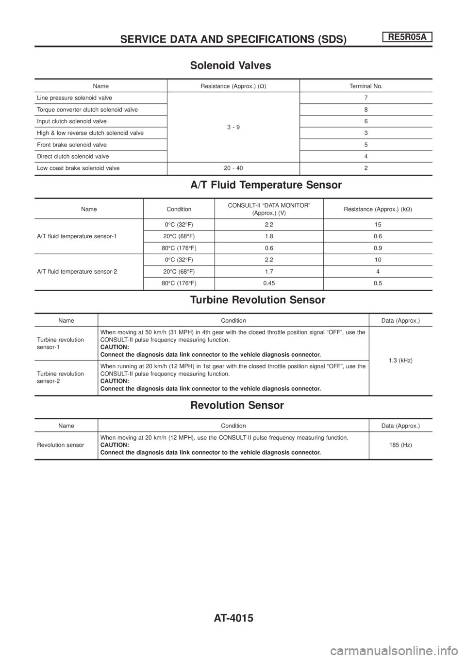
Name Resistance (Approx.) (W) Terminal No.
Line pressure solenoid valve
3-97
Torque converter clutch solenoid valve8
Input clutch solenoid valve6
High & low reverse clutch solenoid valve3
Front brake solenoid valve5
Direct clutch solenoid valve4
Low coast brake solenoid valve 20 - 40 2
A/T Fluid Temperature Sensor
Name ConditionCONSULT-II ªDATA MONITORº
(Approx.) (V)Resistance (Approx.) (kW)
A/T ¯uid temperature sensor-10ÉC (32ÉF) 2.2 15
20ÉC (68ÉF) 1.8 0.6
80ÉC (176ÉF) 0.6 0.9
A/T ¯uid temperature sensor-20ÉC (32ÉF) 2.2 10
20ÉC (68ÉF) 1.7 4
80ÉC (176ÉF) 0.45 0.5
Turbine Revolution Sensor
Name Condition Data (Approx.)
Turbine revolution
sensor-1When moving at 50 km/h (31 MPH) in 4th gear with the closed throttle position signal ªOFFº, use the
CONSULT-II pulse frequency measuring function.
CAUTION:
Connect the diagnosis data link connector to the vehicle diagnosis connector.
1.3 (kHz)
Turbine revolution
sensor-2When running at 20 km/h (12 MPH) in 1st gear with the closed throttle position signal ªOFFº, use the
CONSULT-II pulse frequency measuring function.
CAUTION:
Connect the diagnosis data link connector to the vehicle diagnosis connector.
Revolution Sensor
Name Condition Data (Approx.)
Revolution sensorWhen moving at 20 km/h (12 MPH), use the CONSULT-II pulse frequency measuring function.
CAUTION:
Connect the diagnosis data link connector to the vehicle diagnosis connector.185 (Hz)
SERVICE DATA AND SPECIFICATIONS (SDS)RE5R05A
AT-4015
Page 451 of 579
Removal
1. Remove the following parts.
+Undercover
+Engine oil (Drain)
+Engine coolant (Drain)
+Engine cover
+Intercooler
+Air inlet pipe
+Air cleaner case
+Throttle body
+Swirl and intake air control valve control solenoid valve and
bracket
+Vacuum tank
+Glow plate
+Rocker cover
+Spill tube
+Radiator shrouds (Rear and Lower)
+Cooling fan
+Radiator hose (Upper and Lower)
+Auxiliary belt and auto tensioner.
2. Remove the alternator.
3. Remove the A/C compressor and bracket with piping con-
nected. Move and support it at the LH side of engine bay with
a rope to avoid putting load on piping.
Refer to HA section in NISSAN Service Manual (Publication No.
SM9E-Y61CG2 or SM9E-Y61CG3).
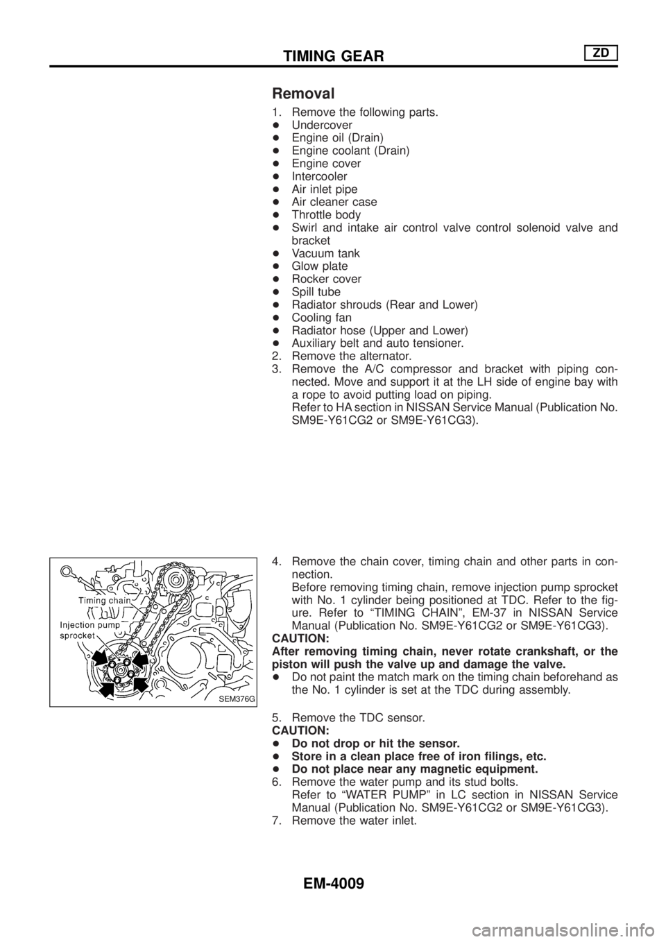
4. Remove the chain cover, timing chain and other parts in con-
nection.
Before removing timing chain, remove injection pump sprocket
with No. 1 cylinder being positioned at TDC. Refer to the ®g-
ure. Refer to ªTIMING CHAINº, EM-37 in NISSAN Service
Manual (Publication No. SM9E-Y61CG2 or SM9E-Y61CG3).
CAUTION:
After removing timing chain, never rotate crankshaft, or the
piston will push the valve up and damage the valve.
+Do not paint the match mark on the timing chain beforehand as
the No. 1 cylinder is set at the TDC during assembly.
5. Remove the TDC sensor.
CAUTION:
+Do not drop or hit the sensor.
+Store in a clean place free of iron ®lings, etc.
+Do not place near any magnetic equipment.
6. Remove the water pump and its stud bolts.
Refer to ªWATER PUMPº in LC section in NISSAN Service
Manual (Publication No. SM9E-Y61CG2 or SM9E-Y61CG3).
7. Remove the water inlet.
SEM376G
TIMING GEARZD
EM-4009
Page 481 of 579
Features (TB48 Engine Models)
CAN COMMUNICATION SYSTEM DESCRIPTION
CAN (Controller Area Network) is a serial communication line for real time application. It is an on-vehicle mul-
tiplex communication line with high data communication speed and excellent error detection ability. Many
electronic control units are equipped onto a vehicle, and each control unit shares information and links with
other control units during operation (not independent). In CAN communication, control units are connected with
2 communication lines (CAN H line, CAN L line) allowing a high rate of information transmission with less wir-
ing. Each control unit transmits/receives data but selectively reads required data only.
SYSTEM CONSTRUCTION
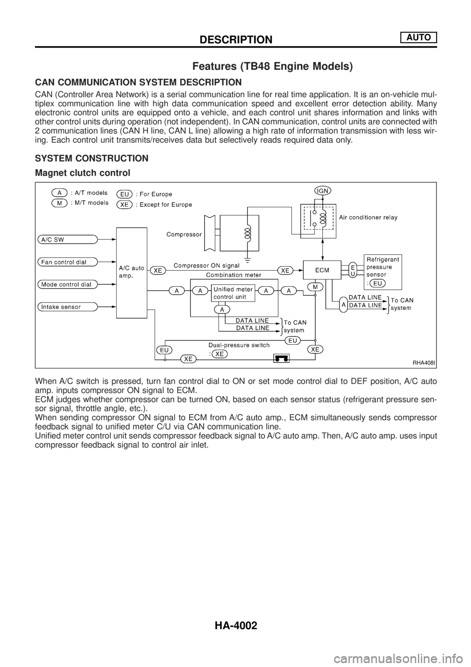
Magnet clutch control
When A/C switch is pressed, turn fan control dial to ON or set mode control dial to DEF position, A/C auto
amp. inputs compressor ON signal to ECM.
ECM judges whether compressor can be turned ON, based on each sensor status (refrigerant pressure sen-
sor signal, throttle angle, etc.).
When sending compressor ON signal to ECM from A/C auto amp., ECM simultaneously sends compressor
feedback signal to uni®ed meter C/U via CAN communication line.
Uni®ed meter control unit sends compressor feedback signal to A/C auto amp. Then, A/C auto amp. uses input
compressor feedback signal to control air inlet.
RHA408I
DESCRIPTIONAUTO
HA-4002