Transmission model NISSAN PATROL 2004 Electronic Repair Manual
[x] Cancel search | Manufacturer: NISSAN, Model Year: 2004, Model line: PATROL, Model: NISSAN PATROL 2004Pages: 579, PDF Size: 26.61 MB
Page 1 of 579
Edition: July 2004
Release: July 2004 (01)
Publication No.: SM4E00-1Y61E0E
Reference No.: 7711347233GENERAL INFORMATIONGI
MAINTENANCEMA
ENGINE MECHANICALEM
ENGINE LUBRICATION &
COOLING SYSTEMSLC
ENGINE CONTROL SYSTEMEC
ACCELERATOR CONTROL,
FUEL & EXHAUST SYSTEMFE
CLUTCHCL
MANUAL TRANSMISSIONMT
AUTOMATIC TRANSMISSIONAT
TRANSFERTF
PROPELLER SHAFT &
DIFFERENTIAL CARRIERPD
FRONT AXLE & FRONT SUSPENSIONFA
REAR AXLE & REAR SUSPENSIONRA
BRAKE SYSTEMBR
STEERING SYSTEMST
RESTRAINT SYSTEMRS
BODY & TRIMBT
HEATER & AIR CONDITIONERHA
ELECTRICAL SYSTEMEL
ALPHABETICAL INDEXIDX
PATROL
MODEL Y61 SERIES
NISSAN EUROPE S.A.S.
2004 NISSAN EUROPE S.A.S.
Produced in The Netherlands
Not to be reproduced in whole or in part
without the prior written permission of
Nissan Europe S.A.S., Paris, France.
QUICK REFERENCE INDEX
Page 16 of 579
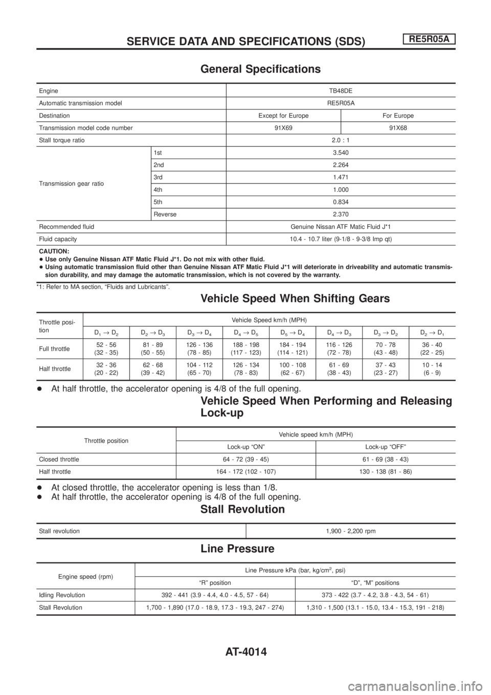
General Speci®cations
EngineTB48DE
Automatic transmission modelRE5R05A
Destination Except for Europe For Europe
Transmission model code number 91X69 91X68
Stall torque ratio2.0:1
Transmission gear ratio1st 3.540
2nd 2.264
3rd 1.471
4th 1.000
5th 0.834
Reverse 2.370
Recommended ¯uid Genuine Nissan ATF Matic Fluid J*1
Fluid capacity10.4 - 10.7 liter (9-1/8 - 9-3/8 Imp qt)
CAUTION:
+Use only Genuine Nissan ATF Matic Fluid J*1. Do not mix with other ¯uid.
+Using automatic transmission ¯uid other than Genuine Nissan ATF Matic Fluid J*1 will deteriorate in driveability and automatic transmis-
sion durability, and may damage the automatic transmission, which is not covered by the warranty.
*1: Refer to MA section, ªFluids and Lubricantsº.
Vehicle Speed When Shifting Gears
Throttle posi-
tionVehicle Speed km/h (MPH)
D
1®D2D2®D3D3®D4D4®D5D5®D4D4®D3D3®D2D2®D1
Full throttle52-56
(32 - 35)81-89
(50 - 55)126 - 136
(78 - 85)188 - 198
(117 - 123)184 - 194
(114 - 121)116 - 126
(72 - 78)70-78
(43 - 48)36-40
(22 - 25)
Half throttle32-36
(20 - 22)62-68
(39 - 42)104 - 112
(65 - 70)126 - 134
(78 - 83)100 - 108
(62 - 67)61-69
(38 - 43)37-43
(23 - 27)10-14
(6-9)
+At half throttle, the accelerator opening is 4/8 of the full opening.
Vehicle Speed When Performing and Releasing
Lock-up
Throttle positionVehicle speed km/h (MPH)
Lock-up ªONº Lock-up ªOFFº
Closed throttle 64 - 72 (39 - 45) 61 - 69 (38 - 43)
Half throttle 164 - 172 (102 - 107) 130 - 138 (81 - 86)
+At closed throttle, the accelerator opening is less than 1/8.
+At half throttle, the accelerator opening is 4/8 of the full opening.
Stall Revolution
Stall revolution1,900 - 2,200 rpm
Line Pressure
Engine speed (rpm)Line Pressure kPa (bar, kg/cm
2, psi)
ªRº position ªDº, ªMº positions
Idling Revolution 392 - 441 (3.9 - 4.4, 4.0 - 4.5, 57 - 64) 373 - 422 (3.7 - 4.2, 3.8 - 4.3, 54 - 61)
Stall Revolution 1,700 - 1,890 (17.0 - 18.9, 17.3 - 19.3, 247 - 274) 1,310 - 1,500 (13.1 - 15.0, 13.4 - 15.3, 191 - 218)
SERVICE DATA AND SPECIFICATIONS (SDS)RE5R05A
AT-4014
Page 471 of 579
GI
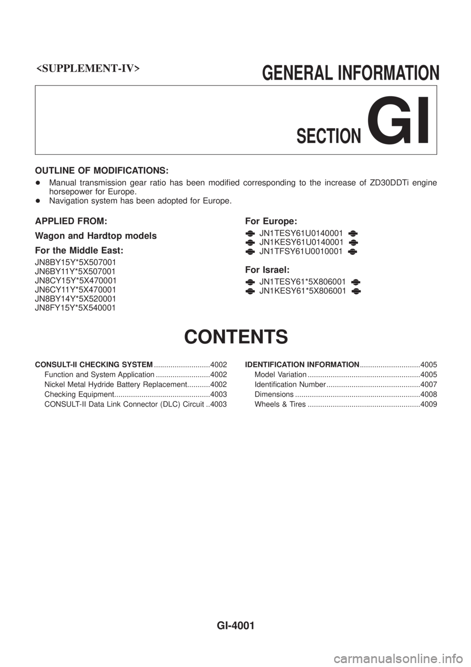
OUTLINE OF MODIFICATIONS:
+Manual transmission gear ratio has been modi®ed corresponding to the increase of ZD30DDTi engine
horsepower for Europe.
+ Navigation system has been adopted for Europe.
APPLIED FROM:
Wagon and Hardtop models
For the Middle East:
JN8BY15Y*5X507001
JN6BY11Y*5X507001
JN8CY15Y*5X470001
JN6CY11Y*5X470001
JN8BY14Y*5X520001
JN8FY15Y*5X540001
For Europe:
JN1TESY61U0140001
JN1KESY61U0140001
JN1TFSY61U0010001
For Israel:
JN1TESY61*5X806001
JN1KESY61*5X806001
CONTENTS
CONSULT-II CHECKING SYSTEM ...........................4002
Function and System Application ..........................4002
Nickel Metal Hydride Battery Replacement...........4002
Checking Equipment..............................................4003
CONSULT-II Data Link Connector (DLC) Circuit ..4003 IDENTIFICATION INFORMATION
.............................4005
Model Variation ......................................................4005
Identi®cation Number .............................................4007
Dimensions ............................................................4008
Wheels & Tires ......................................................4009
GI-4001
Page 476 of 579
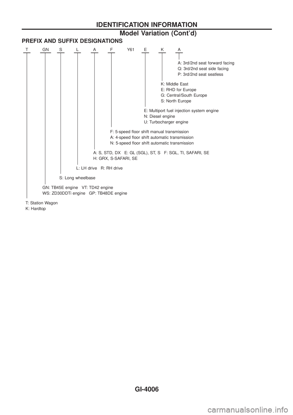
PREFIX AND SUFFIX DESIGNATIONS
TGNSLAFY61 EKA
A: 3rd/2nd seat forward facing
Q: 3rd/2nd seat side facing
P: 3rd/2nd seat seatless
K: Middle East
E: RHD for Europe
G: Central/South Europe
S: North Europe
E: Multiport fuel injection system engine
N: Diesel engine
U: Turbocharger engine
F: 5-speed ¯oor shift manual transmission
A: 4-speed ¯oor shift automatic transmission
N: 5-speed ¯oor shift automatic transmission
A: S, STD, DX E: GL (SGL), ST, S F: SGL, TI, SAFARI, SE
H: GRX, S-SAFARI, SE
L: LH drive R: RH drive
S: Long wheelbase
GN: TB45E engine VT: TD42 engine
WS: ZD30DDTi engine GP: TB48DE engine
T: Station Wagon
K: Hardtop
IDENTIFICATION INFORMATION
Model Variation (Cont'd)
GI-4006
Page 481 of 579
Features (TB48 Engine Models)
CAN COMMUNICATION SYSTEM DESCRIPTION
CAN (Controller Area Network) is a serial communication line for real time application. It is an on-vehicle mul-
tiplex communication line with high data communication speed and excellent error detection ability. Many
electronic control units are equipped onto a vehicle, and each control unit shares information and links with
other control units during operation (not independent). In CAN communication, control units are connected with
2 communication lines (CAN H line, CAN L line) allowing a high rate of information transmission with less wir-
ing. Each control unit transmits/receives data but selectively reads required data only.
SYSTEM CONSTRUCTION
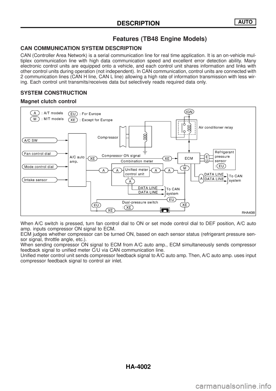
Magnet clutch control
When A/C switch is pressed, turn fan control dial to ON or set mode control dial to DEF position, A/C auto
amp. inputs compressor ON signal to ECM.
ECM judges whether compressor can be turned ON, based on each sensor status (refrigerant pressure sen-
sor signal, throttle angle, etc.).
When sending compressor ON signal to ECM from A/C auto amp., ECM simultaneously sends compressor
feedback signal to uni®ed meter C/U via CAN communication line.
Uni®ed meter control unit sends compressor feedback signal to A/C auto amp. Then, A/C auto amp. uses input
compressor feedback signal to control air inlet.
RHA408I
DESCRIPTIONAUTO
HA-4002
Page 554 of 579

General Speci®cations
Applied modelTB45E TB48DE ZD30DDTi TD42 TD42Ti
Pickup Hardtop Wagon Hardtop Wagon Wagon & Pickup
4WD
TransmissionFS5R50B
Number of speed5
Transmission control Floor direct
Shift pattern
Synchromesh type Warner
Gear ratio
1st 4.262 4.084 4.556 4.262
2nd 2.455 2.353 2.625 2.455
3rd 1.488 1.426 1.591 1.488
4th 1.000 1.000 1.000 1.000
OD 0.850 0.880 0.836 0.850
Reverse 3.971 3.806 4.245 3.971
Number of teeth
Mainshaft
Drive 27 29 26 27
1st 44 44 44 44
2nd 39 39 39 39
3rd 39 39 39 39
OD 25 27 23 25
Reverse 41 41 41 41
Countershaft
Drive 34 35 35 34
1st 13 13 13 13
2nd 20 20 20 20
3rd 33 33 33 33
OD 37 37 37 37
Reverse 13 13 13 13
Reverse idler gear 27
Oil capacity!(Imp pt) 3.5 (6-1/8)
Remarks1st, 2nd and 3rd double baulk ring type synchronizer
Reverse synchronizer type
SERVICE DATA AND SPECIFICATIONSFS5R50B
MT-4002