communication line NISSAN PATROL 2004 Electronic Repair Manual
[x] Cancel search | Manufacturer: NISSAN, Model Year: 2004, Model line: PATROL, Model: NISSAN PATROL 2004Pages: 579, PDF Size: 26.61 MB
Page 285 of 579
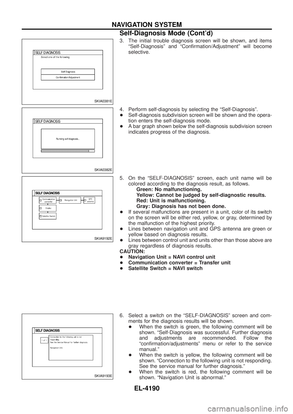
3. The initial trouble diagnosis screen will be shown, and itemsªSelf-Diagnosisº and ªCon®rmation/Adjustmentº will become
selective.
4. Perform self-diagnosis by selecting the ªSelf-Diagnosisº.
+ Self-diagnosis subdivision screen will be shown and the opera-
tion enters the self-diagnosis mode.
+ A bar graph shown below the self-diagnosis subdivision screen
indicates progress of the diagnosis.
5. On the ªSELF-DIAGNOSISº screen, each unit name will be colored according to the diagnosis result, as follows.Green: No malfunctioning.
Yellow: Cannot be judged by self-diagnostic results.
Red: Unit is malfunctioning.
Gray: Diagnosis has not been done.
+ If several malfunctions are present in a unit, color of its switch
on the screen will be either red, yellow, or gray, determined by
the malfunction of the highest priority.
+ Lines between navigation unit and GPS antenna are green or
yellow based on diagnosis results.
+ Lines between control unit and units other than those above are
gray regardless of diagnosis results.
CAUTION:
+ Navigation Unit = NAVI control unit
+ Communication converter = Transfer unit
+ Satellite Switch = NAVI switch
6. Select a switch on the ªSELF-DIAGNOSISº screen and com- ments for the diagnosis results will be shown.
+ When the switch is green, the following comment will be
shown. ªSelf-Diagnosis was successful. Further diagnosis
and adjustments are recommended. Follow the
ªcon®rmation/adjustmentsº menu or refer to the service
manual.º
+ When the switch is yellow, the following comment will be
shown. ªConnection to the following unit is not responding.
See the service manual for further diagnosis.º
+ When the switch is red, the following comment will be
shown. ªNavigation Unit is abnormal.º
SKIA0381E
SKIA0382E
SKIA9192E
SKIA9193E
NAVIGATION SYSTEM
Self-Diagnosis Mode (Cont'd)
EL-4190
Page 286 of 579
+When the switch is gray, the following comment will be
shown. ªSelf-diagnosis for DVD-ROM DRIVER of NAVI
was not conducted due to no insertion of DVD-ROM.º
SELF-DIAGNOSIS RESULT
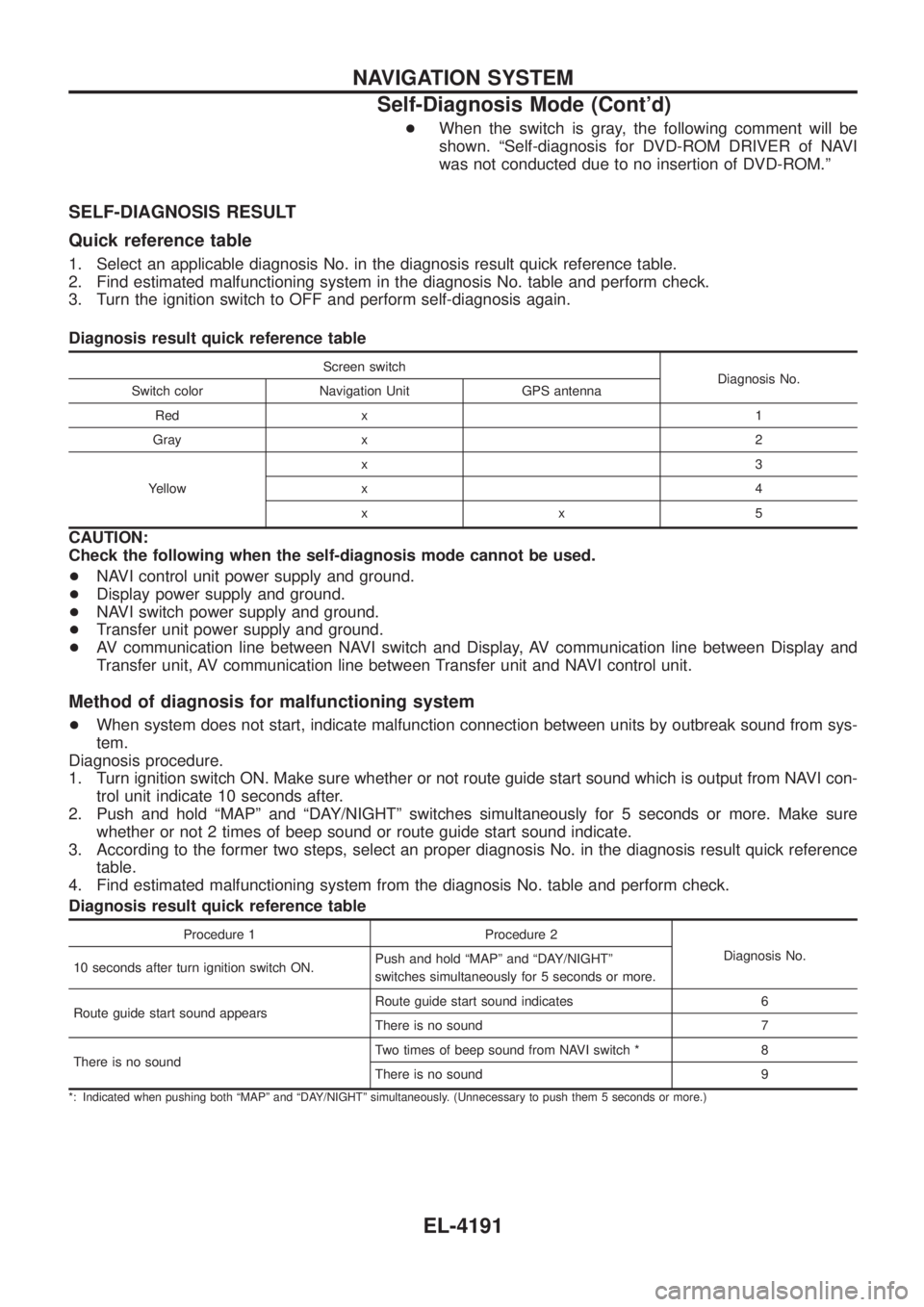
Quick reference table
1. Select an applicable diagnosis No. in the diagnosis result quick reference table.
2. Find estimated malfunctioning system in the diagnosis No. table and perform check.
3. Turn the ignition switch to OFF and perform self-diagnosis again.
Diagnosis result quick reference table
Screen switch
Diagnosis No.
Switch color Navigation Unit GPS antenna
Red x 1
Gray x 2
Yellow x3
x4
xx5
CAUTION:
Check the following when the self-diagnosis mode cannot be used.
+
NAVI control unit power supply and ground.
+ Display power supply and ground.
+ NAVI switch power supply and ground.
+ Transfer unit power supply and ground.
+ AV communication line between NAVI switch and Display, AV communication line between Display and
Transfer unit, AV communication line between Transfer unit and NAVI control unit.
Method of diagnosis for malfunctioning system
+When system does not start, indicate malfunction connection between units by outbreak sound from sys-
tem.
Diagnosis procedure.
1. Turn ignition switch ON. Make sure whether or not route guide start sound which is output from NAVI con- trol unit indicate 10 seconds after.
2. Push and hold ªMAPº and ªDAY/NIGHTº switches simultaneously for 5 seconds or more. Make sure whether or not 2 times of beep sound or route guide start sound indicate.
3. According to the former two steps, select an proper diagnosis No. in the diagnosis result quick reference table.
4. Find estimated malfunctioning system from the diagnosis No. table and perform check.
Diagnosis result quick reference table
Procedure 1 Procedure 2
Diagnosis No.
10 seconds after turn ignition switch ON. Push and hold ªMAPº and ªDAY/NIGHTº
switches simultaneously for 5 seconds or more.
Route guide start sound appears Route guide start sound indicates 6
There is no sound 7
There is no sound Two times of beep sound from NAVI switch * 8
There is no sound 9
*: Indicated when pushing both ªMAPº and ªDAY/NIGHTº simultaneously. (Unnecessary to push them 5 seconds or more.)
NAVIGATION SYSTEM
Self-Diagnosis Mode (Cont'd)
EL-4191
Page 287 of 579
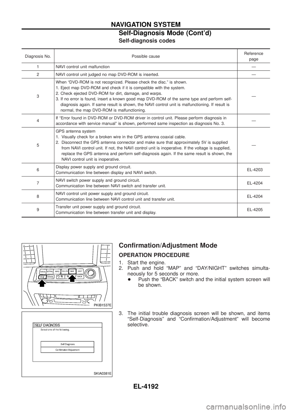
Self-diagnosis codes
Diagnosis No. Possible causeReference
page
1 NAVI control unit malfunction Ð
2 NAVI control unit judged no map DVD-ROM is inserted. Ð
3 When ªDVD-ROM is not recognized. Please check the disc.º is shown.
1. Eject map DVD-ROM and check if it is compatible with the system.
2. Check ejected DVD-ROM for dirt, damage, and warps.
3. If no error is found, insert a known good map DVD-ROM of the same type and perform self-
diagnosis again. If same result is shown, the NAVI control unit is malfunctioning. If result is
normal, the map DVD-ROM is malfunctioning. Ð
4 If ªError found in DVD-ROM or DVD-ROM driver in control unit. Please perform diagnosis in
accordance with service manualº is shown, performed same inspection as diagnosis No. 3. Ð
5 GPS antenna system
1. Visually check for a broken wire in the GPS antenna coaxial cable.
2. Disconnect the GPS antenna connector and make sure that approximately 5V is supplied
from NAVI control unit. If not, the NAVI control unit is inoperative. If the voltage is supplied,
replace the GPS antenna and perform self-diagnosis again. If the same result is shown, the
NAVI control unit is inoperative. Ð
6 Display power supply and ground circuit.
Communication line between display and NAVI switch. EL-4203
7 NAVI switch power supply and ground circuit.
Communication line between NAVI switch and transfer unit. EL-4204
8 NAVI control unit power supply and ground circuit.
Communication line between NAVI control unit and transfer unit. EL-4204
9 Transfer unit power supply and ground circuit.
Communication line between transfer unit and display. EL-4205
Con®rmation/Adjustment Mode
OPERATION PROCEDURE
1. Start the engine.
2. Push and hold ªMAPº and ªDAY/NIGHTº switches simulta-
neously for 5 seconds or more.
+ Push the ªBACKº switch and the initial system screen will
be shown.
3. The initial trouble diagnosis screen will be shown, and items ªSelf-Diagnosisº and ªCon®rmation/Adjustmentº will become
selective.
PKIB1537E
SKIA0381E
NAVIGATION SYSTEM
Self-Diagnosis Mode (Cont'd)
EL-4192
Page 291 of 579
DIAGNOSIS BY HISTORY OF ERRORS
The ªSelf-diagnosisº results indicate whether an error occurred during the period from when the ignition switch
is turned to ON until ªSelf-diagnosisº is completed.
If an error occurred before the ignition switch was turned to ON and does not occur again until the ªSelf-di-
agnosisº is completed, the diagnosis result will be judged normal. Therefore, those errors in the past, which
cannot be found by the ªSelf-diagnosisº, must be found by diagnosing the ªHistory of Errorsº.
The History of Errors displays the time and place of the most recent occurrence of that error. However, take
note of the following points.
+Correct time of the error occurrence may not be displayed when the GPS antenna substrate within the
NAVI control unit has malfunctioned.
+ Place of the error occurrence is represented by the position of the current location mark at the time when
the error occurred. If the current location mark has deviated from the correct position, then the place of
the error occurrence may be located correctly.
+ The maximum number of occurrences which can be stored is 50. For the 51st and later occurrences, the
displayed number remains 50.
When a reproducible malfunction occurred but its cause cannot be identi®ed because several errors are
present, record the item, number and place (longitude/latitude) of error occurrence (or delete the History of
Errors), then turn the ignition switch from OFF to ON to reproduce the malfunction. Check the History of Errors
to ®nd the items which show an increased number of occurrences, and diagnose the item.
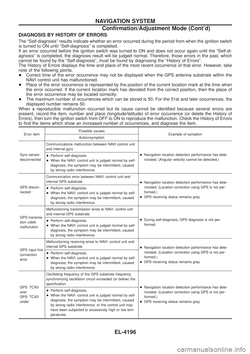
Error item Possible causes
Example of symptom
Action/symptom
Gyro sensor
disconnected Communications malfunction between NAVI control unit
and internal gyro
+Navigation location detection performance has dete-
riorated. (Angular velocity cannot be detected.)
+
Perform self-diagnosis.
+ When the NAVI control unit is judged normal by self-
diagnosis, the symptom may be intermittent, caused
by strong radio interference.
GPS discon-
nected Communication error between NAVI control unit and
internal GPS substrate
+Navigation location detection performance has dete-
riorated. (Location correction using GPS is not per-
formed.)
+ GPS receiving status remains gray.
+
Perform self-diagnosis.
+ When the NAVI control unit is judged normal by self-
diagnosis, the symptom may be intermittent, caused
by strong radio interference.
GPS transmis-
sion cable
malfunction Malfunctioning transmission wires to NAVI control unit
and internal GPS substrate
+During self-diagnosis, GPS diagnosis is not per-
formed.
+
Perform self-diagnosis.
+ When the NAVI control unit is judged normal by self-
diagnosis, the symptom may be intermittent, caused
by strong radio interference.
GPS input line
connection
error Malfunctioning receiving wires to NAVI control unit and
internal GPS substrate
+Navigation location detection performance has dete-
riorated. (Location correction using GPS is not per-
formed.)
+ GPS receiving status remains gray.
+
Perform self-diagnosis.
+ When the NAVI control unit is judged normal by self-
diagnosis, the symptom may be intermittent, caused
by strong radio interference.
GPS TCX0
over
GPS TCX0
under Oscillating frequency of the GPS substrate frequency
synchronizing oscillation circuit exceeded (or below) the
speci®cation
+Navigation location detection performance has dete-
riorated. (Location correction using GPS is not per-
formed.)
+ GPS receiving status remains gray.
+
Perform self-diagnosis.
+ When the NAVI control unit is judged normal by self-
diagnosis, the symptom may be intermittent, caused
by strong radio interference, or the control unit may
have been subjected to excessively high or low tem-
peratures.
NAVIGATION SYSTEM
Con®rmation/Adjustment Mode (Cont'd)
EL-4196
Page 298 of 579
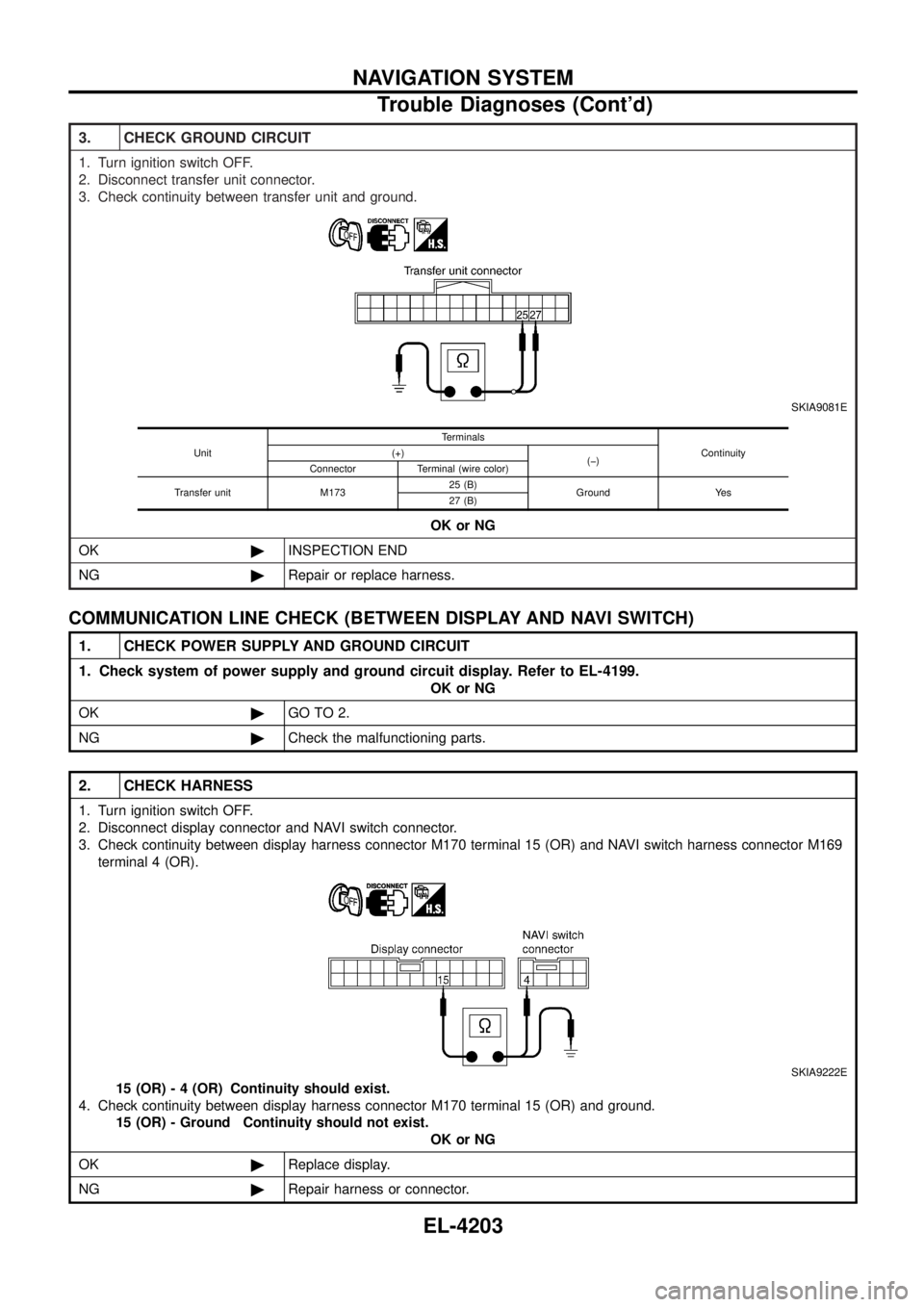
3. CHECK GROUND CIRCUIT
1. Turn ignition switch OFF.
2. Disconnect transfer unit connector.
3. Check continuity between transfer unit and ground.
SKIA9081E
OK or NG
OK ©INSPECTION END
NG ©Repair or replace harness.
Unit Terminals
Continuity
(+)
(þ)
Connector Terminal (wire color)
Transfer unit M173 25 (B)
Ground Yes
27 (B)
COMMUNICATION LINE CHECK (BETWEEN DISPLAY AND NAVI SWITCH)
1. CHECK POWER SUPPLY AND GROUND CIRCUIT
1. Check system of power supply and ground circuit display. Refer to EL-4199.
OK or NG
OK ©GO TO 2.
NG ©Check the malfunctioning parts.
2. CHECK HARNESS
1. Turn ignition switch OFF.
2. Disconnect display connector and NAVI switch connector.
3. Check continuity between display harness connector M170 terminal 15 (OR) and NAVI switch harness connector M169
terminal 4 (OR).
SKIA9222E
15 (OR) - 4 (OR) Continuity should exist.
4. Check continuity between display harness connector M170 terminal 15 (OR) and ground. 15 (OR) - Ground Continuity should not exist. OK or NG
OK ©Replace display.
NG ©Repair harness or connector.
NAVIGATION SYSTEM
Trouble Diagnoses (Cont'd)
EL-4203
Page 299 of 579
COMMUNICATION LINE CHECK (BETWEEN NAVI SWITCH AND TRANSFER UNIT)
1. CHECK POWER SUPPLY AND GROUND CIRCUIT
1. Check system of power supply and ground circuit NAVI switch. Refer to EL-4201
OK or NG
OK ©GO TO 2.
NG ©Check the malfunctioning parts.
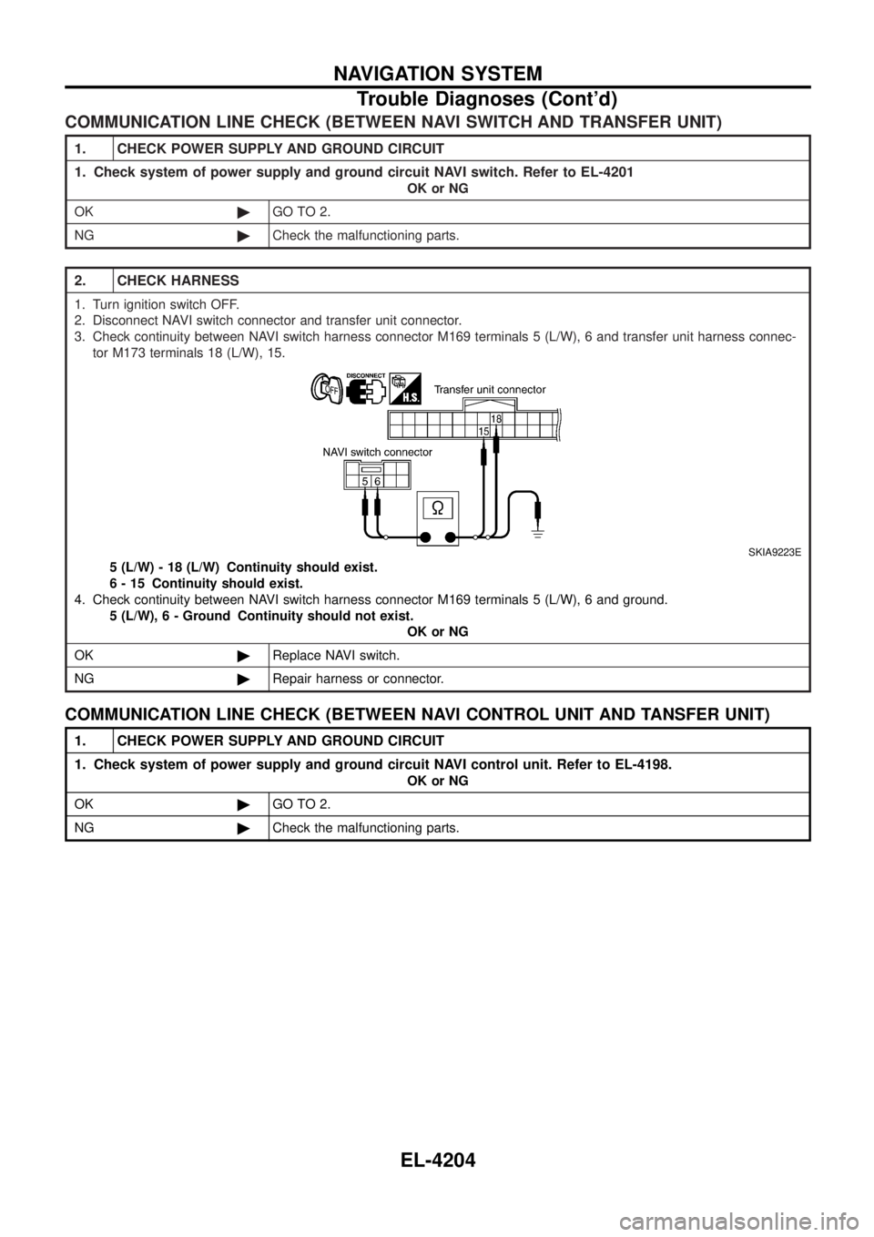
2. CHECK HARNESS
1. Turn ignition switch OFF.
2. Disconnect NAVI switch connector and transfer unit connector.
3. Check continuity between NAVI switch harness connector M169 terminals 5 (L/W), 6 and transfer unit harness connec-
tor M173 terminals 18 (L/W), 15.
SKIA9223E
5 (L/W) - 18 (L/W) Continuity should exist.
6 - 15 Continuity should exist.
4. Check continuity between NAVI switch harness connector M169 terminals 5 (L/W), 6 and ground. 5 (L/W) , 6 - Ground Continuity should not exist.
OK or NG
OK ©Replace NAVI switch.
NG ©Repair harness or connector.
COMMUNICATION LINE CHECK (BETWEEN NAVI CONTROL UNIT AND TANSFER UNIT)
1. CHECK POWER SUPPLY AND GROUND CIRCUIT
1. Check system of power supply and ground circuit NAVI control unit. Refer to EL-4198.
OK or NG
OK ©GO TO 2.
NG ©Check the malfunctioning parts.
NAVIGATION SYSTEM
Trouble Diagnoses (Cont'd)
EL-4204
Page 300 of 579
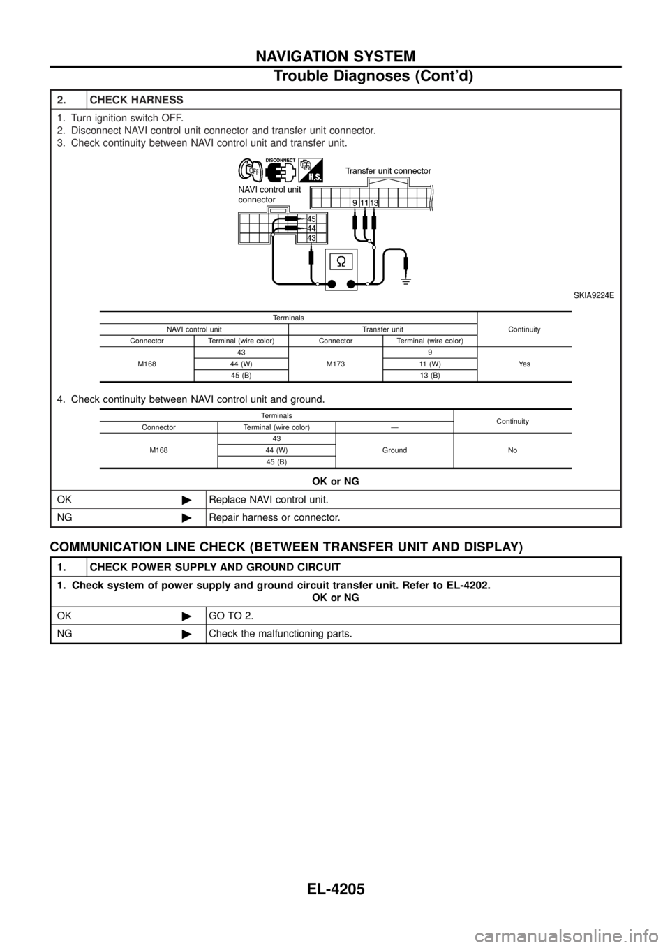
2. CHECK HARNESS
1. Turn ignition switch OFF.
2. Disconnect NAVI control unit connector and transfer unit connector.
3. Check continuity between NAVI control unit and transfer unit.
SKIA9224E
4. Check continuity between NAVI control unit and ground.OK or NG
OK ©Replace NAVI control unit.
NG ©Repair harness or connector.
Terminals
Continuity
NAVI control unit Transfer unit
Connector Terminal (wire color) Connector Terminal (wire color)
M168 43
M173 9
Ye s
44 (W) 11 (W)
45 (B) 13 (B)
Terminals Continuity
Connector Terminal (wire color) Ð
M168 43
Ground No
44 (W)
45 (B)
COMMUNICATION LINE CHECK (BETWEEN TRANSFER UNIT AND DISPLAY)
1. CHECK POWER SUPPLY AND GROUND CIRCUIT
1. Check system of power supply and ground circuit transfer unit. Refer to EL-4202.
OK or NG
OK ©GO TO 2.
NG ©Check the malfunctioning parts.
NAVIGATION SYSTEM
Trouble Diagnoses (Cont'd)
EL-4205
Page 481 of 579
Features (TB48 Engine Models)
CAN COMMUNICATION SYSTEM DESCRIPTION
CAN (Controller Area Network) is a serial communication line for real time application. It is an on-vehicle mul-
tiplex communication line with high data communication speed and excellent error detection ability. Many
electronic control units are equipped onto a vehicle, and each control unit shares information and links with
other control units during operation (not independent). In CAN communication, control units are connected with
2 communication lines (CAN H line, CAN L line) allowing a high rate of information transmission with less wir-
ing. Each control unit transmits/receives data but selectively reads required data only.
SYSTEM CONSTRUCTION
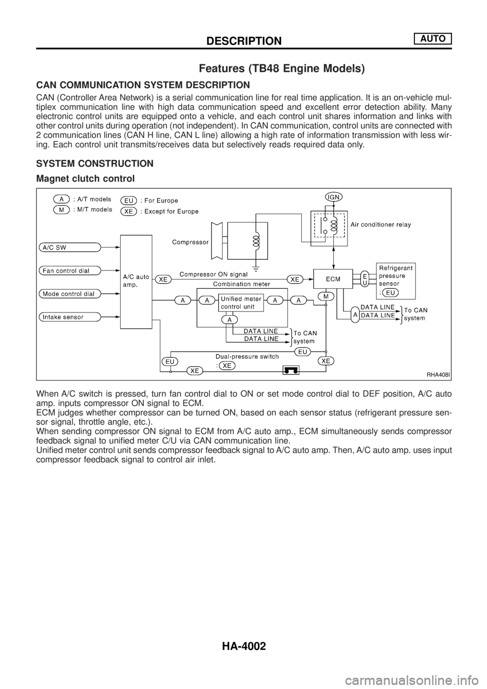
Magnet clutch control
When A/C switch is pressed, turn fan control dial to ON or set mode control dial to DEF position, A/C auto
amp. inputs compressor ON signal to ECM.
ECM judges whether compressor can be turned ON, based on each sensor status (refrigerant pressure sen-
sor signal, throttle angle, etc.).
When sending compressor ON signal to ECM from A/C auto amp., ECM simultaneously sends compressor
feedback signal to uni®ed meter C/U via CAN communication line.
Uni®ed meter control unit sends compressor feedback signal to A/C auto amp. Then, A/C auto amp. uses input
compressor feedback signal to control air inlet.
RHA408I
DESCRIPTIONAUTO
HA-4002