coolant temperature NISSAN PATROL 2004 Electronic Repair Manual
[x] Cancel search | Manufacturer: NISSAN, Model Year: 2004, Model line: PATROL, Model: NISSAN PATROL 2004Pages: 579, PDF Size: 26.61 MB
Page 74 of 579

MONITOR ITEM CONDITION SPECIFICATION
EGR VOL CON/V+Engine: After warming up
+Air conditioner switch: ªOFFº
+Shift lever: Neutral position
+No-loadAfter 1 minute of idling More than 10 steps
Revving engine from idle to 3,200 rpm 0 step
VNT S/V 1+Engine: After warming up
+Air conditioner switch: ªOFFº
+Shift lever: Neutral position
+No-loadIdle Approx. 56%
2,000 rpm Approx. 20%
BARO SEN+Ignition switch: ONAltitude
Approx.0m(0ft): Approx. 100.62
kPa (1.0062 bar, 1.026 kg/cm
2,
14.59 psi)
Approx. 1,000 m (3,281 ft): Approx.
88.95 kPa (0.8895 bar, 0.907
kg/cm
2, 12.90 psi)
Approx. 1,500 m (4,922 ft): Approx.
83.16 kPa (0.8316 bar, 0.848
kg/cm
2, 12.06 psi)
Approx. 2,000 m (6,562 ft): Approx.
78.36 kPa (0.7836 bar, 0.799
kg/cm
2, 11.36 psi)
SWRL CON S/V 1+Lift up the vehicle
+Engine: After warming up let it idle for
more than 1 second.
+Air conditioner switch: ªOFFº
+No-loadShift lever: Except ªPº and ªNeutralº posi-
tionsON
Shift lever: Neutral position OFF
EXH/GAS REG V*+Vehicle: Stopped
+Engine speed: Below 1,200 rpm
+Engine coolant temperature: Below 87ÉC (189ÉF)
+Heat up switch: ONON
Except aboveOFF
*: This item is applicable for cold area models. On other models, ªOFFº is always displayed.
TROUBLE DIAGNOSIS Ð GENERAL DESCRIPTIONZD30DDTi
CONSULT-II Reference Value in Data Monitor
Mode (Cont'd)
EC-4039
Page 76 of 579

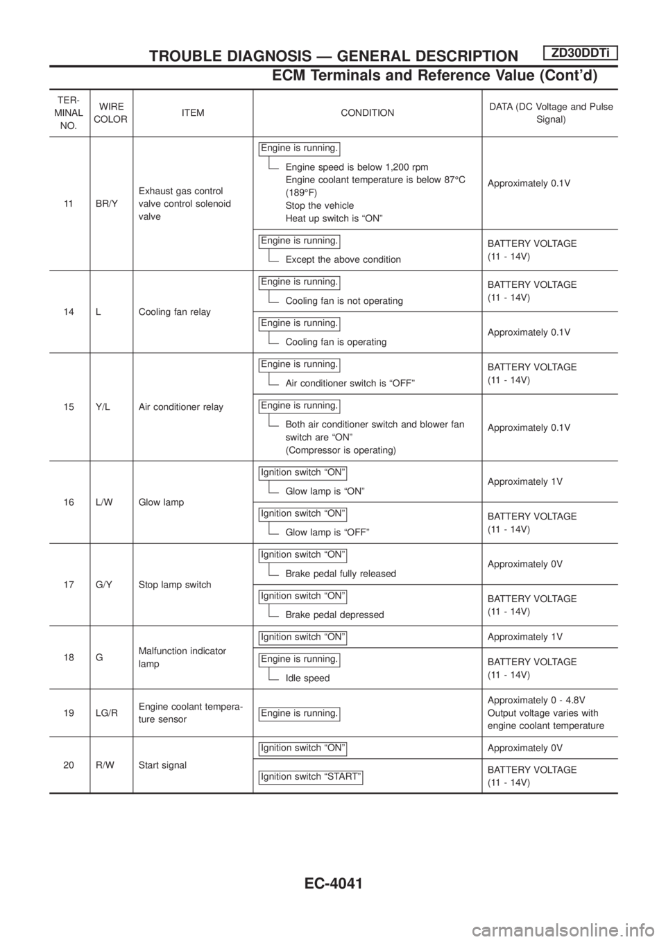
TER-
MINAL
NO.WIRE
COLORITEM CONDITIONDATA (DC Voltage and Pulse
Signal)
11 BR/YExhaust gas control
valve control solenoid
valveEngine is running.
Engine speed is below 1,200 rpm
Engine coolant temperature is below 87ÉC
(189ÉF)
Stop the vehicle
Heat up switch is ªONºApproximately 0.1V
Engine is running.
Except the above conditionBATTERY VOLTAGE
(11 - 14V)
14 L Cooling fan relayEngine is running.
Cooling fan is not operatingBATTERY VOLTAGE
(11 - 14V)
Engine is running.
Cooling fan is operatingApproximately 0.1V
15 Y/L Air conditioner relayEngine is running.
Air conditioner switch is ªOFFºBATTERY VOLTAGE
(11 - 14V)
Engine is running.
Both air conditioner switch and blower fan
switch are ªONº
(Compressor is operating)Approximately 0.1V
16 L/W Glow lampIgnition switch ªONº
Glow lamp is ªONºApproximately 1V
Ignition switch ªONº
Glow lamp is ªOFFºBATTERY VOLTAGE
(11 - 14V)
17 G/Y Stop lamp switchIgnition switch ªONº
Brake pedal fully releasedApproximately 0V
Ignition switch ªONº
Brake pedal depressedBATTERY VOLTAGE
(11 - 14V)
18 GMalfunction indicator
lampIgnition switch ªONº
Approximately 1V
Engine is running.
Idle speedBATTERY VOLTAGE
(11 - 14V)
19 LG/REngine coolant tempera-
ture sensorEngine is running.
Approximately 0 - 4.8V
Output voltage varies with
engine coolant temperature
20 R/W Start signalIgnition switch ªONº
Approximately 0V
Ignition switch ªSTARTº
BATTERY VOLTAGE
(11 - 14V)
TROUBLE DIAGNOSIS Ð GENERAL DESCRIPTIONZD30DDTi
ECM Terminals and Reference Value (Cont'd)
EC-4041
Page 526 of 579

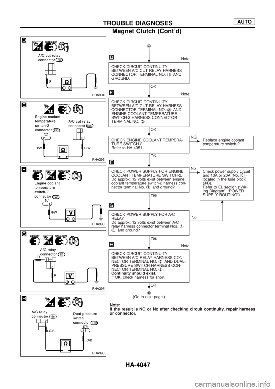
jA
Note
CHECK CIRCUIT CONTINUITY
BETWEEN A/C CUT RELAY HARNESS
CONNECTOR TERMINAL NO.j
1AND
GROUND.
OK
Note
CHECK CIRCUIT CONTINUITY
BETWEEN A/C CUT RELAY HARNESS
CONNECTOR TERMINAL NO.j
2AND
ENGINE COOLANT TEMPERATURE
SWITCH-2 HARNESS CONNECTOR
TERMINAL NO.j
2.
OK
CHECK ENGINE COOLANT TEMPERA-
TURE SWITCH-2.
Refer to HA-4051.
OK
cNG
Replace engine coolant
temperature switch-2.
CHECK POWER SUPPLY FOR ENGINE
COOLANT TEMPERATURE SWITCH-2.
Do approx. 12 volts exist between engine
coolant temperature switch-2 harness con-
nector terminal No.j
1and ground?
Ye s
cNo
Check power supply circuit
and 10A or 20A (No.
6)
located in the fuse block
(J/B).
Refer to EL section (ªWir-
ing Diagramº, ªPOWER
SUPPLY ROUTINGº).
CHECK POWER SUPPLY FOR A/C
RELAY.
Do approx. 12 volts exist between A/C
relay harness connector terminal Nos.j
1,
j6and ground?
Ye sNo
m
Note
CHECK CIRCUIT CONTINUITY
BETWEEN A/C RELAY HARNESS CON-
NECTOR TERMINAL NO.j
2AND DUAL-
PRESSURE SWITCH HARNESS CON-
NECTOR TERMINAL NO.j
2.
Continuity should exist.
If OK, check harness for short.
OK
j
B(Go to next page.)
Note:
If the result is NG or No after checking circuit continuity, repair harness
or connector.
RHA394I
RHA395I
RHA396I
RHA397I
RHA398I
.
.
.
.
.
.
.
TROUBLE DIAGNOSESAUTO
Magnet Clutch (Cont'd)
HA-4047
Page 530 of 579

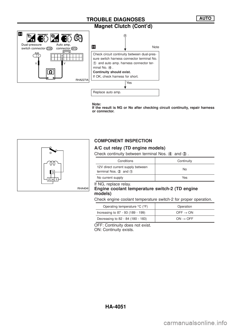
jB
Note
Check circuit continuity between dual-pres-
sure switch harness connector terminal No.
j
1and auto amp. harness connector ter-
minal No.j
4.
Continuity should exist.
If OK, check harness for short.
Ye s
Replace auto amp.
Note:
If the result is NG or No after checking circuit continuity, repair harness
or connector.
COMPONENT INSPECTION
A/C cut relay (TD engine models)
Check continuity between terminal Nos.j4andj3.
Conditions Continuity
12V direct current supply between
terminal Nos.j
2andj1No
No current supply Yes
If NG, replace relay.
Engine coolant temperature switch-2 (TD engine
models)
Check engine coolant temperature switch-2 for proper operation.
Operating temperature ÉC (ÉF) Operation
Increasing to 87 - 93 (189 - 199) OFF®ON
Decreasing to 82 - 84 (180 - 183) ON®OFF
OFF: Continuity does not exist.
ON: Continuity exists.
RHA227IA
RHA404I
.
.
TROUBLE DIAGNOSESAUTO
Magnet Clutch (Cont'd)
HA-4051