height NISSAN PATROL 2004 Electronic Repair Manual
[x] Cancel search | Manufacturer: NISSAN, Model Year: 2004, Model line: PATROL, Model: NISSAN PATROL 2004Pages: 579, PDF Size: 26.61 MB
Page 35 of 579
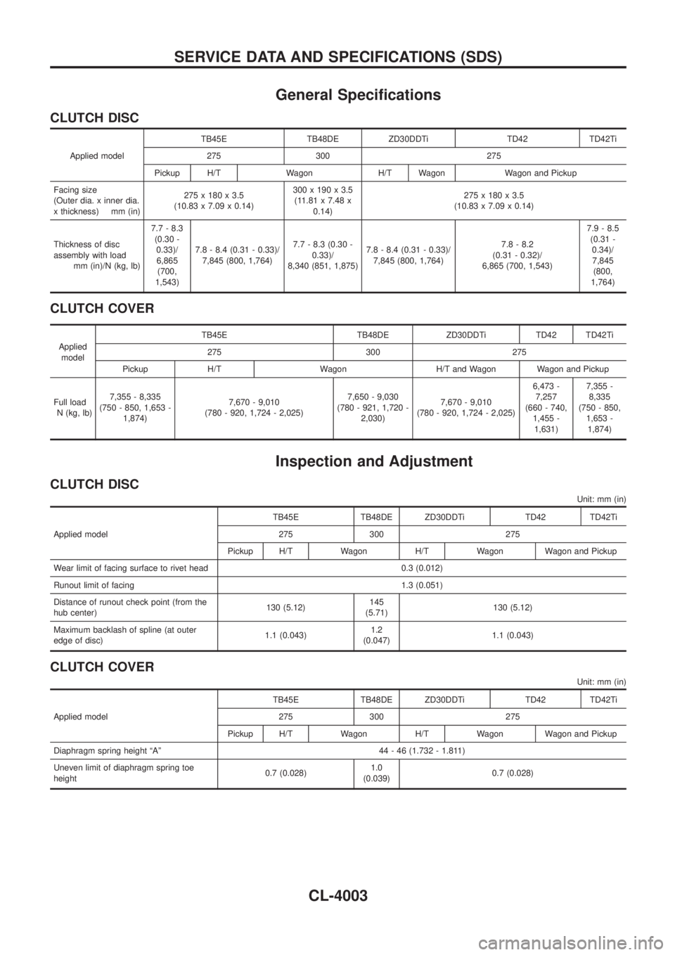
General Speci®cations
CLUTCH DISC
Applied modelTB45E TB48DE ZD30DDTi TD42 TD42Ti
275 300 275
Pickup H/T Wagon H/T Wagon Wagon and Pickup
Facing size
(Outer dia. x inner dia.
x thickness) mm (in)275 x 180 x 3.5
(10.83 x 7.09 x 0.14)300 x 190 x 3.5
(11.81 x 7.48 x
0.14)275 x 180 x 3.5
(10.83 x 7.09 x 0.14)
Thickness of disc
assembly with load
mm (in)/N (kg, lb)7.7 - 8.3
(0.30 -
0.33)/
6,865
(700,
1,543)7.8 - 8.4 (0.31 - 0.33)/
7,845 (800, 1,764)7.7 - 8.3 (0.30 -
0.33)/
8,340 (851, 1,875)7.8 - 8.4 (0.31 - 0.33)/
7,845 (800, 1,764)7.8 - 8.2
(0.31 - 0.32)/
6,865 (700, 1,543)7.9 - 8.5
(0.31 -
0.34)/
7,845
(800,
1,764)
CLUTCH COVER
Applied
modelTB45E TB48DE ZD30DDTi TD42 TD42Ti
275 300 275
Pickup H/T Wagon H/T and Wagon Wagon and Pickup
Full load
N (kg, lb)7,355 - 8,335
(750 - 850, 1,653 -
1,874)7,670 - 9,010
(780 - 920, 1,724 - 2,025)7,650 - 9,030
(780 - 921, 1,720 -
2,030)7,670 - 9,010
(780 - 920, 1,724 - 2,025)6,473 -
7,257
(660 - 740,
1,455 -
1,631)7,355 -
8,335
(750 - 850,
1,653 -
1,874)
Inspection and Adjustment
CLUTCH DISC
Unit: mm (in)
Applied modelTB45E TB48DE ZD30DDTi TD42 TD42Ti
275 300 275
Pickup H/T Wagon H/T Wagon Wagon and Pickup
Wear limit of facing surface to rivet head 0.3 (0.012)
Runout limit of facing 1.3 (0.051)
Distance of runout check point (from the
hub center)130 (5.12)145
(5.71)130 (5.12)
Maximum backlash of spline (at outer
edge of disc)1.1 (0.043)1.2
(0.047)1.1 (0.043)
CLUTCH COVER
Unit: mm (in)
Applied modelTB45E TB48DE ZD30DDTi TD42 TD42Ti
275 300 275
Pickup H/T Wagon H/T Wagon Wagon and Pickup
Diaphragm spring height ªAº 44 - 46 (1.732 - 1.811)
Uneven limit of diaphragm spring toe
height0.7 (0.028)1.0
(0.039)0.7 (0.028)
SERVICE DATA AND SPECIFICATIONS (SDS)
CL-4003
Page 259 of 579
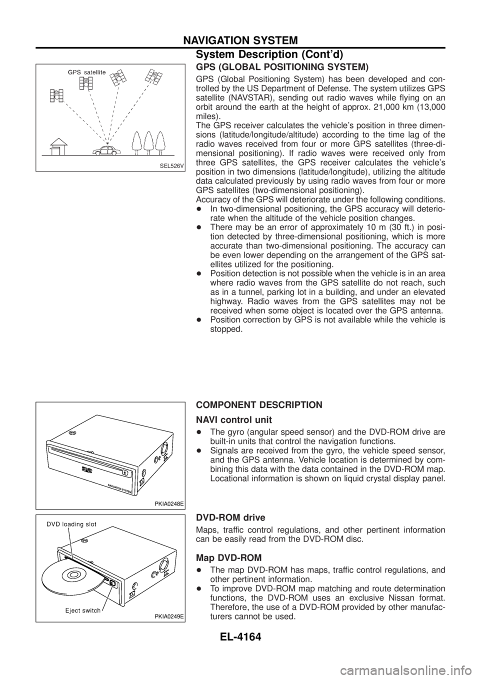
GPS (GLOBAL POSITIONING SYSTEM)
GPS (Global Positioning System) has been developed and con-
trolled by the US Department of Defense. The system utilizes GPS
satellite (NAVSTAR), sending out radio waves while ¯ying on an
orbit around the earth at the height of approx. 21,000 km (13,000
miles).
The GPS receiver calculates the vehicle's position in three dimen-
sions (latitude/longitude/altitude) according to the time lag of the
radio waves received from four or more GPS satellites (three-di-
mensional positioning). If radio waves were received only from
three GPS satellites, the GPS receiver calculates the vehicle's
position in two dimensions (latitude/longitude), utilizing the altitude
data calculated previously by using radio waves from four or more
GPS satellites (two-dimensional positioning).
Accuracy of the GPS will deteriorate under the following conditions.
+In two-dimensional positioning, the GPS accuracy will deterio-
rate when the altitude of the vehicle position changes.
+ There may be an error of approximately 10 m (30 ft.) in posi-
tion detected by three-dimensional positioning, which is more
accurate than two-dimensional positioning. The accuracy can
be even lower depending on the arrangement of the GPS sat-
ellites utilized for the positioning.
+ Position detection is not possible when the vehicle is in an area
where radio waves from the GPS satellite do not reach, such
as in a tunnel, parking lot in a building, and under an elevated
highway. Radio waves from the GPS satellites may not be
received when some object is located over the GPS antenna.
+ Position correction by GPS is not available while the vehicle is
stopped.
COMPONENT DESCRIPTION
NAVI control unit
+The gyro (angular speed sensor) and the DVD-ROM drive are
built-in units that control the navigation functions.
+ Signals are received from the gyro, the vehicle speed sensor,
and the GPS antenna. Vehicle location is determined by com-
bining this data with the data contained in the DVD-ROM map.
Locational information is shown on liquid crystal display panel.
DVD-ROM drive
Maps, traffic control regulations, and other pertinent information
can be easily read from the DVD-ROM disc.
Map DVD-ROM
+The map DVD-ROM has maps, traffic control regulations, and
other pertinent information.
+ To improve DVD-ROM map matching and route determination
functions, the DVD-ROM uses an exclusive Nissan format.
Therefore, the use of a DVD-ROM provided by other manufac-
turers cannot be used.
SEL526V
PKIA0248E
PKIA0249E
NAVIGATION SYSTEM
System Description (Cont'd)
EL-4164
Page 260 of 579
Gyro (Angular speed sensor)
+The oscillator gyro sensor is used to detect changes in vehicle
steering angle.
+ The gyro is built into the navigation (NAVI) control unit.
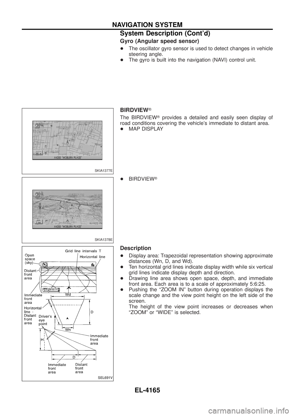
BIRDVIEW T
The BIRDVIEW Tprovides a detailed and easily seen display of
road conditions covering the vehicle's immediate to distant area.
+ MAP DISPLAY
+ BIRDVIEW T
Description
+Display area: Trapezoidal representation showing approximate
distances (Wn, D, and Wd).
+ Ten horizontal grid lines indicate display width while six vertical
grid lines indicate display depth and direction.
+ Drawing line area shows open space, depth, and immediate
front area. Each area is to a scale of approximately 5:6:25.
+ Pushing the ªZOOM INº button during operation displays the
scale change and the view point height on the left side of the
screen.
The height of the view point increases or decreases when
ªZOOMº or ªWIDEº is selected.
SKIA1377E
SKIA1378E
SEL691V
NAVIGATION SYSTEM
System Description (Cont'd)
EL-4165
Page 478 of 579
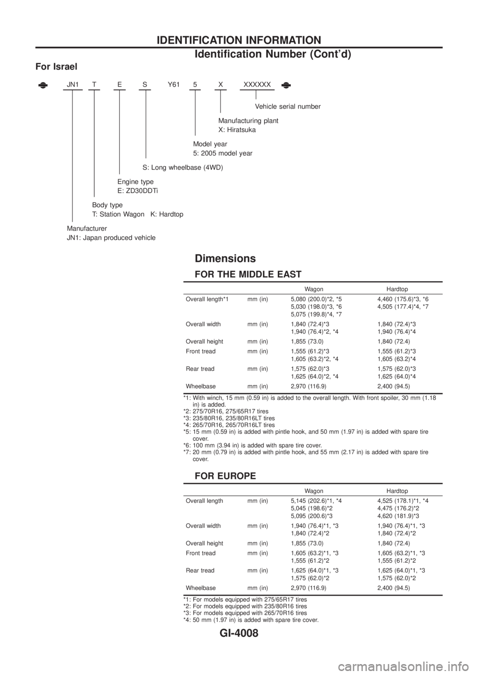
For Israel
JN1TESY61 5XXXXXXX
Vehicle serial number
Manufacturing plant
X: Hiratsuka
Model year
5: 2005 model year
S: Long wheelbase (4WD)
Engine type
E: ZD30DDTi
Body type
T: Station Wagon K: Hardtop
Manufacturer
JN1: Japan produced vehicle
Dimensions
FOR THE MIDDLE EAST
Wagon Hardtop
Overall length*1 mm (in) 5,080 (200.0)*2, *5
5,030 (198.0)*3, *6
5,075 (199.8)*4, *74,460 (175.6)*3, *6
4,505 (177.4)*4, *7
Overall width mm (in) 1,840 (72.4)*3
1,940 (76.4)*2, *41,840 (72.4)*3
1,940 (76.4)*4
Overall height mm (in) 1,855 (73.0) 1,840 (72.4)
Front tread mm (in) 1,555 (61.2)*3
1,605 (63.2)*2, *41,555 (61.2)*3
1,605 (63.2)*4
Rear tread mm (in) 1,575 (62.0)*3
1,625 (64.0)*2, *41,575 (62.0)*3
1,625 (64.0)*4
Wheelbase mm (in) 2,970 (116.9) 2,400 (94.5)
*1: With winch, 15 mm (0.59 in) is added to the overall length. With front spoiler, 30 mm (1.18
in) is added.
*2: 275/70R16, 275/65R17 tires
*3: 235/80R16, 235/80R16LT tires
*4: 265/70R16, 265/70R16LT tires
*5: 15 mm (0.59 in) is added with pintle hook, and 50 mm (1.97 in) is added with spare tire
cover.
*6: 100 mm (3.94 in) is added with spare tire cover.
*7: 20 mm (0.79 in) is added with pintle hook, and 55 mm (2.17 in) is added with spare tire
cover.
FOR EUROPE
Wagon Hardtop
Overall length mm (in) 5,145 (202.6)*1, *4
5,045 (198.6)*2
5,095 (200.6)*34,525 (178.1)*1, *4
4,475 (176.2)*2
4,620 (181.9)*3
Overall width mm (in) 1,940 (76.4)*1, *3
1,840 (72.4)*21,940 (76.4)*1, *3
1,840 (72.4)*2
Overall height mm (in) 1,855 (73.0) 1,840 (72.4)
Front tread mm (in) 1,605 (63.2)*1, *3
1,555 (61.2)*21,605 (63.2)*1, *3
1,555 (61.2)*2
Rear tread mm (in) 1,625 (64.0)*1, *3
1,575 (62.0)*21,625 (64.0)*1, *3
1,575 (62.0)*2
Wheelbase mm (in) 2,970 (116.9) 2,400 (94.5)
*1: For models equipped with 275/65R17 tires
*2: For models equipped with 235/80R16 tires
*3: For models equipped with 265/70R16 tires
*4: 50 mm (1.97 in) is added with spare tire cover.
IDENTIFICATION INFORMATION
Identi®cation Number (Cont'd)
GI-4008
Page 547 of 579
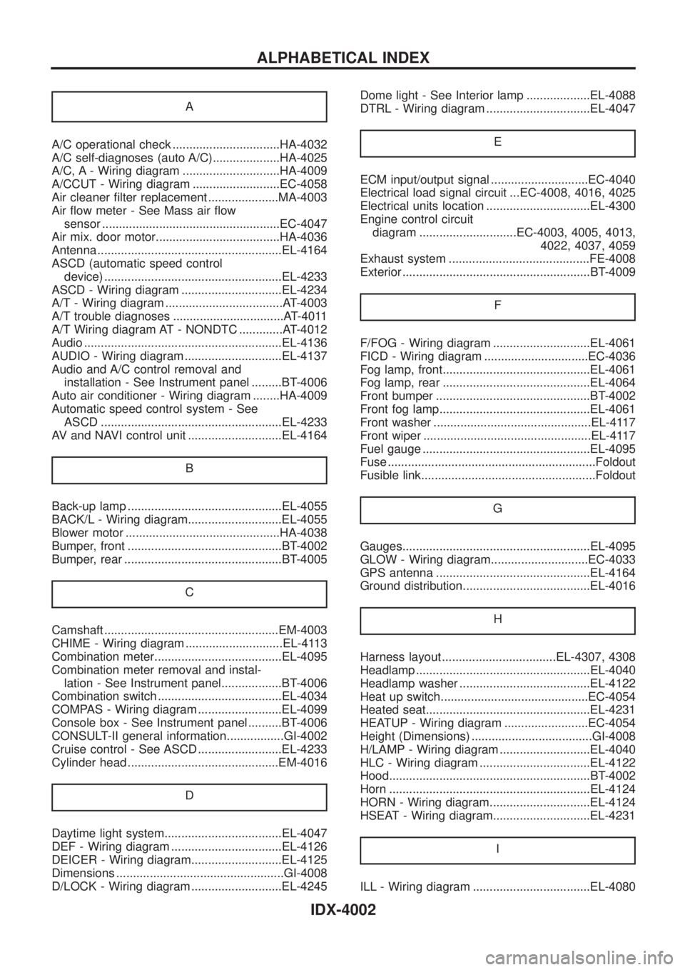
A
A/C operational check ................................HA-4032
A/C self-diagnoses (auto A/C)....................HA-4025
A/C, A - Wiring diagram .............................HA-4009
A/CCUT - Wiring diagram ..........................EC-4058
Air cleaner ®lter replacement .....................MA-4003
Air ¯ow meter - See Mass air ¯ow
sensor .....................................................EC-4047
Air mix. door motor.....................................HA-4036
Antenna .......................................................EL-4164
ASCD (automatic speed control
device) .....................................................EL-4233
ASCD - Wiring diagram ..............................EL-4234
A/T - Wiring diagram ...................................AT-4003
A/T trouble diagnoses .................................AT-4011
A/T Wiring diagram AT - NONDTC .............AT-4012
Audio ...........................................................EL-4136
AUDIO - Wiring diagram .............................EL-4137
Audio and A/C control removal and
installation - See Instrument panel .........BT-4006
Auto air conditioner - Wiring diagram ........HA-4009
Automatic speed control system - See
ASCD ......................................................EL-4233
AV and NAVI control unit ............................EL-4164
B
Back-up lamp ..............................................EL-4055
BACK/L - Wiring diagram............................EL-4055
Blower motor ..............................................HA-4038
Bumper, front ..............................................BT-4002
Bumper, rear ...............................................BT-4005
C
Camshaft ....................................................EM-4003
CHIME - Wiring diagram .............................EL-4113
Combination meter......................................EL-4095
Combination meter removal and instal-
lation - See Instrument panel..................BT-4006
Combination switch .....................................EL-4034
COMPAS - Wiring diagram .........................EL-4099
Console box - See Instrument panel ..........BT-4006
CONSULT-II general information.................GI-4002
Cruise control - See ASCD .........................EL-4233
Cylinder head .............................................EM-4016
D
Daytime light system...................................EL-4047
DEF - Wiring diagram .................................EL-4126
DEICER - Wiring diagram...........................EL-4125
Dimensions ..................................................GI-4008
D/LOCK - Wiring diagram ...........................EL-4245Dome light - See Interior lamp ...................EL-4088
DTRL - Wiring diagram ...............................EL-4047
E
ECM input/output signal .............................EC-4040
Electrical load signal circuit ...EC-4008, 4016, 4025
Electrical units location ...............................EL-4300
Engine control circuit
diagram .............................EC-4003, 4005, 4013,
4022, 4037, 4059
Exhaust system ..........................................FE-4008
Exterior ........................................................BT-4009
F
F/FOG - Wiring diagram .............................EL-4061
FICD - Wiring diagram ...............................EC-4036
Fog lamp, front............................................EL-4061
Fog lamp, rear ............................................EL-4064
Front bumper ..............................................BT-4002
Front fog lamp.............................................EL-4061
Front washer ...............................................EL-4117
Front wiper ..................................................EL-4117
Fuel gauge ..................................................EL-4095
Fuse ..............................................................Foldout
Fusible link....................................................Foldout
G
Gauges........................................................EL-4095
GLOW - Wiring diagram.............................EC-4033
GPS antenna ..............................................EL-4164
Ground distribution......................................EL-4016
H
Harness layout ..................................EL-4307, 4308
Headlamp ....................................................EL-4040
Headlamp washer .......................................EL-4122
Heat up switch............................................EC-4054
Heated seat.................................................EL-4231
HEATUP - Wiring diagram .........................EC-4054
Height (Dimensions) ....................................GI-4008
H/LAMP - Wiring diagram ...........................EL-4040
HLC - Wiring diagram .................................EL-4122
Hood............................................................BT-4002
Horn ............................................................EL-4124
HORN - Wiring diagram..............................EL-4124
HSEAT - Wiring diagram.............................EL-4231
I
ILL - Wiring diagram ...................................EL-4080
ALPHABETICAL INDEX
IDX-4002