Manual NISSAN PATROL 2006 Service Manual
[x] Cancel search | Manufacturer: NISSAN, Model Year: 2006, Model line: PATROL, Model: NISSAN PATROL 2006Pages: 1226, PDF Size: 37.18 MB
Page 1 of 1226
Edition: February 1998
Release: February 1998 (01)
Publication No.: SM8E-0Y61E0E
Reference No.: 7711346063GENERAL INFORMATIONGI
MAINTENANCEMA
ENGINE MECHANICALEM
ENGINE LUBRICATION &
COOLING SYSTEMSLC
ENGINE CONTROL SYSTEMEC
ACCELERATOR CONTROL,
FUEL & EXHAUST SYSTEMFE
CLUTCHCL
MANUAL TRANSMISSIONMT
AUTOMATIC TRANSMISSIONAT
TRANSFERTF
PROPELLER SHAFT &
DIFFERENTIAL CARRIERPD
FRONT AXLE & FRONT SUSPENSIONFA
REAR AXLE & REAR SUSPENSIONRA
BRAKE SYSTEMBR
STEERING SYSTEMST
RESTRAINT SYSTEMRS
BODY & TRIMBT
HEATER & AIR CONDITIONERHA
ELECTRICAL SYSTEMEL
ALPHABETICAL INDEXIDX
PATROL GR
MODEL Y61 SERIES
NISSAN EUROPE S.A.S.
1998 NISSAN EUROPE S.A.S.
Produced in The Netherlands
Not to be reproduced in whole or in part
without the prior written permission of
Nissan Europe S.A.S., Paris, France.
QUICK REFERENCE INDEX
Page 2 of 1226
FOREWORD
This manual contains maintenance and repair procedures for NISSAN
PATROL GR,modelY61 series.
In order to assure your safety and the efficient functioning of the vehicle,
this manual should be read thoroughly. It is especially important that the
PRECAUTIONS in the GI section be completely understood before starting
any repair task.
All information in this manual is based on the latest product information
at the time of publication. The right is reserved to make changes in speci-
®cations and methods at any time without notice.
IMPORTANT SAFETY NOTICE
The proper performance of service is essential for both the safety of the
technician and the efficient functioning of the vehicle.
The service methods in this Service Manual are described in such a man-
ner that the service may be performed safely and accurately.
Service varies with the procedures used, the skills of the technician and the
tools and parts available. Accordingly, anyone using service procedures,
tools or parts which are not speci®cally recommended by NISSAN must
®rst completely satisfy himself that neither his safety nor the vehicle's
safety will be jeopardized by the service method selected.
NISSAN EUROPE S.A.S.
Service Engineering SectionParis, France
Page 5 of 1226
Supplemental Restraint System (SRS) ``AIR
BAG'' and ``SEAT BELT PRE-TENSIONER''
The Supplemental Restraint System such as ``AIR BAG'' and ``SEAT BELT PRE-TENSIONER'' used along with
a seat belt, helps to reduce the risk or severity of injury to the driver and front passenger in a frontal collision.
The SRS system composition which is available to NISSAN MODEL Y61 is as follows (The composition var-
ies according to the destination.):
Driver air bag module (located in the center of the steering wheel), front passenger air bag module (located
on the instrument panel on passenger side), seat belt pre-tensioner, a diagnosis sensor unit, warning lamp,
wiring harness and spiral cable.
Information necessary to service the system safely is included in theRS sectionof this Service Manual.
WARNING:
+ To avoid rendering the SRS inoperative, which could increase the risk of personal injury or death
in the event of a collision which would result in air bag in¯ation, all maintenance must be performed
by an authorized NISSAN dealer.
+ Improper maintenance, including incorrect removal and installation of the SRS, can lead to per-
sonal injury caused by unintentional activation of the system. For removal of Spiral Cable and Air
Bag Module, see the RS section.
+ Do not use electrical test equipment on any circuit related to the SRS unless instructed to in this
Service Manual. Spiral Cable and wiring harnesses covered with yellow insulation either just before
the harness connectors or for the complete harness are related to the SRS.
Precautions for Brake System
+Use brake ¯uid ``DOT 3''.
+ Never reuse drained brake ¯uid.
+ Be careful not to splash brake ¯uid on painted areas; it
may cause paint damage. If brake ¯uid is splashed on
painted areas, wash it away with water immediately.
+ To clean master cylinder parts, disc brake caliper parts or
wheel cylinder parts, use clean brake ¯uid.
+ Never use mineral oils such as gasoline or kerosene. They
will ruin rubber parts of hydraulic system.
+ Use ¯are nut wrench when removing and installing brake
tubes.
+ Always torque brake lines when installing.
WARNING:
Clean brakes with a vacuum dust collector to minimize risk of
health hazard from powder caused by friction.
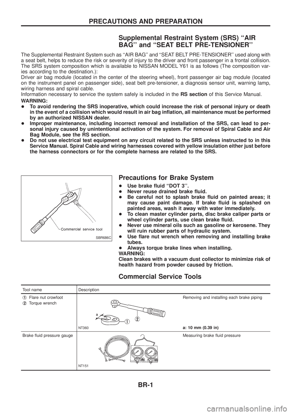
Commercial Service Tools
Tool name Description
j
1Flare nut crowfoot
j
2Torque wrench
NT360
Removing and installing each brake piping
a: 10 mm (0.39 in)
Brake ¯uid pressure gauge
NT151
Measuring brake ¯uid pressure
SBR686C
PRECAUTIONS AND PREPARATION
BR-1
Page 79 of 1226
Service Notice
+When removing or installing various parts, place a cloth or padding onto the vehicle body to prevent
scratches.
+Handle trim, molding, instruments, grille, etc. carefully during removing or installing. Be careful not to soil
or damage them.
+Apply sealing compound where necessary when installing parts.
+When applying sealing compound, be careful that the sealing compound does not protrude from parts.
+When replacing any metal parts (for example body outer panel, members, etc.), be sure to take rust pre-
vention measures.
Supplemental Restraint System (SRS) ``AIR
BAG'' and ``SEAT BELT PRE-TENSIONER''
The Supplemental Restraint System such as ``AIR BAG'' and ``SEAT BELT PRE-TENSIONER'' used along with
a seat belt, helps to reduce the risk or severity of injury to the driver and front passenger in a frontal collision.
The SRS system composition which is available to NISSAN MODEL Y61 is as follows (The composition var-
ies according to the destination.):
Driver air bag module (located in the center of the steering wheel), front passenger air bag module (located
on the instrument panel on passenger side), seat belt pre-tensioner, a diagnosis sensor unit, warning lamp,
wiring harness and spiral cable.
Information necessary to service the system safely is included in theRS sectionof this Service Manual.
WARNING:
+To avoid rendering the SRS inoperative, which could increase the risk of personal injury or death
in the event of a collision which would result in air bag in¯ation, all maintenance must be performed
by an authorized NISSAN dealer.
+Improper maintenance, including incorrect removal and installation of the SRS, can lead to per-
sonal injury caused by unintentional activation of the system. For removal of Spiral Cable and Air
Bag Module, see the RS section.
+Do not use electrical test equipment on any circuit related to the SRS unless instructed to in this
Service Manual. Spiral cable and wiring harnesses covered with yellow insulation either just before
the harness connectors or for the complete harness are related to the SRS.
PRECAUTIONS
BT-1
Page 110 of 1226
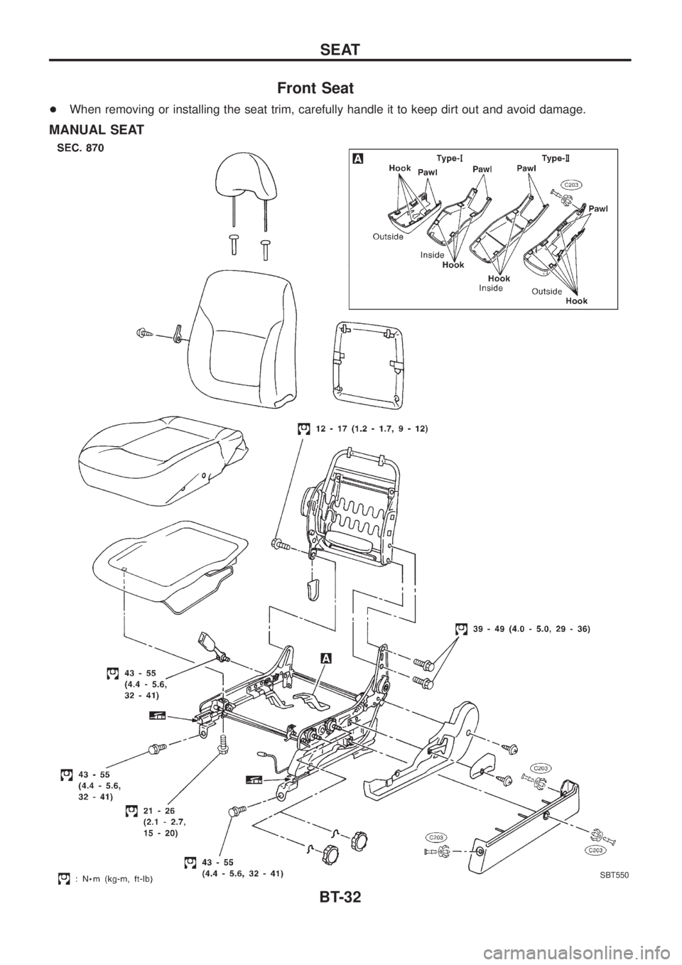
Front Seat
+When removing or installing the seat trim, carefully handle it to keep dirt out and avoid damage.
MANUAL SEAT
SBT550
SEAT
BT-32
Page 155 of 1226
Supplemental Restraint System (SRS) ``AIR
BAG'' and ``SEAT BELT PRE-TENSIONER''
The Supplemental Restraint System such as ``AIR BAG'' and ``SEAT BELT PRE-TENSIONER'' used along with
a seat belt, helps to reduce the risk or severity of injury to the driver and front passenger in a frontal collision.
The SRS system composition which is available to NISSAN MODEL Y61 is as follows (The composition var-
ies according to the destination.):
Driver air bag module (located in the center of the steering wheel), front passenger air bag module (located
on the instrument panel on passenger side), seat belt pre-tensioner, a diagnosis sensor unit, warning lamp,
wiring harness and spiral cable.
Information necessary to service the system safely is included in theRS sectionof this Service Manual.
WARNING:
+To avoid rendering the SRS inoperative, which could increase the risk of personal injury or death
in the event of a collision which would result in air bag in¯ation, all maintenance must be performed
by an authorized NISSAN dealer.
+Improper maintenance, including incorrect removal and installation of the SRS, can lead to per-
sonal injury caused by unintentional activation of the system. For removal of Spiral Cable and Air
Bag Module, see the RS section.
+Do not use electrical test equipment on any circuit related to the SRS unless instructed to in this
Service Manual. Spiral cable and wiring harnesses covered with yellow insulation either just before
the harness connectors or for the complete harness are related to the SRS.
PRECAUTIONS AND PREPARATION
EC-4
Page 185 of 1226
DIAGNOSTIC TEST MODE IÐBULB CHECK
In this mode, the MALFUNCTION INDICATOR LAMP on the instrument panel should stay ON. If it remains
OFF, check the bulb. Refer to EL section (``WARNING LAMPS AND CHIME'') or see EC-188.
DIAGNOSTIC TEST MODE IÐMALFUNCTION WARNING
MALFUNCTION
INDICATOR LAMPCondition
ONWhen the malfunction is detected or the ECM's CPU is malfunctioning. (Refer to ``MIL Illumination'' of the
``DIAGNOSTIC TROUBLE CODE INDEX'', EC-1.)
OFF No malfunction.
+These Diagnostic Trouble Code Numbers are clari®ed in Diagnostic Test Mode II (SELF-DIAGNOSTIC
RESULTS).
DIAGNOSTIC TEST MODE IIÐSELF-DIAGNOSTIC RESULTS
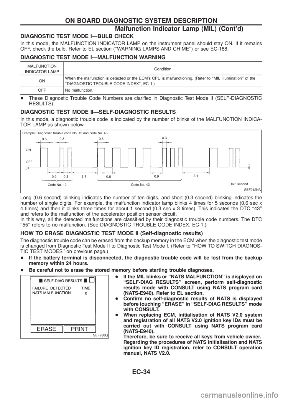
In this mode, a diagnostic trouble code is indicated by the number of blinks of the MALFUNCTION INDICA-
TOR LAMP as shown below.
Long (0.6 second) blinking indicates the number of ten digits, and short (0.3 second) blinking indicates the
number of single digits. For example, the malfunction indicator lamp blinks 4 times for 5 seconds (0.6 sec x
4 times) and then it blinks three times for about 1 second (0.3 sec x 3 times). This indicates the DTC ``43''
and refers to the malfunction of the accelerator position sensor circuit.
In this way, all the detected malfunctions are classi®ed by their diagnostic trouble code numbers. The DTC
``55'' refers to no malfunction. (See DIAGNOSTIC TROUBLE CODE INDEX, EC-1.)
HOW TO ERASE DIAGNOSTIC TEST MODE II (Self-diagnostic results)
The diagnostic trouble code can be erased from the backup memory in the ECM when the diagnostic test mode
is changed from Diagnostic Test Mode II to Diagnostic Test Mode I. (Refer to ``HOW TO SWITCH DIAGNOS-
TIC TEST MODES'' on previous page.)
+If the battery terminal is disconnected, the diagnostic trouble code will be lost from the backup
memory within 24 hours.
+Be careful not to erase the stored memory before starting trouble diagnoses.
+If the MIL blinks or ``NATS MALFUNCTION'' is displayed on
``SELF-DIAG RESULTS'' screen, perform self-diagnostic
results mode with CONSULT using NATS program card
(NATS-E940). Refer to EL section.
+Con®rm no self-diagnostic results of NATS is displayed
before touching ``ERASE'' in ``SELF-DIAG RESULTS'' mode
with CONSULT.
+When replacing ECM, initialisation of NATS V2.0 system
and registration of all NATS V2.0 ignition key IDs must be
carried out with CONSULT using NATS program card
(NATS-E940).
Therefore, be sure to receive all keys from vehicle owner.
Regarding the procedures of NATS initialisation and NATS
ignition key ID registration, refer to CONSULT operation
manual, NATS V2.0.
SEF212NA
SEF288Q
ON BOARD DIAGNOSTIC SYSTEM DESCRIPTION
Malfunction Indicator Lamp (MIL) (Cont'd)
EC-34
Page 187 of 1226
CONSULT
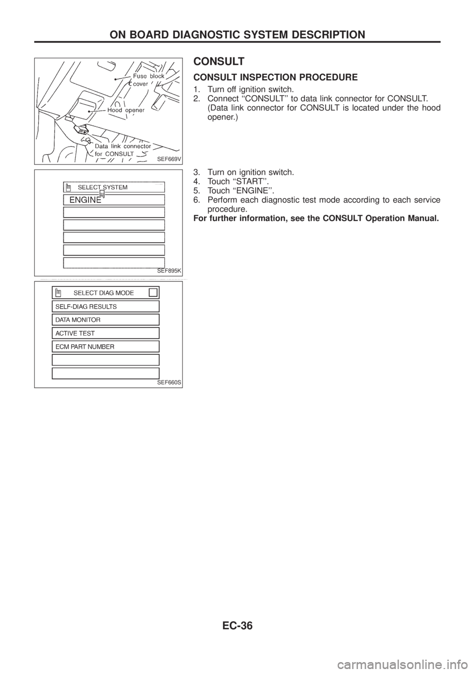
CONSULT INSPECTION PROCEDURE
1. Turn off ignition switch.
2. Connect ``CONSULT'' to data link connector for CONSULT.
(Data link connector for CONSULT is located under the hood
opener.)
3. Turn on ignition switch.
4. Touch ``START''.
5. Touch ``ENGINE''.
6. Perform each diagnostic test mode according to each service
procedure.
For further information, see the CONSULT Operation Manual.
SEF669V
SEF895K
SEF660S
ON BOARD DIAGNOSTIC SYSTEM DESCRIPTION
EC-36
Page 192 of 1226
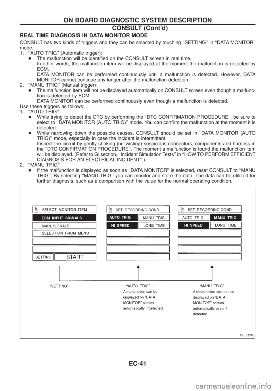
REAL TIME DIAGNOSIS IN DATA MONITOR MODE
CONSULT has two kinds of triggers and they can be selected by touching ``SETTING'' in ``DATA MONITOR''
mode.
1. ``AUTO TRIG'' (Automatic trigger):
+The malfunction will be identi®ed on the CONSULT screen in real time.
In other words, the malfunction item will be displayed at the moment the malfunction is detected by
ECM.
DATA MONITOR can be performed continuously until a malfunction is detected. However, DATA
MONITOR cannot continue any longer after the malfunction detection.
2. ``MANU TRIG'' (Manual trigger):
+The malfunction item will not be displayed automatically on CONSULT screen even though a malfunc-
tion is detected by ECM.
DATA MONITOR can be performed continuously even though a malfunction is detected.
Use these triggers as follows:
1. ``AUTO TRIG''
+While trying to detect the DTC by performing the ``DTC CONFIRMATION PROCEDURE'', be sure to
select to ``DATA MONITOR (AUTO TRIG)'' mode. You can con®rm the malfunction at the moment it is
detected.
+While narrowing down the possible causes, CONSULT should be set in ``DATA MONITOR (AUTO
TRIG)'' mode, especially in case the incident is intermittent.
Inspect the circuit by gently shaking (or twisting) suspicious connectors, components and harness in
the ``DTC CONFIRMATION PROCEDURE''. The moment a malfunction is found the malfunction item
will be displayed. (Refer to GI section, ``Incident Simulation Tests'' in ``HOW TO PERFORM EFFICIENT
DIAGNOSIS FOR AN ELECTRICAL INCIDENT''.)
2. ``MANU TRIG''
+If the malfunction is displayed as soon as ``DATA MONITOR'' is selected, reset CONSULT to ``MANU
TRIG''. By selecting ``MANU TRIG'' you can monitor and store the data. The data can be utilized for
further diagnosis, such as a comparison with the value for the normal operating condition.
SEF529Q
ON BOARD DIAGNOSTIC SYSTEM DESCRIPTION
CONSULT (Cont'd)
EC-41
Page 294 of 1226
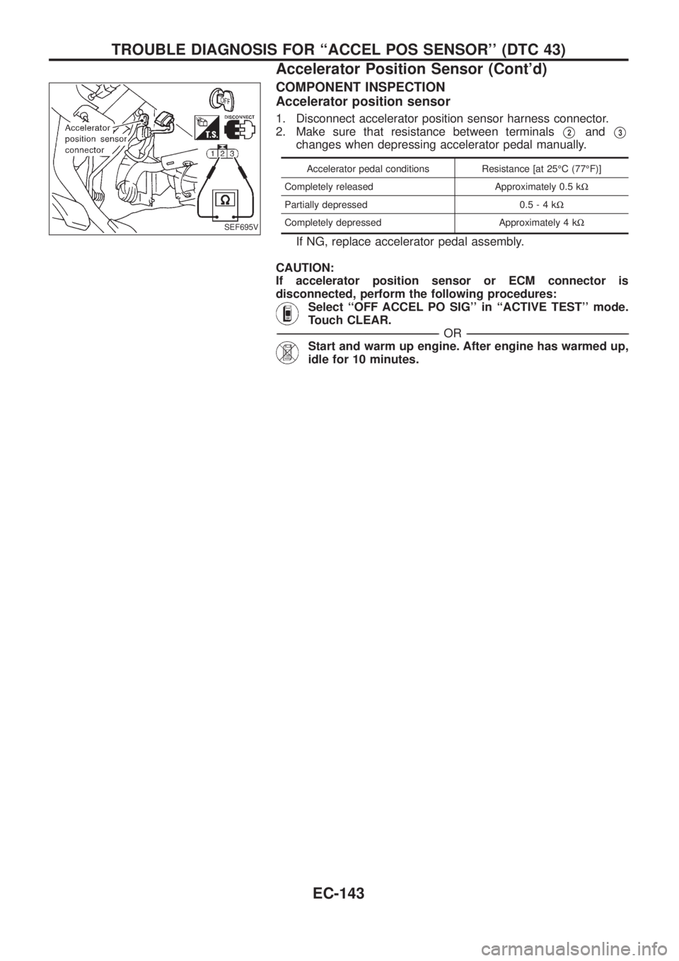
COMPONENT INSPECTION
Accelerator position sensor
1. Disconnect accelerator position sensor harness connector.
2. Make sure that resistance between terminals
V2andV3
changes when depressing accelerator pedal manually.
Accelerator pedal conditions Resistance [at 25ÉC (77ÉF)]
Completely released Approximately 0.5 kW
Partially depressed 0.5-4kW
Completely depressed Approximately 4 kW
If NG, replace accelerator pedal assembly.
CAUTION:
If accelerator position sensor or ECM connector is
disconnected, perform the following procedures:
Select ``OFF ACCEL PO SIG'' in ``ACTIVE TEST'' mode.
Touch CLEAR.
-------------------------------------------------------------------------------------------------------------------------------------------------------------------------------------------------------------------------------------------------------OR-------------------------------------------------------------------------------------------------------------------------------------------------------------------------------------------------------------------------------------------------------
Start and warm up engine. After engine has warmed up,
idle for 10 minutes.
SEF695V
TROUBLE DIAGNOSIS FOR ``ACCEL POS SENSOR'' (DTC 43)
Accelerator Position Sensor (Cont'd)
EC-143