engine overheat NISSAN PATROL 2006 Service Manual
[x] Cancel search | Manufacturer: NISSAN, Model Year: 2006, Model line: PATROL, Model: NISSAN PATROL 2006Pages: 1226, PDF Size: 37.18 MB
Page 151 of 1226
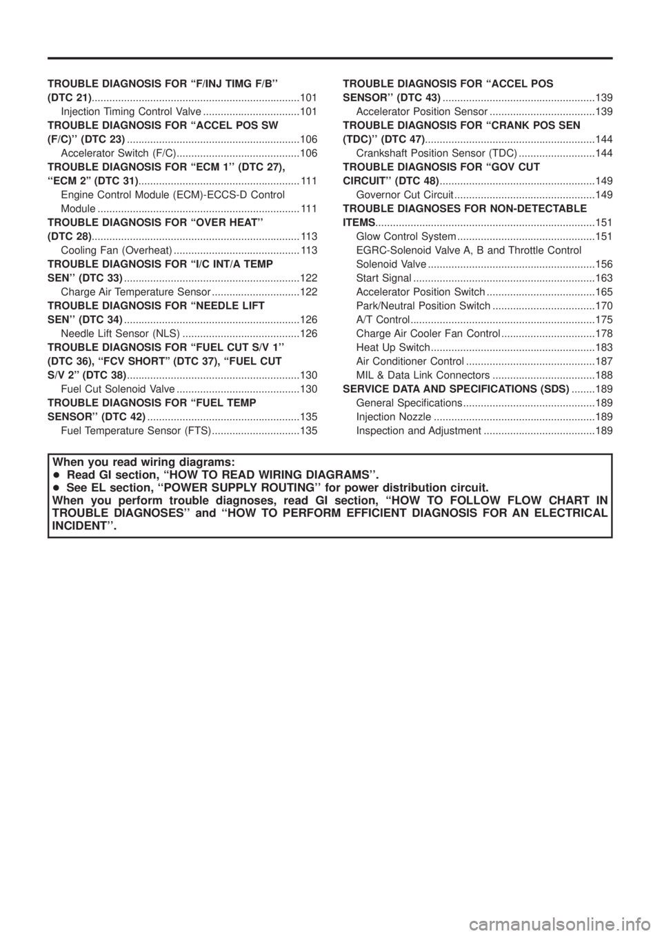
TROUBLEDIAGNOSISFOR``F/INJTIMGF/B''
(DTC21).......................................................................101
InjectionTimingControlValve.................................101
TROUBLEDIAGNOSISFOR``ACCELPOSSW
(F/C)''(DTC23) ...........................................................106
AcceleratorSwitch(F/C)..........................................106
TROUBLEDIAGNOSISFOR``ECM1''(DTC27),
``ECM2''(DTC31) .......................................................111
EngineControlModule(ECM)-ECCS-DControl
Module.....................................................................111
TROUBLEDIAGNOSISFOR``OVERHEAT''
(DTC28) .......................................................................113
CoolingFan(Overheat)...........................................113
TROUBLEDIAGNOSISFOR``I/CINT/ATEMP
SEN''(DTC33) ............................................................122
ChargeAirTemperatureSensor..............................122
TROUBLEDIAGNOSISFOR``NEEDLELIFT
SEN''(DTC34) ............................................................126
NeedleLiftSensor(NLS)........................................126
TROUBLE DIAGNOSIS FOR ``FUEL CUT S/V 1''
(DTC 36), ``FCV SHORT'' (DTC 37), ``FUEL CUT
S/V2''(DTC38) ...........................................................130
FuelCutSolenoidValve..........................................130
TROUBLE DIAGNOSIS FOR ``FUEL TEMP
SENSOR''(DTC42) ....................................................135
FuelTemperatureSensor(FTS)..............................135 TROUBLE DIAGNOSIS FOR ``ACCEL POS
SENSOR''(DTC43)
....................................................139
AcceleratorPositionSensor....................................139
TROUBLE DIAGNOSIS FOR ``CRANK POS SEN
(TDC)''(DTC47) ..........................................................144
CrankshaftPositionSensor(TDC)..........................144
TROUBLEDIAGNOSISFOR``GOVCUT
CIRCUIT''(DTC48) .....................................................149
GovernorCutCircuit................................................149
TROUBLEDIAGNOSESFORNON-DETECTABLE
ITEMS ........................................................................\
...151
GlowControlSystem...............................................151
EGRC-SolenoidValveA,BandThrottleControl
SolenoidValve.........................................................156
StartSignal..............................................................163
AcceleratorPositionSwitch.....................................165
Park/NeutralPositionSwitch...................................170
A/TControl...............................................................175
ChargeAirCoolerFanControl................................178
HeatUpSwitch........................................................183
AirConditionerControl............................................187
MIL&DataLinkConnectors...................................188
SERVICEDATAANDSPECIFICATIONS(SDS) ........189
GeneralSpeci®cations.............................................189
InjectionNozzle.......................................................189
InspectionandAdjustment......................................189
When you read wiring diagrams:
+ Read GI section, ``HOW TO READ WIRING DIAGRAMS''.
+ See EL section, ``POWER SUPPLY ROUTING'' for power distribution circuit.
When you perform trouble diagnoses, read GI section, ``HOW TO FOLLOW FLOW CHART IN
TROUBLE DIAGNOSES'' and ``HOW TO PERFORM EFFICIENT DIAGNOSIS FOR AN ELECTRICAL
INCIDENT''.
Page 199 of 1226
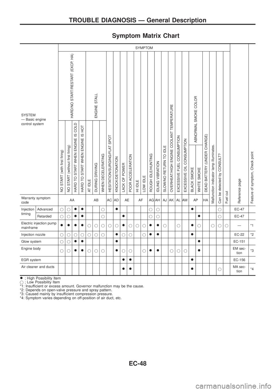
Symptom Matrix Chart
SYSTEM
Ð Basic engine
control systemSYMPTOM
Reference page
Feature of symptom, Check pointHARD/NO START/RESTART (EXCP. HA)
ENGINE STALL
HESITATION/SURGING/FLAT SPOT
KNOCK/DETONATION
LACK OF POWER
POOR ACCELERATION
HI IDLE
LOW IDLE
ROUGH IDLE/HUNTING
IDLING VIBRATION
SLOW/NO RETURN TO IDLE
OVERHEAT/HIGH ENGINE COOLANT TEMPERATURE
EXCESSIVE FUEL CONSUMPTION
EXCESSIVE OIL CONSUMPTION
ABNORMAL SMOKE COLOR
DEAD BATTERY (UNDER CHARGE)
Malfunction indicator lamp illuminates.
Can be detected by CONSULT?
Fuel cutNO START (with ®rst ®ring)
NO START (without ®rst ®ring)
HARD TO START WHEN ENGINE IS COLD
HARD TO START WHEN ENGINE IS HOT
AT IDLE
DURING DRIVING
WHEN DECELERATING
BLACK SMOKE
WHITE SMOKEWarranty symptom
codeAA AB AC AD AE AF AG AH AJ AK AL AM AP HA
Injection
timingAdvancedjj
++j+jj+jEC-47
Retardedjj
++j+jj+jEC-47
Electric injection pump
mainframe
++++jjjjj+jjj++jj+j jjjÐ*1
Injection nozzlejjjjjjj
+jj j++ +EC-22 *2
Glow systemjj
++ + +EC-151
Engine body
jj
++jjj+jj j++jjj+EM sec-
tion*3
EGR system
++ +EC-156
Air cleaner and ducts
++ +jMA sec-
tion*4
+; High Possibility Item
j; Low Possibility Item
*1: Insufficient or excess amount. Governor malfunction may be the cause.
*2: Depends on open-valve pressure and spray pattern.
*3: Caused mainly by insufficient compression pressure.
*4: Symptom varies depending on off-position of air duct, etc.
TROUBLE DIAGNOSIS Ð General Description
EC-48
Page 200 of 1226
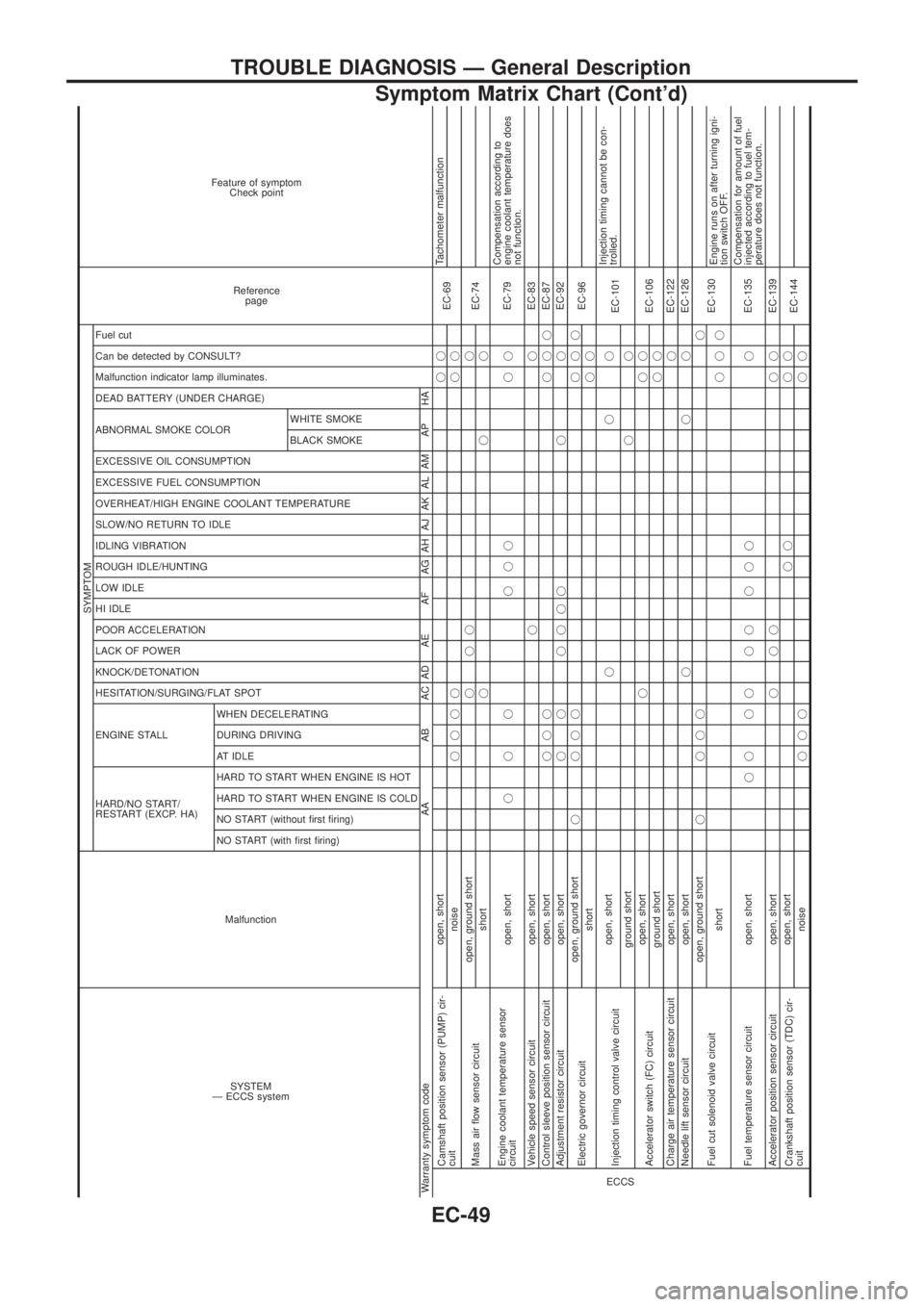
SYSTEM
Ð ECCS systemMalfunction
SYMPTOM
Reference
page Feature of symptom
Check point
HARD/NO START/
RESTART (EXCP. HA) ENGINE STALL HESITATION/SURGING/FLAT SPOT KNOCK/DETONATION
LACK OF POWER
POOR ACCELERATION
HI IDLE
LOW IDLE
ROUGH IDLE/HUNTING
IDLING VIBRATION
SLOW/NO RETURN TO IDLE
OVERHEAT/HIGH ENGINE COOLANT TEMPERATURE
EXCESSIVE FUEL CONSUMPTION
EXCESSIVE OIL CONSUMPTION ABNORMAL SMOKE COLOR
DEAD BATTERY (UNDER CHARGE) Malfunction indicator lamp illuminates.
Can be detected by CONSULT?
Fuel cut
NO START (with ®rst ®ring) NO START (without ®rst ®ring)
HARD TO START WHEN ENGINE IS COLD
HARD TO START WHEN ENGINE IS HOT
AT IDLE
DURING DRIVING
WHEN DECELERATINGBLACK SMOKE WHITE SMOKE
Warranty symptom code AA AB AC AD AE AF AG AH AJ AK AL AM AP HAECCS
Camshaft position sensor (PUMP) cir-
cuitopen, shortjj
EC-69Tachometer malfunction
noisejjjj jj
Mass air ¯ow sensor circuitopen, ground shortjjj j
EC-74
shortjjj
Engine coolant temperature sensor
circuitopen, shortjjj jjj jjEC-79Compensation according to
engine coolant temperature does
not function.
Vehicle speed sensor circuit open, shortjjEC-83
Control sleeve position sensor circuit open, shortjjjjjjEC-87
Adjustment resistor circuit open, shortj j jjjj j jEC-92
Electric governor circuitopen, ground shortj jjjjjj
EC-96
shortjj
Injection timing control valve circuitopen, shortjjj
EC-101Injection timing cannot be con-
trolled.
ground shortjj
Accelerator switch (FC) circuitopen, shortjjj
EC-106
ground shortjj
Charge air temperature sensor circuit open, shortjEC-122
Needle lift sensor circuit open, shortjjjEC-126
Fuel cut solenoid valve circuitopen, ground shortj jjjj
EC-130
shortjjjEngine runs on after turning igni-
tion switch OFF.
Fuel temperature sensor circuit open, shortjj jj jj j jj jEC-135Compensation for amount of fuel
injected according to fuel tem-
perature does not function.
Accelerator position sensor circuit open, shortjjj jjEC-139
Crankshaft position sensor (TDC) cir-
cuitopen, shortjj jj
EC-144
noisejjjjj
TROUBLE DIAGNOSIS Ð General Description
Symptom Matrix Chart (Cont'd)
EC-49
Page 201 of 1226
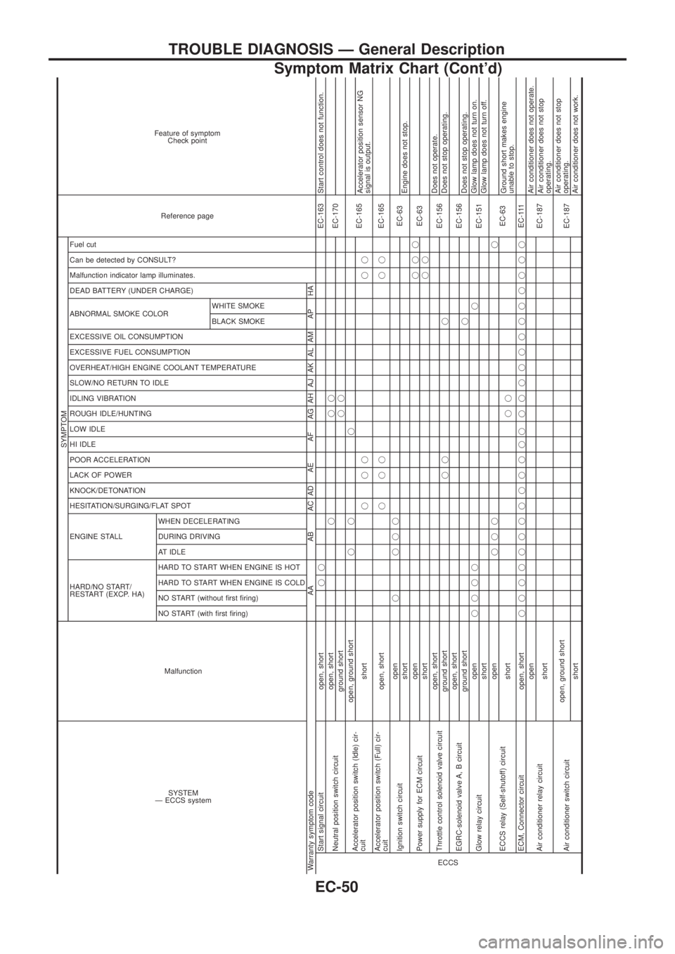
SYSTEM
Ð ECCS systemMalfunction
SYMPTOM
Reference page Feature of symptom
Check point
HARD/NO START/
RESTART (EXCP. HA) ENGINE STALL HESITATION/SURGING/FLAT SPOT KNOCK/DETONATION
LACK OF POWER
POOR ACCELERATION
HI IDLE
LOW IDLE
ROUGH IDLE/HUNTING
IDLING VIBRATION
SLOW/NO RETURN TO IDLE
OVERHEAT/HIGH ENGINE COOLANT TEMPERATURE
EXCESSIVE FUEL CONSUMPTION
EXCESSIVE OIL CONSUMPTION ABNORMAL SMOKE COLOR
DEAD BATTERY (UNDER CHARGE) Malfunction indicator lamp illuminates.
Can be detected by CONSULT?
Fuel cut
NO START (with ®rst ®ring) NO START (without ®rst ®ring)
HARD TO START WHEN ENGINE IS COLD
HARD TO START WHEN ENGINE IS HOT
AT IDLE
DURING DRIVING
WHEN DECELERATINGBLACK SMOKE WHITE SMOKE
Warranty symptom code AA AB AC AD AE AF AG AH AJ AK AL AM AP HAECCS
Start signal circuit open, shortjjEC-163 Start control does not function.
Neutral position switch circuitopen, shortjjj
EC-170
ground shortjj
Accelerator position switch (Idle) cir-
cuitopen, ground shortjj j
EC-165
shortjjj jjAccelerator position sensor NG
signal is output.
Accelerator position switch (Full) cir-
cuitopen, shortjjj jjEC-165
Ignition switch circuitopenj jjj
EC-63
shortEngine does not stop.
Power supply for ECM circuitopenjjj
EC-63
shortjj
Throttle control solenoid valve circuitopen, short
EC-156Does not operate.
ground shortjj jDoes not stop operating.
EGRC-solenoid valve A, B circuitopen, short
EC-156
ground shortjDoes not stop operating.
Glow relay circuitopenjjjjj
EC-151Glow lamp does not turn on.
shortGlow lamp does not turn off.
ECCS relay (Self-shutoff) circuitopenjjjj
EC-63
shortjjGround short makes engine
unable to stop.
ECM, Connector circuit open, shortjjjjjjjjjjjjj jjjjjjjjjjjjEC-111
Air conditioner relay circuitopen
EC-187Air conditioner does not operate.
shortAir conditioner does not stop
operating.
Air conditioner switch circuitopen, ground short
EC-187Air conditioner does not stop
operating.
shortAir conditioner does not work.
TROUBLE DIAGNOSIS Ð General Description
Symptom Matrix Chart (Cont'd)
EC-50
Page 264 of 1226

Cooling Fan (Overheat)
SYSTEM DESCRIPTION
Vehicle speed sensorcVehicle speed
ECM
(ECCS-D
control
mod-
ule)
cCooling fan
relayEngine coolant temperature sensorcEngine coolant temperature
Air conditioner switch
cAir conditioner ``ON'' signal
The ECM controls the cooling fan corresponding to the vehicle speed, engine coolant temperature, air condi-
tioner system pressure and air conditioner ON signal. The control system has 2-step control [ON/OFF].
Operation
CONSULT REFERENCE VALUE IN DATA MONITOR MODE
Remarks: Speci®cation data are reference values.
MONITOR ITEM CONDITION SPECIFICATION
AIR COND SIG+Engine: After warming up, idle
the engineAir conditioner switch: OFF OFF
Air conditioner switch: ON
(Compressor operates.)ON
COOLING FAN+When cooling fan is stopped. OFF
+When cooling fan operates. ON
ECM TERMINALS AND REFERENCE VALUE
Remarks: Speci®cation data are reference values and are measured between each terminal andV43(ECCS
ground) with a voltmeter.
TER-
MINAL
NO.WIRE
COLORITEM CONDITIONDATA
(DC Voltage and Pulse
Signal)
14 L Cooling fan relayEngine is running.
Cooling fan is not operating.BATTERY VOLTAGE
(11 - 14V)
Engine is running.
Cooling fan is operating.0-1V
SEF757V
TROUBLE DIAGNOSIS FOR ``OVER HEAT'' (DTC 28)
EC-113
Page 265 of 1226
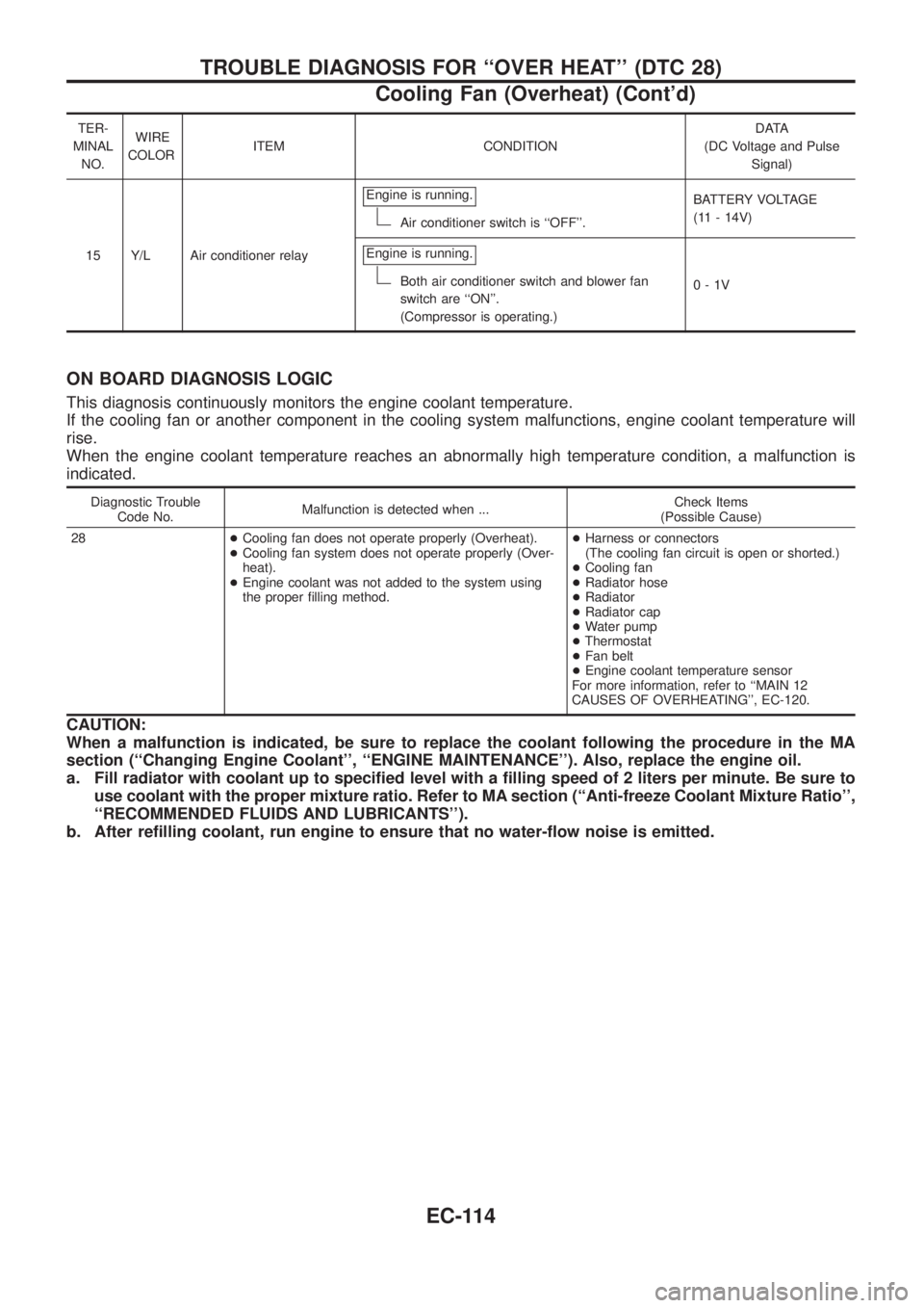
TER-
MINAL
NO.WIRE
COLORITEM CONDITIONDATA
(DC Voltage and Pulse
Signal)
15 Y/L Air conditioner relayEngine is running.
Air conditioner switch is ``OFF''.BATTERY VOLTAGE
(11 - 14V)
Engine is running.
Both air conditioner switch and blower fan
switch are ``ON''.
(Compressor is operating.)0-1V
ON BOARD DIAGNOSIS LOGIC
This diagnosis continuously monitors the engine coolant temperature.
If the cooling fan or another component in the cooling system malfunctions, engine coolant temperature will
rise.
When the engine coolant temperature reaches an abnormally high temperature condition, a malfunction is
indicated.
Diagnostic Trouble
Code No.Malfunction is detected when ...Check Items
(Possible Cause)
28+Cooling fan does not operate properly (Overheat).
+Cooling fan system does not operate properly (Over-
heat).
+Engine coolant was not added to the system using
the proper ®lling method.+Harness or connectors
(The cooling fan circuit is open or shorted.)
+Cooling fan
+Radiator hose
+Radiator
+Radiator cap
+Water pump
+Thermostat
+Fan belt
+Engine coolant temperature sensor
For more information, refer to ``MAIN 12
CAUSES OF OVERHEATING'', EC-120.
CAUTION:
When a malfunction is indicated, be sure to replace the coolant following the procedure in the MA
section (``Changing Engine Coolant'', ``ENGINE MAINTENANCE''). Also, replace the engine oil.
a. Fill radiator with coolant up to speci®ed level with a ®lling speed of 2 liters per minute. Be sure to
use coolant with the proper mixture ratio. Refer to MA section (``Anti-freeze Coolant Mixture Ratio'',
``RECOMMENDED FLUIDS AND LUBRICANTS'').
b. After re®lling coolant, run engine to ensure that no water-¯ow noise is emitted.
TROUBLE DIAGNOSIS FOR ``OVER HEAT'' (DTC 28)
Cooling Fan (Overheat) (Cont'd)
EC-114
Page 266 of 1226
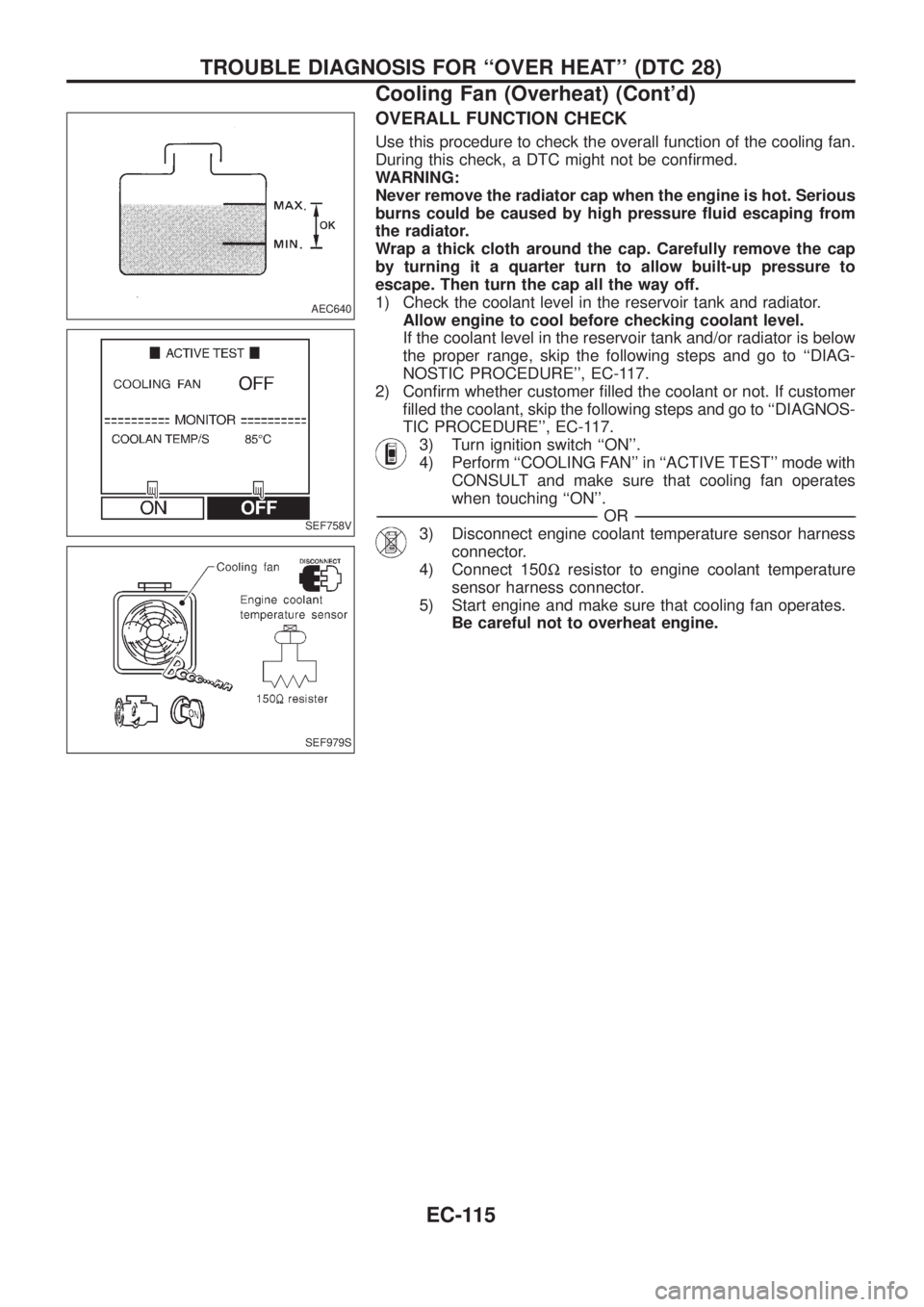
OVERALL FUNCTION CHECK
Use this procedure to check the overall function of the cooling fan.
During this check, a DTC might not be con®rmed.
WARNING:
Never remove the radiator cap when the engine is hot. Serious
burns could be caused by high pressure ¯uid escaping from
the radiator.
Wrap a thick cloth around the cap. Carefully remove the cap
by turning it a quarter turn to allow built-up pressure to
escape. Then turn the cap all the way off.
1) Check the coolant level in the reservoir tank and radiator.
Allow engine to cool before checking coolant level.
If the coolant level in the reservoir tank and/or radiator is below
the proper range, skip the following steps and go to ``DIAG-
NOSTIC PROCEDURE'', EC-117.
2) Con®rm whether customer ®lled the coolant or not. If customer
®lled the coolant, skip the following steps and go to ``DIAGNOS-
TIC PROCEDURE'', EC-117.
3) Turn ignition switch ``ON''.
4) Perform ``COOLING FAN'' in ``ACTIVE TEST'' mode with
CONSULT and make sure that cooling fan operates
when touching ``ON''.
-------------------------------------------------------------------------------------------------------------------------------------------------------------------------------------------------------------------------------------------------------OR-------------------------------------------------------------------------------------------------------------------------------------------------------------------------------------------------------------------------------------------------------
3) Disconnect engine coolant temperature sensor harness
connector.
4) Connect 150Wresistor to engine coolant temperature
sensor harness connector.
5) Start engine and make sure that cooling fan operates.
Be careful not to overheat engine.
AEC640
SEF758V
SEF979S
TROUBLE DIAGNOSIS FOR ``OVER HEAT'' (DTC 28)
Cooling Fan (Overheat) (Cont'd)
EC-115
Page 268 of 1226
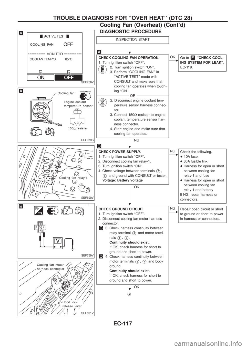
DIAGNOSTIC PROCEDURE
INSPECTION START
CHECK COOLING FAN OPERATION.
1. Turn ignition switch ``OFF''.
2. Turn ignition switch ``ON''.
3. Perform ``COOLING FAN'' in
``ACTIVE TEST'' mode with
CONSULT and make sure that
cooling fan operates when touch-
ing ``ON''.
--------------------------------------------------------------------------------------------------------------------------------------OR--------------------------------------------------------------------------------------------------------------------------------------
2. Disconnect engine coolant tem-
perature sensor harness connec-
tor.
3. Connect 150Wresistor to engine
coolant temperature sensor har-
ness connector.
4. Start engine and make sure that
cooling fan operates.
NG
cOK
Go to``CHECK COOL-
ING SYSTEM FOR LEAK'',
EC-119.
CHECK POWER SUPPLY.
1. Turn ignition switch ``OFF''.
2. Disconnect cooling fan relay-1.
3. Turn ignition switch ``ON''.
4. Check voltage between terminals
V2,
V5and ground with CONSULT or tester.
Voltage: Battery voltage
OK
cNG
Check the following.
+10A fuse
+30A fusible link
+Harness for open or short
between cooling fan
relay-1 and fuse
+Harness for open or short
between cooling fan
relay-1 and battery
If NG, repair harness or
connectors.
CHECK GROUND CIRCUIT.
1. Turn ignition switch ``OFF''.
2. Disconnect cooling fan motor harness
connector.
3. Check harness continuity between
relay terminal
V3and motor termi-
nals
V1,V3.
Continuity should exist.
If OK, check harness for short to
ground and short to power.
4. Check harness continuity between
motor terminals
V2,V4and body
ground.
Continuity should exist.
If OK, check harness for short to
ground and short to power.
OK
cNG
Repair open circuit or short
to ground or short to power
in harness or connectors.
jA
SEF758V
SEF979S
SEF690V
SEF759V
SEF691V
.
.
.
.
TROUBLE DIAGNOSIS FOR ``OVER HEAT'' (DTC 28)
Cooling Fan (Overheat) (Cont'd)
EC-117
Page 270 of 1226
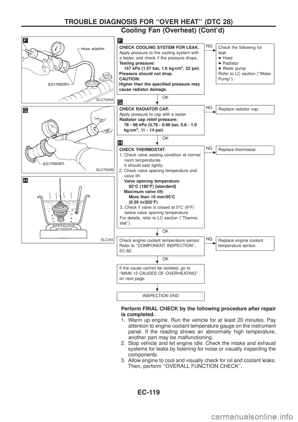
CHECK COOLING SYSTEM FOR LEAK.
Apply pressure to the cooling system with
a tester, and check if the pressure drops.
Testing pressure:
157 kPa (1.57 bar, 1.6 kg/cm
2, 23 psi)
Pressure should not drop.
CAUTION:
Higher than the speci®ed pressure may
cause radiator damage.
OK
cNG
Check the following for
leak.
+Hose
+Radiator
+Water pump
Refer to LC section (``Water
Pump'').
CHECK RADIATOR CAP.
Apply pressure to cap with a tester.
Radiator cap relief pressure:
78 - 98 kPa (0.78 - 0.98 bar, 0.8 - 1.0
kg/cm
2, 11 - 14 psi)
OK
cNG
Replace radiator cap.
CHECK THERMOSTAT.
1. Check valve seating condition at normal
room temperatures.
It should seat tightly.
2. Check valve opening temperature and
valve lift.
Valve opening temperature:
82ÉC (180ÉF) [standard]
Maximum valve lift:
More than 10 mm/95ÉC
(0.39 in/203ÉF)
3. Check if valve is closed at 5ÉC (9ÉF)
below valve opening temperature.
For details, refer to LC section (``Thermo-
stat'').
OK
cNG
Replace thermostat.
Check engine coolant temperature sensor.
Refer to ``COMPONENT INSPECTION'',
EC-82.
OK
cNG
Replace engine coolant
temperature sensor.
If the cause cannot be isolated, go to
``MAIN 12 CAUSES OF OVERHEATING''
on next page.
INSPECTION END
Perform FINAL CHECK by the following procedure after repair
is completed.
1. Warm up engine. Run the vehicle for at least 20 minutes. Pay
attention to engine coolant temperature gauge on the instrument
panel. If the reading shows an abnormally high temperature,
another part may be malfunctioning.
2. Stop vehicle and let engine idle. Check the intake and exhaust
systems for leaks by listening for noise or visually inspecting the
components.
3. Allow engine to cool and visually check for oil and coolant leaks.
Then, perform ``OVERALL FUNCTION CHECK''.
SLC754AA
SLC755AB
SLC343
.
.
.
.
.
TROUBLE DIAGNOSIS FOR ``OVER HEAT'' (DTC 28)
Cooling Fan (Overheat) (Cont'd)
EC-119
Page 271 of 1226
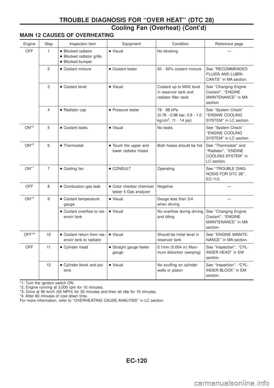
MAIN 12 CAUSES OF OVERHEATING
Engine Step Inspection item Equipment Condition Reference page
OFF 1+Blocked radiator
+Blocked radiator grille
+Blocked bumper+Visual No blocking Ð
2+Coolant mixture+Coolant tester 50 - 50% coolant mixture See ``RECOMMENDED
FLUIDS AND LUBRI-
CANTS'' in MA section.
3+Coolant level+Visual Coolant up to MAX level
in reservoir tank and
radiator ®ller neckSee ``Changing Engine
Coolant'', ``ENGINE
MAINTENANCE'' in MA
section.
4+Radiator cap+Pressure tester 78 - 98 kPa
(0.78 - 0.98 bar, 0.8 - 1.0
kg/cm
2, 11 - 14 psi)See ``System Check''
``ENGINE COOLING
SYSTEM'' in LC section.
ON*
25+Coolant leaks+Visual No leaks See ``System Check''
``ENGINE COOLING
SYSTEM'' in LC section.
ON*
26+Thermostat+Touch the upper and
lower radiator hosesBoth hoses should be hot See ``Thermostat'' and
``Radiator'', ``ENGINE
COOLING SYSTEM'' in
LC section.
ON*
17+Cooling fan+CONSULT Operating See ``TROUBLE DIAG-
NOSIS FOR DTC 28'',
EC-113.
OFF 8+Combustion gas leak+Color checker chemical
tester 4 Gas analyzerNegative Ð
ON*
39+Coolant temperature
gauge+Visual Gauge less than 3/4
when drivingÐ
+Coolant over¯ow to res-
ervoir tank+Visual No over¯ow during driving
and idlingSee ``Changing Engine
Coolant'', ``ENGINE
MAINTENANCE'' in MA
section.
OFF*
410+Coolant return from res-
ervoir tank to radiator+Visual Should be initial level in
reservoir tankSee ``ENGINE MAINTE-
NANCE'' in MA section.
OFF 11+Cylinder head+Straight gauge feeler
gauge0.1mm (0.004 in) Maxi-
mum distortion (warping)See ``Inspection'', ``CYL-
INDER HEAD'' in EM
section.
12+Cylinder block and pis-
tons+Visual No scuffing on cylinder
walls or pistonSee ``Inspection'', ``CYL-
INDER BLOCK'' in EM
section.
*1: Turn the ignition switch ON.
*2: Engine running at 3,000 rpm for 10 minutes.
*3: Drive at 90 km/h (55 MPH) for 30 minutes and then let idle for 10 minutes.
*4: After 60 minutes of cool down time.
For more information, refer to ``OVERHEATING CAUSE ANALYSIS'' in LC section.
TROUBLE DIAGNOSIS FOR ``OVER HEAT'' (DTC 28)
Cooling Fan (Overheat) (Cont'd)
EC-120