power steering NISSAN PATROL 2006 Service Manual
[x] Cancel search | Manufacturer: NISSAN, Model Year: 2006, Model line: PATROL, Model: NISSAN PATROL 2006Pages: 1226, PDF Size: 37.18 MB
Page 342 of 1226
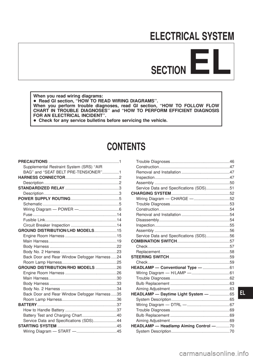
ELECTRICAL SYSTEM
SECTION
EL
When you read wiring diagrams:
+Read GI section, ``HOW TO READ WIRING DIAGRAMS''.
When you perform trouble diagnoses, read GI section, ``HOW TO FOLLOW FLOW
CHART IN TROUBLE DIAGNOSES'' and ``HOW TO PERFORM EFFICIENT DIAGNOSIS
FOR AN ELECTRICAL INCIDENT''.
+Check for any service bulletins before servicing the vehicle.
CONTENTS
PRECAUTIONS...............................................................1
Supplemental Restraint System (SRS) ``AIR
BAG'' and ``SEAT BELT PRE-TENSIONER''...............1
HARNESS CONNECTOR................................................2
Description ...................................................................2
STANDARDIZED RELAY................................................3
Description ...................................................................3
POWER SUPPLY ROUTING...........................................5
Schematic ....................................................................5
Wiring Diagram Ð POWER Ð....................................6
Fuse ...........................................................................14
Fusible Link................................................................14
Circuit Breaker Inspection .........................................14
GROUND DISTRIBUTION/LHD MODELS....................15
Engine Room Harness ..............................................15
Main Harness.............................................................19
Body Harness ............................................................22
Body No. 2 Harness ..................................................23
Back Door and Rear Window Defogger Harness .....24
Room Lamp Harness.................................................25
GROUND DISTRIBUTION/RHD MODELS...................26
Engine Room Harness ..............................................26
Main Harness.............................................................30
Body Harness ............................................................33
Body No. 2 Harness ..................................................34
Back Door and Rear Window Defogger Harness .....35
Room Lamp Harness.................................................36
BATTERY.......................................................................37
How to Handle Battery ..............................................37
Battery Test and Charging Chart ...............................40
Service Data and Speci®cations (SDS).....................44
STARTING SYSTEM.....................................................45
Wiring Diagram Ð START Ð ....................................45Trouble Diagnoses.....................................................46
Construction ...............................................................47
Removal and Installation ...........................................47
Inspection...................................................................47
Assembly ...................................................................50
Service Data and Speci®cations (SDS).....................51
CHARGING SYSTEM....................................................52
Wiring Diagram Ð CHARGE Ð ................................52
Trouble Diagnoses.....................................................53
Construction ...............................................................54
Removal and Installation ...........................................54
Disassembly...............................................................54
Inspection...................................................................55
Assembly ...................................................................56
Service Data and Speci®cations (SDS).....................56
COMBINATION SWITCH...............................................57
Check .........................................................................57
Replacement ..............................................................58
STEERING SWITCH......................................................59
Check .........................................................................59
HEADLAMP Ð Conventional Type Ð........................61
Wiring Diagram Ð H/LAMP Ð ..................................61
Trouble Diagnoses.....................................................62
Bulb Replacement .....................................................63
Aiming Adjustment .....................................................63
HEADLAMP Ð Daytime Light System Ð..................65
System Description ....................................................65
Wiring Diagram Ð DTRL Ð ......................................67
Trouble Diagnoses.....................................................69
Bulb Replacement .....................................................69
Aiming Adjustment .....................................................69
HEADLAMP Ð Headlamp Aiming Control Ð............70
System Description ....................................................70
EL
Page 660 of 1226
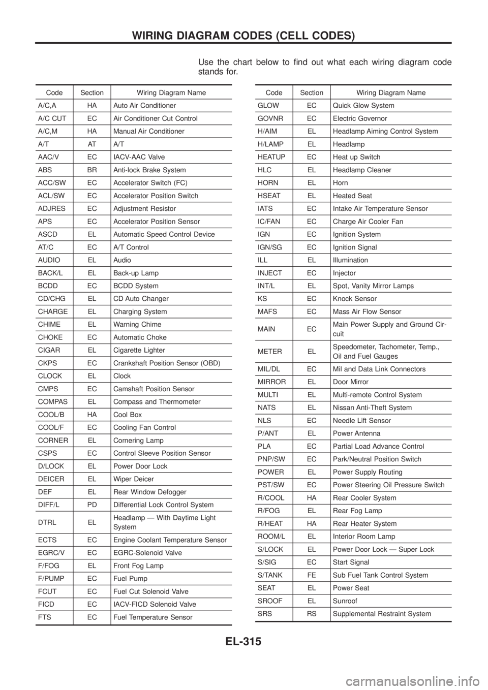
Use the chart below to ®nd out what each wiring diagram code
stands for.
Code Section Wiring Diagram Name
A/C,A HA Auto Air Conditioner
A/C CUT EC Air Conditioner Cut Control
A/C,M HA Manual Air Conditioner
A/T AT A/T
AAC/V EC IACV-AAC Valve
ABS BR Anti-lock Brake System
ACC/SW EC Accelerator Switch (FC)
ACL/SW EC Accelerator Position Switch
ADJRES EC Adjustment Resistor
APS EC Accelerator Position Sensor
ASCD EL Automatic Speed Control Device
AT/C EC A/T Control
AUDIO EL Audio
BACK/L EL Back-up Lamp
BCDD EC BCDD System
CD/CHG EL CD Auto Changer
CHARGE EL Charging System
CHIME EL Warning Chime
CHOKE EC Automatic Choke
CIGAR EL Cigarette Lighter
CKPS EC Crankshaft Position Sensor (OBD)
CLOCK EL Clock
CMPS EC Camshaft Position Sensor
COMPAS EL Compass and Thermometer
COOL/B HA Cool Box
COOL/F EC Cooling Fan Control
CORNER EL Cornering Lamp
CSPS EC Control Sleeve Position Sensor
D/LOCK EL Power Door Lock
DEICER EL Wiper Deicer
DEF EL Rear Window Defogger
DIFF/L PD Differential Lock Control System
DTRL ELHeadlamp Ð With Daytime Light
System
ECTS EC Engine Coolant Temperature Sensor
EGRC/V EC EGRC-Solenoid Valve
F/FOG EL Front Fog Lamp
F/PUMP EC Fuel Pump
FCUT EC Fuel Cut Solenoid Valve
FICD EC IACV-FICD Solenoid Valve
FTS EC Fuel Temperature SensorCode Section Wiring Diagram Name
GLOW EC Quick Glow System
GOVNR EC Electric Governor
H/AIM EL Headlamp Aiming Control System
H/LAMP EL Headlamp
HEATUP EC Heat up Switch
HLC EL Headlamp Cleaner
HORN EL Horn
HSEAT EL Heated Seat
IATS EC Intake Air Temperature Sensor
IC/FAN EC Charge Air Cooler Fan
IGN EC Ignition System
IGN/SG EC Ignition Signal
ILL EL Illumination
INJECT EC Injector
INT/L EL Spot, Vanity Mirror Lamps
KS EC Knock Sensor
MAFS EC Mass Air Flow Sensor
MAIN ECMain Power Supply and Ground Cir-
cuit
METER ELSpeedometer, Tachometer, Temp.,
Oil and Fuel Gauges
MIL/DL EC Mil and Data Link Connectors
MIRROR EL Door Mirror
MULTI EL Multi-remote Control System
NATS EL Nissan Anti-Theft System
NLS EC Needle Lift Sensor
P/ANT EL Power Antenna
PLA EC Partial Load Advance Control
PNP/SW EC Park/Neutral Position Switch
POWER EL Power Supply Routing
PST/SW EC Power Steering Oil Pressure Switch
R/COOL HA Rear Cooler System
R/FOG EL Rear Fog Lamp
R/HEAT HA Rear Heater System
ROOM/L EL Interior Room Lamp
S/LOCK EL Power Door Lock Ð Super Lock
S/SIG EC Start Signal
S/TANK FE Sub Fuel Tank Control System
SEAT EL Power Seat
SROOF EL Sunroof
SRS RS Supplemental Restraint System
WIRING DIAGRAM CODES (CELL CODES)
EL-315
Page 684 of 1226
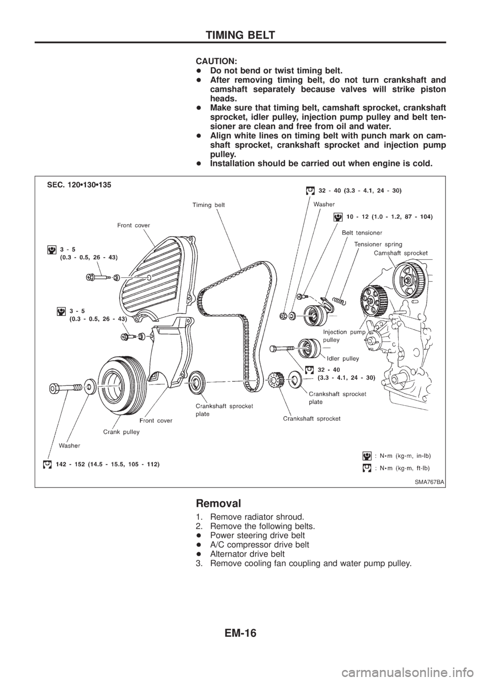
CAUTION:
+Do not bend or twist timing belt.
+After removing timing belt, do not turn crankshaft and
camshaft separately because valves will strike piston
heads.
+Make sure that timing belt, camshaft sprocket, crankshaft
sprocket, idler pulley, injection pump pulley and belt ten-
sioner are clean and free from oil and water.
+Align white lines on timing belt with punch mark on cam-
shaft sprocket, crankshaft sprocket and injection pump
pulley.
+Installation should be carried out when engine is cold.
Removal
1. Remove radiator shroud.
2. Remove the following belts.
+Power steering drive belt
+A/C compressor drive belt
+Alternator drive belt
3. Remove cooling fan coupling and water pump pulley.
SMA767BA
TIMING BELT
EM-16
Page 713 of 1226
Removal
1. Remove engine, transmission and transfer's undercovers, oil
pan guard and hood.
2. Drain engine coolant.
3. Remove charge air cooler assembly.
4. Remove vacuum hoses, fuel tubes, harnesses, and connectors
and so on.
5. Remove radiator assembly.
6. Remove drive belts.
7. Remove power steering oil pump, alternator and air conditioner
compressor.
8. Remove starter motor assembly.
9. Remove front exhaust tube.
10. Remove transmission from vehicle.
Refer to MT section.
11. Hoist engine with engine slingers and remove engine mounting
bolts from both sides.
12. Remove engine from vehicle.
Installation
+Install in reverse order of removal.
ENGINE REMOVAL
EM-45
Page 742 of 1226
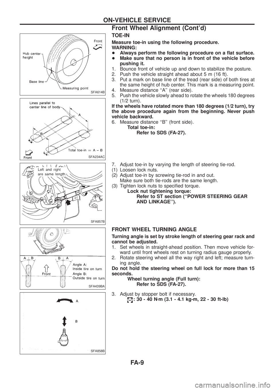
TOE-IN
Measure toe-in using the following procedure.
WARNING:
+Always perform the following procedure on a ¯at surface.
+Make sure that no person is in front of the vehicle before
pushing it.
1. Bounce front of vehicle up and down to stabilize the posture.
2. Push the vehicle straight ahead about 5 m (16 ft).
3. Put a mark on base line of the tread (rear side) of both tires at
the same height of hub center. This mark is a measuring point.
4. Measure distance ``A'' (rear side).
5. Push the vehicle slowly ahead to rotate the wheels 180 degrees
(1/2 turn).
If the wheels have rotated more than 180 degrees (1/2 turn), try
the above procedure again from the beginning. Never push
vehicle backward.
6. Measure distance ``B'' (front side).
Total toe-in:
Refer to SDS (FA-27).
7. Adjust toe-in by varying the length of steering tie-rod.
(1) Loosen lock nuts.
(2) Adjust toe-in by screwing tie-rod in and out.
Make sure both tie-rods are the same length.
(3) Tighten lock nuts to speci®ed torque.
Lock nut tightening torque:
Refer to ST section (``POWER STEERING GEAR
AND LINKAGE'').
FRONT WHEEL TURNING ANGLE
Turning angle is set by stroke length of steering gear rack and
cannot be adjusted.
1. Set wheels in straight-ahead position. Then move vehicle for-
ward until front wheels rest on turning radius gauge properly.
2. Rotate steering wheel all the way right and left; measure turn-
ing angle.
Do not hold the steering wheel on full lock for more than 15
seconds.
Wheel turning angle (Full turn):
Refer to SDS (FA-27).
3. Adjust by stopper bolt if necessary.
:30-40Nzm (3.1 - 4.1 kg-m, 22 - 30 ft-lb)
SFA614B
SFA234AC
SFA857B
SFA439BA
SFA858B
ON-VEHICLE SERVICE
Front Wheel Alignment (Cont'd)
FA-9
Page 760 of 1226
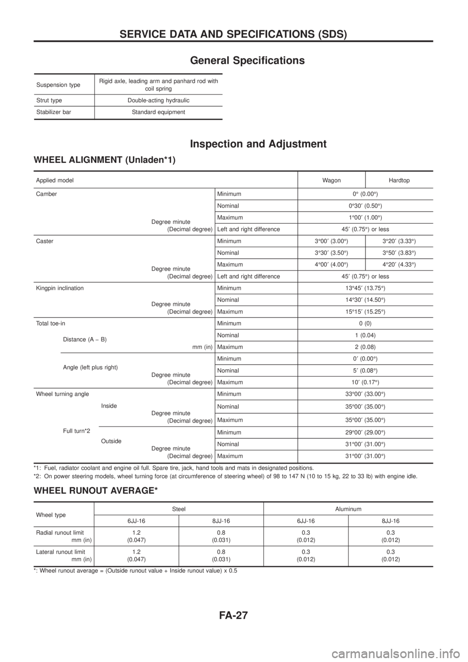
General Speci®cations
Suspension typeRigid axle, leading arm and panhard rod with
coil spring
Strut type Double-acting hydraulic
Stabilizer bar Standard equipment
Inspection and Adjustment
WHEEL ALIGNMENT (Unladen*1)
Applied modelWagon Hardtop
Camber Minimum 0É (0.00É)
Degree minute
(Decimal degree)Nominal 0É30¢(0.50É)
Maximum 1É00¢(1.00É)
Left and right difference 45¢(0.75É) or less
Caster Minimum 3É00¢(3.00É) 3É20¢(3.33É)
Degree minute
(Decimal degree)Nominal 3É30¢(3.50É) 3É50¢(3.83É)
Maximum 4É00¢(4.00É) 4É20¢(4.33É)
Left and right difference 45¢(0.75É) or less
Kingpin inclination Minimum 13É45¢(13.75É)
Degree minute
(Decimal degree)Nominal 14É30¢(14.50É)
Maximum 15É15¢(15.25É)
Total toe-in Minimum 0 (0)
Distance (A þ B)
mm (in)Nominal 1 (0.04)
Maximum 2 (0.08)
Angle (left plus right)
Degree minute
(Decimal degree)Minimum 0¢(0.00É)
Nominal 5¢(0.08É)
Maximum 10¢(0.17É)
Wheel turning angle Minimum 33É00¢(33.00É)
Full turn*2Inside
Degree minute
(Decimal degree)Nominal 35É00¢(35.00É)
Maximum 35É00¢(35.00É)
Outside
Degree minute
(Decimal degree)Minimum 29É00¢(29.00É)
Nominal 31É00¢(31.00É)
Maximum 31É00¢(31.00É)
*1: Fuel, radiator coolant and engine oil full. Spare tire, jack, hand tools and mats in designated positions.
*2: On power steering models, wheel turning force (at circumference of steering wheel) of 98 to 147 N (10 to 15 kg, 22 to 33 lb) with engine idle.
WHEEL RUNOUT AVERAGE*
Wheel typeSteel Aluminum
6JJ-16 8JJ-16 6JJ-16 8JJ-16
Radial runout limit
mm (in)1.2
(0.047)0.8
(0.031)0.3
(0.012)0.3
(0.012)
Lateral runout limit
mm (in)1.2
(0.047)0.8
(0.031)0.3
(0.012)0.3
(0.012)
*: Wheel runout average = (Outside runout value + Inside runout value) x 0.5
SERVICE DATA AND SPECIFICATIONS (SDS)
FA-27
Page 780 of 1226
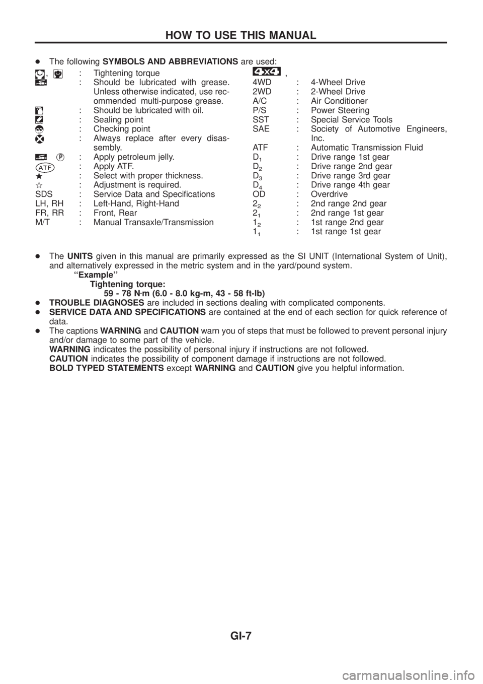
+The followingSYMBOLS AND ABBREVIATIONSare used:
,: Tightening torque
: Should be lubricated with grease.
Unless otherwise indicated, use rec-
ommended multi-purpose grease.
: Should be lubricated with oil.
: Sealing point
: Checking point
: Always replace after every disas-
sembly.
jP: Apply petroleum jelly.
: Apply ATF.
.: Select with proper thickness.
>: Adjustment is required.
SDS : Service Data and Speci®cations
LH, RH : Left-Hand, Right-Hand
FR, RR : Front, Rear
M/T : Manual Transaxle/Transmission
,
4WD : 4-Wheel Drive
2WD : 2-Wheel Drive
A/C : Air Conditioner
P/S : Power Steering
SST : Special Service Tools
SAE : Society of Automotive Engineers,
Inc.
ATF : Automatic Transmission Fluid
D
1: Drive range 1st gear
D
2: Drive range 2nd gear
D
3: Drive range 3rd gear
D
4: Drive range 4th gear
OD : Overdrive
2
2: 2nd range 2nd gear
2
1: 2nd range 1st gear
1
2: 1st range 2nd gear
1
1: 1st range 1st gear
+TheUNITSgiven in this manual are primarily expressed as the SI UNIT (International System of Unit),
and alternatively expressed in the metric system and in the yard/pound system.
``Example''
Tightening torque:
59-78Nzm (6.0 - 8.0 kg-m, 43 - 58 ft-lb)
+TROUBLE DIAGNOSESare included in sections dealing with complicated components.
+SERVICE DATA AND SPECIFICATIONSare contained at the end of each section for quick reference of
data.
+The captionsWARNINGandCAUTIONwarn you of steps that must be followed to prevent personal injury
and/or damage to some part of the vehicle.
WARNINGindicates the possibility of personal injury if instructions are not followed.
CAUTIONindicates the possibility of component damage if instructions are not followed.
BOLD TYPED STATEMENTSexceptWARNINGandCAUTIONgive you helpful information.
HOW TO USE THIS MANUAL
GI-7
Page 814 of 1226
Tow Truck Towing
CAUTION:
+All applicable local laws regarding the towing operation
must be obeyed.
+It is necessary to use proper towing equipment to avoid
possible damage to the vehicle during a towing operation.
+Attach safety chains for all towing.
+When towing, make sure that the transmission, steering
system and power train are in good order. If any unit is
damaged, a dolly must be used.
+When towing with the front wheels on the ground:
Turn the ignition key to the ``OFF'' position and secure the
steering wheel in a straight-ahead position with a rope or
similar device. Never place the ignition key in the ``LOCK''
position. This will result in damage to the steering lock
mechanism.
+When towing manual transmission models with the rear
wheels on the ground:
Release the parking brake and move the gearshift lever to
neutral (``N'' position).
+For 4-wheel drive models:
Set the manual-lock free-running hubs to the free position and
2-way lock free-running hubs to the auto position. (See
``
Transfer case shifting procedures for 4-wheel drive
vehicles'' in ``Starting and driving'' section.) Move the transfer
case shift lever into the ``2H'' position and the transmission shift
lever into the neutral (``N'') position.
Do not shift the transfer lever to the ``4L'' position. This will
cause damage to the transmission.
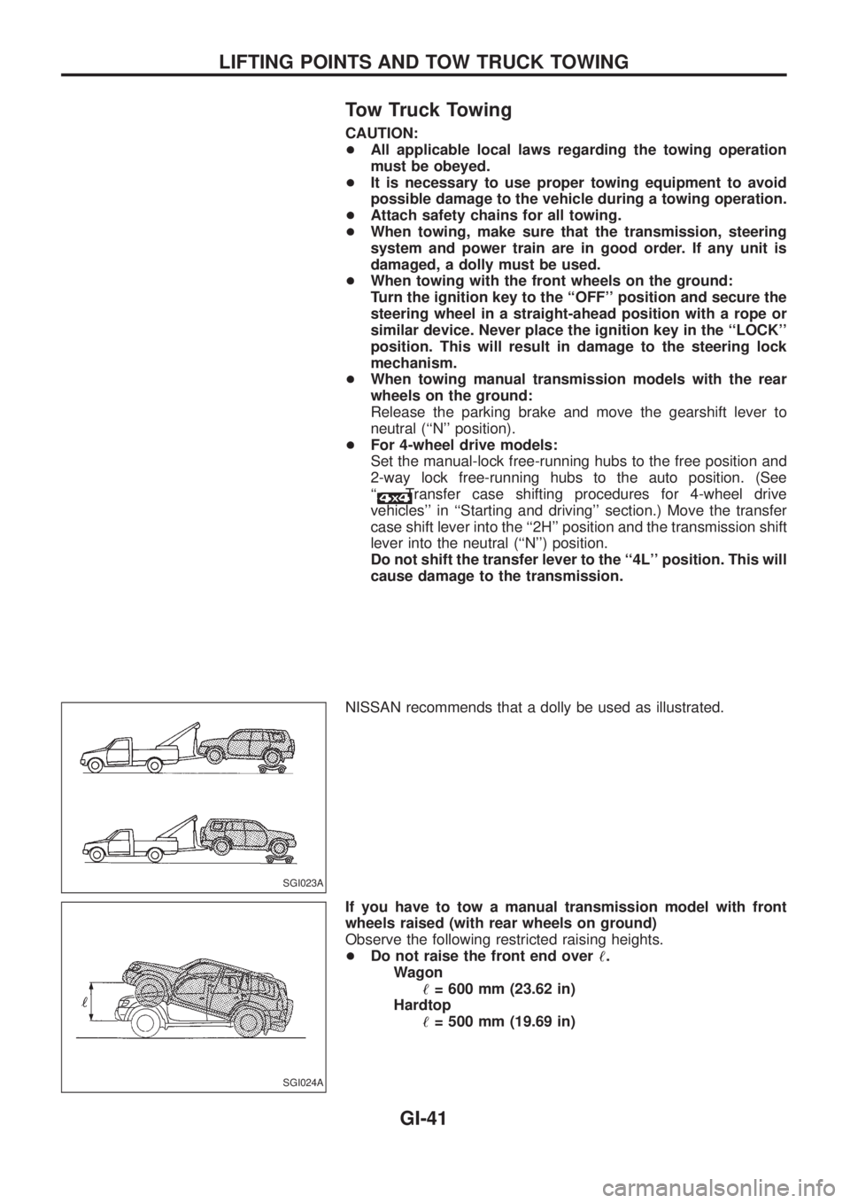
NISSAN recommends that a dolly be used as illustrated.
If you have to tow a manual transmission model with front
wheels raised (with rear wheels on ground)
Observe the following restricted raising heights.
+Do not raise the front end over!.
Wagon
!= 600 mm (23.62 in)
Hardtop
!= 500 mm (19.69 in)
SGI023A
SGI024A
LIFTING POINTS AND TOW TRUCK TOWING
GI-41
Page 952 of 1226
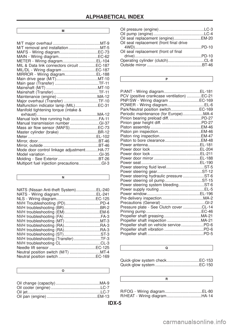
M
M/T major overhaul ..........................................MT-9
M/T removal and installation ............................MT-5
MAFS - Wiring diagram..................................EC-73
MAIN - Wiring diagram...................................EC-62
METER - Wiring diagram..............................EL-104
MIL & Data link connectors circuit ...............EC-187
MIL/DL - Wiring diagram ..............................EC-187
MIRROR - Wiring diagram............................EL-188
Main drive gear (M/T).....................................MT-10
Main gear (Transfer) .......................................TF-11
Mainshaft (M/T) ..............................................MT-10
Mainshaft (Transfer) ........................................TF-11
Maintenance (engine) ....................................MA-12
Major overhaul (Transfer) ...............................TF-10
Malfunction indicator lamp (MIL) ....................EC-31
Manifold tightening torque (intake &
exhaust)......................................................MA-12
Manual lock free running hub .........................FA-11
Manual transmission number ..........................GI-37
Mass air ¯ow sensor (MAFS).........................EC-73
Master cylinder (brake) ..................................BR-12
Meter .............................................................EL-102
Mirror, door......................................................BT-46
Mirror, outside .................................................BT-46
Mode door control linkage adjustment ...........HA-77
Model variation ................................................GI-35
Molding - See Exterior ....................................BT-26
Multiport fuel injection precautions ....................GI-3
N
NATS (Nissan Anti-theft System)..................EL-240
NATS - Wiring diagram .................................EL-241
NLS - Wiring diagram...................................EC-125
NVH Troubleshooting (PD)...............................PD-4
NVH troubleshooting (BR)................................BR-2
NVH troubleshooting (EM) ...............................EM-6
NVH troubleshooting (FA) .................................FA-3
NVH troubleshooting (MT) ...............................MT-3
NVH troubleshooting (RA)................................RA-3
NVH troubleshooting (RA)................................RA-3
NVH troubleshooting (ST).................................ST-3
NVH troubleshooting (Transfer) ........................TF-3
NVH troubleshooting CL ...................................CL-3
Needle lift sensor .........................................EC-125
Neutral position switch (M/T) ...........................MT-4
Neutral position switch .................................EC-169
O
Oil change (capacity) .......................................MA-9
Oil cooler (engine) ............................................LC-7
Oil jet.................................................................LC-7
Oil pan (engine) .............................................EM-13Oil pressure (engine) ........................................LC-3
Oil pump (engine) .............................................LC-4
Oil seal replacement (engine)........................EM-20
Oil seal replacement (front ®nal drive
4WD)...........................................................PD-10
Oil seal replacement (front of ®nal
drive) ...........................................................PD-10
Operating cylinder (clutch)................................CL-8
Outside mirror .................................................BT-46
P
P/ANT - Wiring diagram................................EL-181
PCV (positive crankcase ventilation) .............EC-21
PNP/SW - Wiring diagram ...........................EC-169
POWER - Wiring diagram.................................EL-6
Park/Neutral position switch .........................EC-169
Periodic maintenance (for Europe) ..................MA-4
Pinion bearing preload diff. ............................PD-27
Pinion gear height diff. ...................................PD-27
Piston assembly .............................................EM-46
Piston pin inspection ......................................EM-46
Piston ring inspection.....................................EM-47
Piston to bore clearance ................................EM-48
Power antenna ..............................................EL-181
Power door lock ............................................EL-204
Power door lock ............................................EL-211
Power door mirror .........................................EL-188
Power seat ....................................................EL-190
Power steering ¯uid level..................................ST-5
Power steering gear........................................ST-12
Power steering hydraulic pressure ...................ST-6
Power steering oil pump .................................ST-15
Power steering system bleeding.......................ST-6
Power supply routing ........................................EL-5
Power window ...............................................EL-196
Pre-delivery inspection.....................................MA-2
Precautions (General) .......................................GI-2
Pressure plate - See Clutch cover .................CL-14
Priming pump .................................................EC-46
Propeller shaft greasing .................................MA-21
Propeller shaft inspection ..............................MA-21
Propeller shaft on vehicle service ....................PD-6
Propeller shaft vibration ...................................PD-6
Propeller shaft ..................................................PD-5
Q
Quick-glow system check.............................EC-153
Quick-glow system .......................................EC-150
R
R/FOG - Wiring diagram .................................EL-80
R/HEAT - Wiring diagram ...............................HA-14
ALPHABETICAL INDEX
IDX-5
Page 977 of 1226
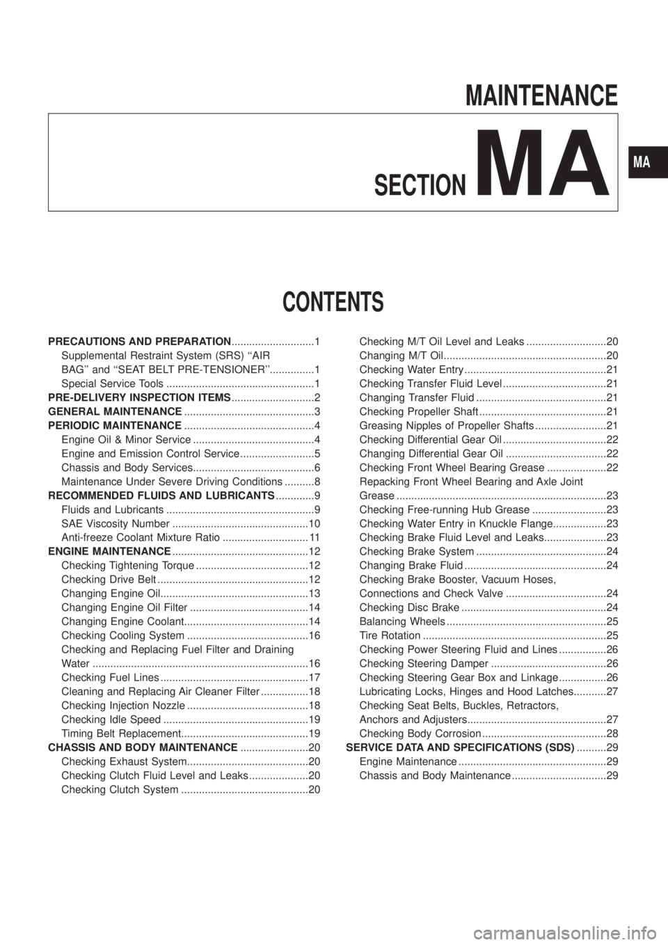
MAINTENANCE
SECTION
MA
CONTENTS
PRECAUTIONS AND PREPARATION............................1
Supplemental Restraint System (SRS) ``AIR
BAG'' and ``SEAT BELT PRE-TENSIONER''...............1
Special Service Tools ..................................................1
PRE-DELIVERY INSPECTION ITEMS............................2
GENERAL MAINTENANCE............................................3
PERIODIC MAINTENANCE............................................4
Engine Oil & Minor Service .........................................4
Engine and Emission Control Service .........................5
Chassis and Body Services.........................................6
Maintenance Under Severe Driving Conditions ..........8
RECOMMENDED FLUIDS AND LUBRICANTS.............9
Fluids and Lubricants ..................................................9
SAE Viscosity Number ..............................................10
Anti-freeze Coolant Mixture Ratio ............................. 11
ENGINE MAINTENANCE..............................................12
Checking Tightening Torque ......................................12
Checking Drive Belt ...................................................12
Changing Engine Oil..................................................13
Changing Engine Oil Filter ........................................14
Changing Engine Coolant..........................................14
Checking Cooling System .........................................16
Checking and Replacing Fuel Filter and Draining
Water .........................................................................16
Checking Fuel Lines ..................................................17
Cleaning and Replacing Air Cleaner Filter ................18
Checking Injection Nozzle .........................................18
Checking Idle Speed .................................................19
Timing Belt Replacement...........................................19
CHASSIS AND BODY MAINTENANCE.......................20
Checking Exhaust System.........................................20
Checking Clutch Fluid Level and Leaks ....................20
Checking Clutch System ...........................................20Checking M/T Oil Level and Leaks ...........................20
Changing M/T Oil.......................................................20
Checking Water Entry ................................................21
Checking Transfer Fluid Level ...................................21
Changing Transfer Fluid ............................................21
Checking Propeller Shaft ...........................................21
Greasing Nipples of Propeller Shafts ........................21
Checking Differential Gear Oil ...................................22
Changing Differential Gear Oil ..................................22
Checking Front Wheel Bearing Grease ....................22
Repacking Front Wheel Bearing and Axle Joint
Grease .......................................................................23
Checking Free-running Hub Grease .........................23
Checking Water Entry in Knuckle Flange..................23
Checking Brake Fluid Level and Leaks.....................23
Checking Brake System ............................................24
Changing Brake Fluid ................................................24
Checking Brake Booster, Vacuum Hoses,
Connections and Check Valve ..................................24
Checking Disc Brake .................................................24
Balancing Wheels ......................................................25
Tire Rotation ..............................................................25
Checking Power Steering Fluid and Lines ................26
Checking Steering Damper .......................................26
Checking Steering Gear Box and Linkage ................26
Lubricating Locks, Hinges and Hood Latches...........27
Checking Seat Belts, Buckles, Retractors,
Anchors and Adjusters...............................................27
Checking Body Corrosion ..........................................28
SERVICE DATA AND SPECIFICATIONS (SDS)..........29
Engine Maintenance ..................................................29
Chassis and Body Maintenance ................................29
MA