rear bumper NISSAN PATROL 2006 Service Manual
[x] Cancel search | Manufacturer: NISSAN, Model Year: 2006, Model line: PATROL, Model: NISSAN PATROL 2006Pages: 1226, PDF Size: 37.18 MB
Page 84 of 1226
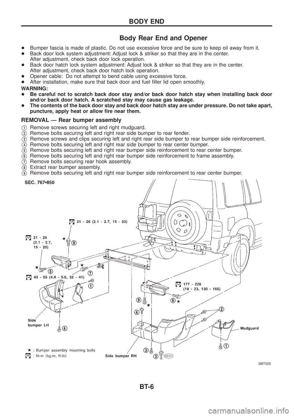
Body Rear End and Opener
+Bumper fascia is made of plastic. Do not use excessive force and be sure to keep oil away from it.
+Back door lock system adjustment: Adjust lock & striker so that they are in the center.
After adjustment, check back door lock operation.
+Back door hatch lock system adjustment: Adjust lock & striker so that they are in the center.
After adjustment, check back door hatch lock operation.
+Opener cable: Do not attempt to bend cable using excessive force.
+After installation, make sure that back door and fuel ®ller lid open smoothly.
WARNING:
+Be careful not to scratch back door stay and/or back door hatch stay when installing back door
and/or back door hatch. A scratched stay may cause gas leakage.
+The contents of the back door stay and back door hatch stay are under pressure. Do not take apart,
puncture, apply heat or allow ®re near them.
REMOVAL Ð Rear bumper assembly
V1Remove screws securing left and right mudguard.
V2Remove bolts securing left and right rear side bumper to rear fender.
V3Remove screws and clips securing left and right rear side bumper to rear bumper side reinforcement.
V4Remove bolts securing left and right rear side bumper to rear center bumper.
V5Remove bolts securing left and right rear bumper side reinforcement to rear center bumper.
V6Remove bolts securing left and right rear bumper side reinforcement to frame assembly.
V7Remove bolts securing rear hook assembly.
V8Extract rear bumper assembly.
V9Remove bolts securing left and right rear bumper side reinforcement to rear center bumper.
SBT520
BODY END
BT-6
Page 418 of 1226
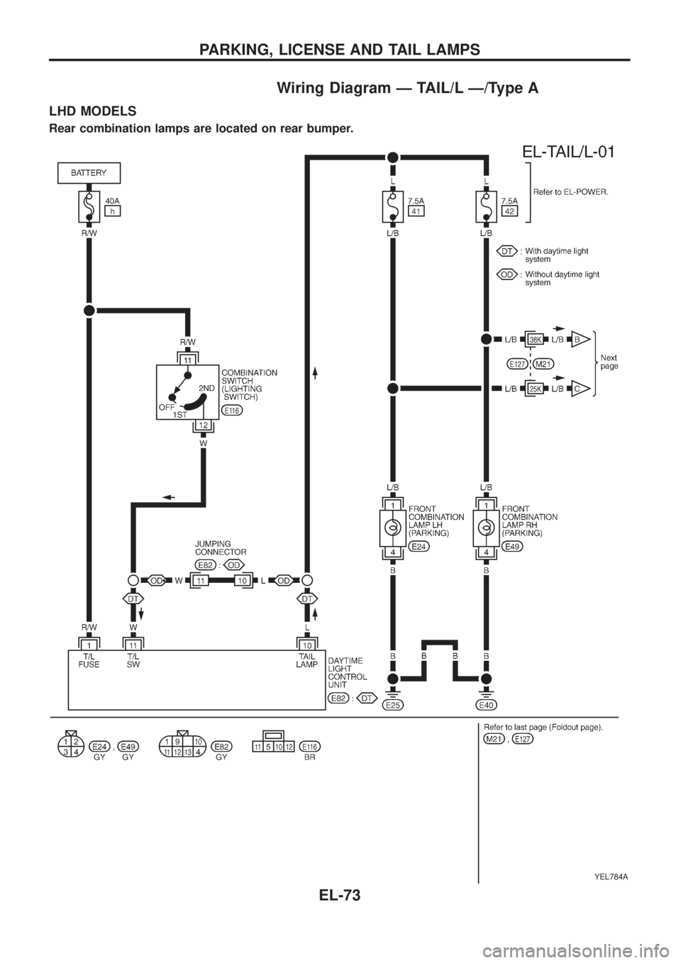
Wiring Diagram Ð TAIL/L Ð/Type A
LHD MODELS
Rear combination lamps are located on rear bumper.
YEL784A
PARKING, LICENSE AND TAIL LAMPS
EL-73
Page 420 of 1226
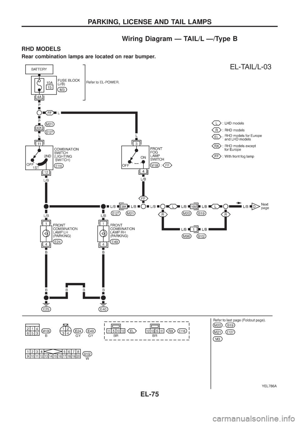
Wiring Diagram Ð TAIL/L Ð/Type B
RHD MODELS
Rear combination lamps are located on rear bumper.
YEL786A
PARKING, LICENSE AND TAIL LAMPS
EL-75
Page 422 of 1226
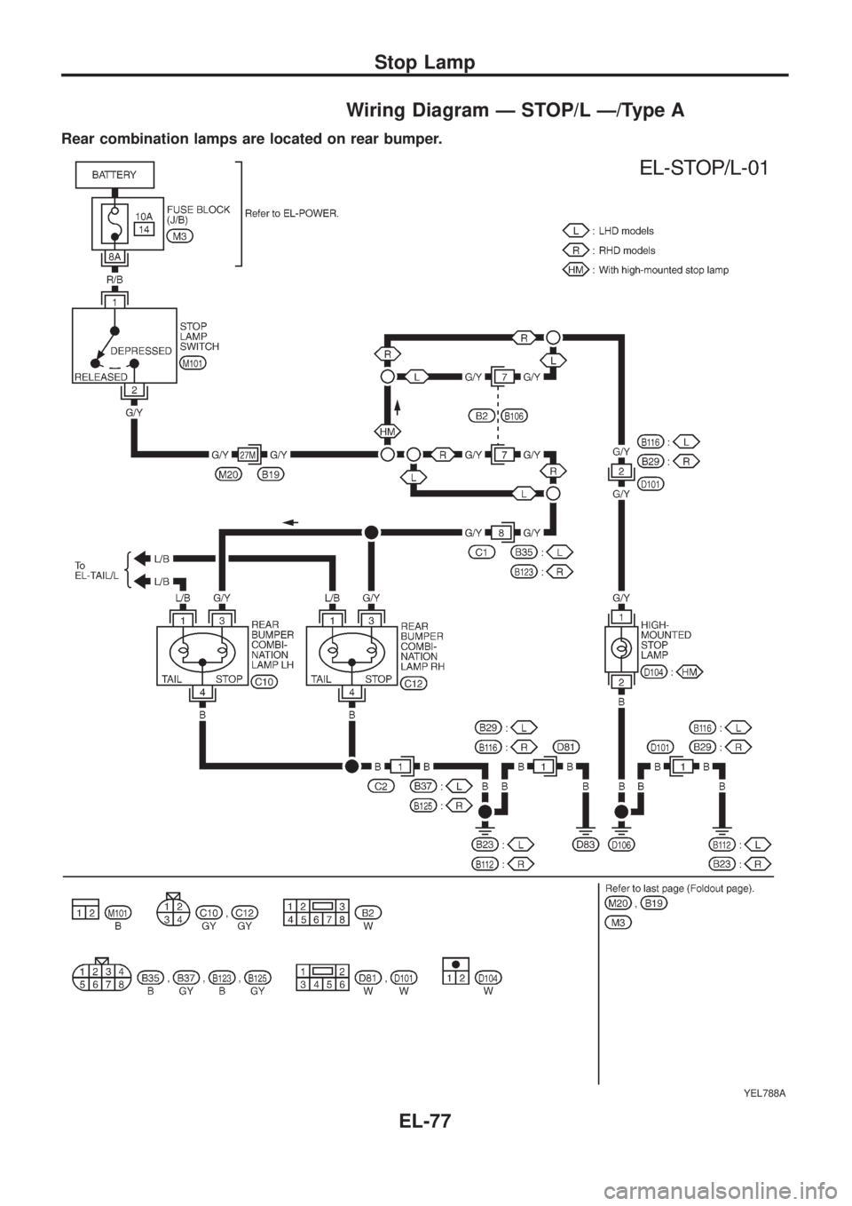
Wiring Diagram Ð STOP/L Ð/Type A
Rear combination lamps are located on rear bumper.
YEL788A
Stop Lamp
EL-77
Page 426 of 1226
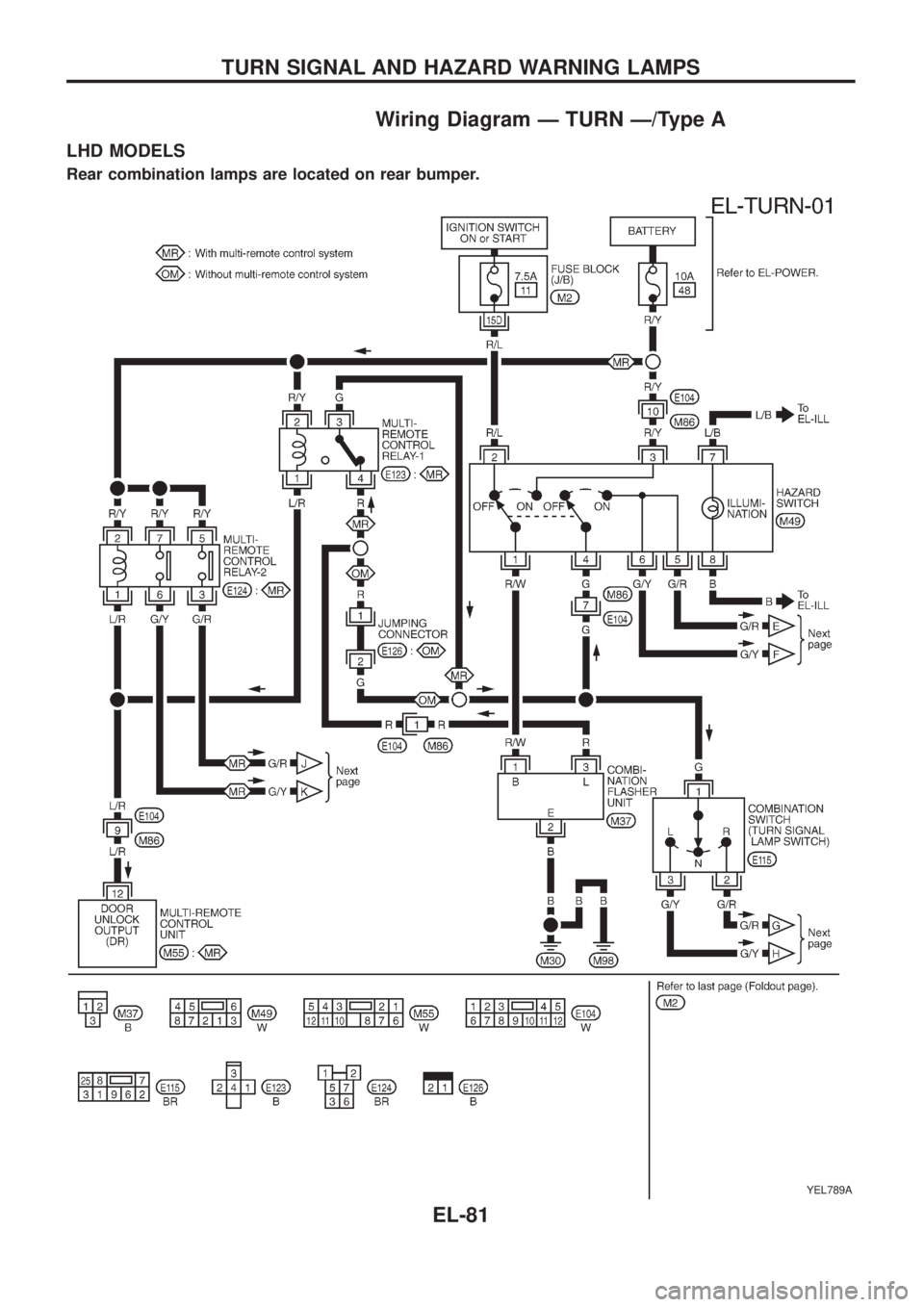
Wiring Diagram Ð TURN Ð/Type A
LHD MODELS
Rear combination lamps are located on rear bumper.
YEL789A
TURN SIGNAL AND HAZARD WARNING LAMPS
EL-81
Page 428 of 1226
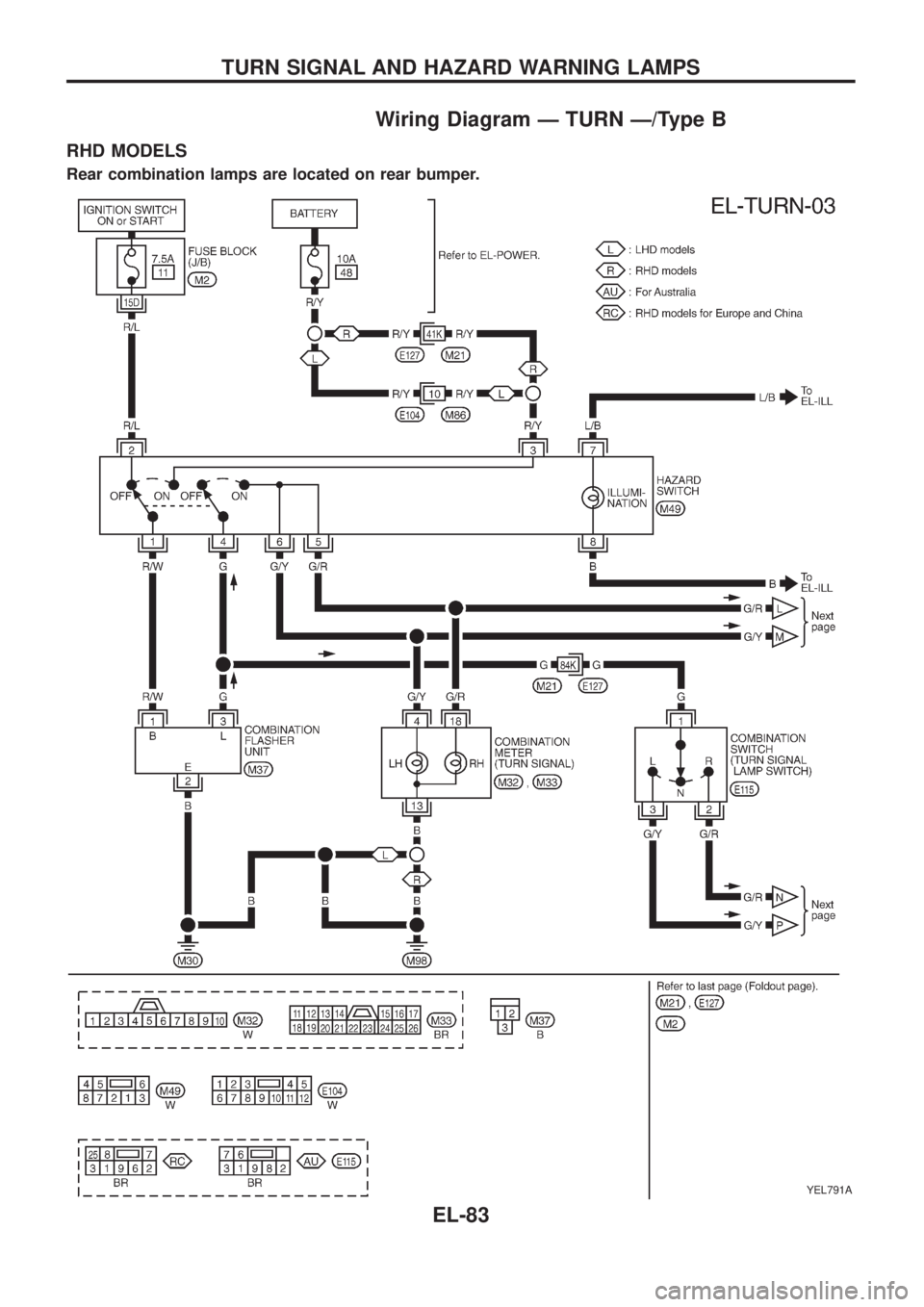
Wiring Diagram Ð TURN Ð/Type B
RHD MODELS
Rear combination lamps are located on rear bumper.
YEL791A
TURN SIGNAL AND HAZARD WARNING LAMPS
EL-83
Page 659 of 1226
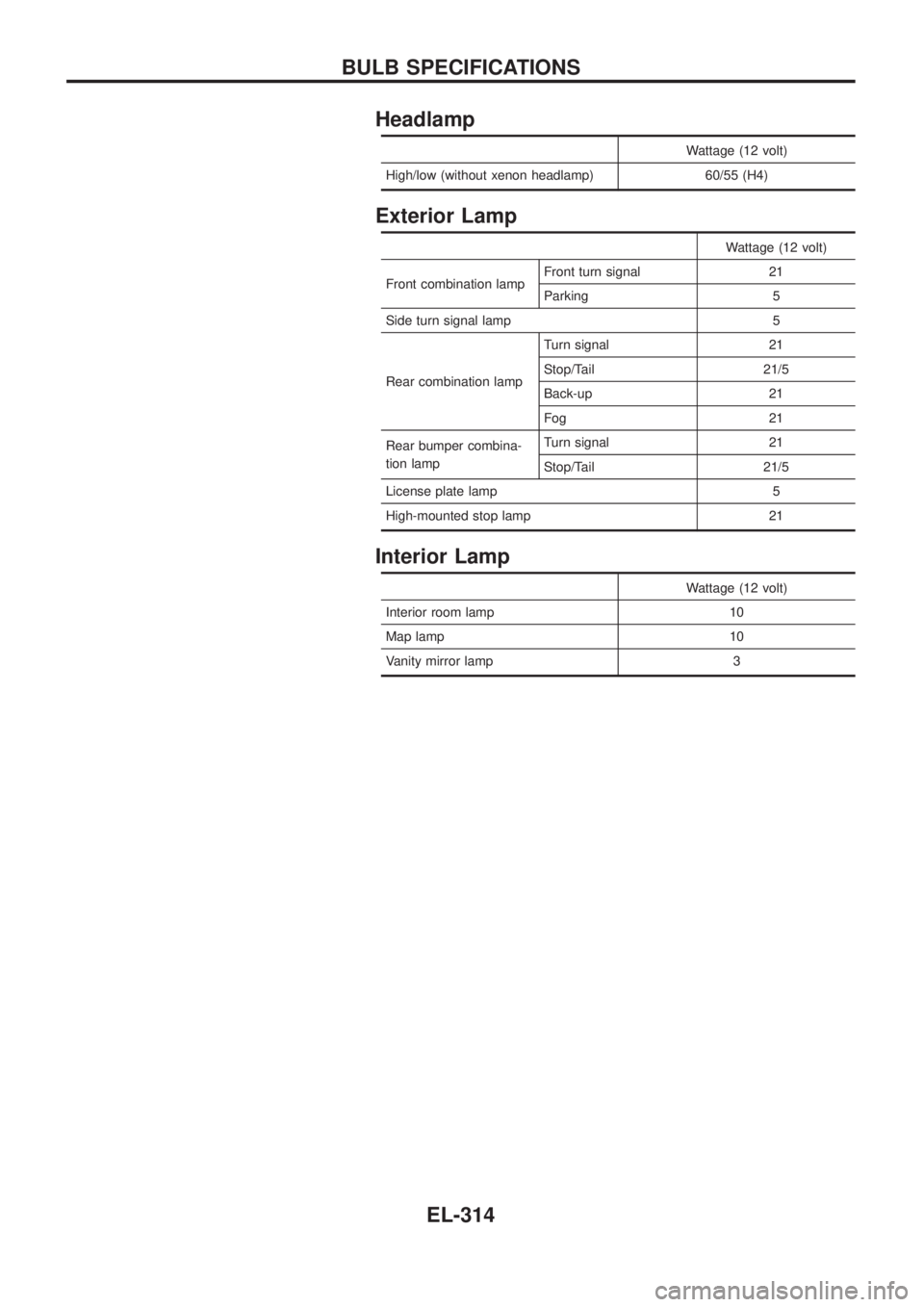
Headlamp
Wattage (12 volt)
High/low (without xenon headlamp) 60/55 (H4)
Exterior Lamp
Wattage (12 volt)
Front combination lampFront turn signal 21
Parking 5
Side turn signal lamp 5
Rear combination lampTurn signal 21
Stop/Tail 21/5
Back-up 21
Fog 21
Rear bumper combina-
tion lampTurn signal 21
Stop/Tail 21/5
License plate lamp 5
High-mounted stop lamp 21
Interior Lamp
Wattage (12 volt)
Interior room lamp 10
Map lamp 10
Vanity mirror lamp 3
BULB SPECIFICATIONS
EL-314
Page 949 of 1226
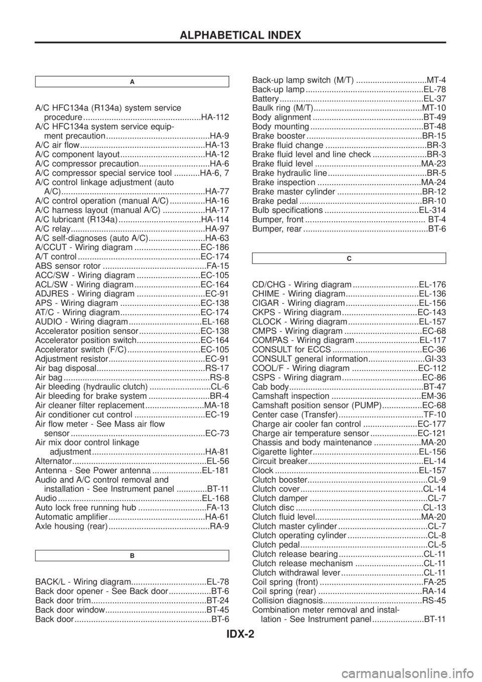
A
A/C HFC134a (R134a) system service
procedure ..................................................HA-112
A/C HFC134a system service equip-
ment precaution ............................................HA-9
A/C air ¯ow .....................................................HA-13
A/C component layout ....................................HA-12
A/C compressor precaution..............................HA-6
A/C compressor special service tool ...........HA-6, 7
A/C control linkage adjustment (auto
A/C).............................................................HA-77
A/C control operation (manual A/C) ...............HA-16
A/C harness layout (manual A/C) ..................HA-17
A/C lubricant (R134a) ...................................HA-114
A/C relay.........................................................HA-97
A/C self-diagnoses (auto A/C)........................HA-63
A/CCUT - Wiring diagram ............................EC-186
A/T control ....................................................EC-174
ABS sensor rotor ............................................FA-15
ACC/SW - Wiring diagram ...........................EC-105
ACL/SW - Wiring diagram ............................EC-164
ADJRES - Wiring diagram .............................EC-91
APS - Wiring diagram ..................................EC-138
AT/C - Wiring diagram..................................EC-174
AUDIO - Wiring diagram ...............................EL-168
Accelerator position sensor ..........................EC-138
Accelerator position switch...........................EC-164
Accelerator switch (F/C) ...............................EC-105
Adjustment resistor.........................................EC-91
Air bag disposal..............................................RS-17
Air bag ..............................................................RS-8
Air bleeding (hydraulic clutch) ..........................CL-6
Air bleeding for brake system ..........................BR-4
Air cleaner ®lter replacement .........................MA-18
Air conditioner cut control ..............................EC-19
Air ¯ow meter - See Mass air ¯ow
sensor .........................................................EC-73
Air mix door control linkage
adjustment ................................................HA-81
Alternator.........................................................EL-56
Antenna - See Power antenna .....................EL-181
Audio and A/C control removal and
installation - See Instrument panel .............BT-11
Audio .............................................................EL-168
Auto lock free running hub .............................FA-13
Automatic ampli®er .........................................HA-61
Axle housing (rear) ...........................................RA-9
B
BACK/L - Wiring diagram................................EL-78
Back door opener - See Back door ..................BT-6
Back door trim.................................................BT-24
Back door window...........................................BT-45
Back door ..........................................................BT-6Back-up lamp switch (M/T) ..............................MT-4
Back-up lamp ..................................................EL-78
Battery .............................................................EL-37
Baulk ring (M/T)..............................................MT-10
Body alignment ...............................................BT-49
Body mounting ................................................BT-48
Brake booster .................................................BR-15
Brake ¯uid change ...........................................BR-3
Brake ¯uid level and line check .......................BR-3
Brake ¯uid level .............................................MA-23
Brake hydraulic line ..........................................BR-5
Brake inspection ............................................MA-24
Brake master cylinder ....................................BR-12
Brake pedal ....................................................BR-10
Bulb speci®cations ........................................EL-314
Bumper, front ................................................... BT-4
Bumper, rear .....................................................BT-6
C
CD/CHG - Wiring diagram ............................EL-176
CHIME - Wiring diagram...............................EL-136
CIGAR - Wiring diagram ...............................EL-156
CKPS - Wiring diagram ................................EC-143
CLOCK - Wiring diagram ..............................EL-157
CMPS - Wiring diagram .................................EC-68
COMPAS - Wiring diagram ...........................EL-117
CONSULT for ECCS ......................................EC-36
CONSULT general information ........................GI-33
COOL/F - Wiring diagram ............................EC-112
CSPS - Wiring diagram ..................................EC-86
Cab body.........................................................BT-47
Camshaft inspection ......................................EM-36
Camshaft position sensor (PUMP).................EC-68
Center case (Transfer) ....................................TF-10
Charge air cooler fan control .......................EC-177
Charge air temperature sensor ....................EC-121
Chassis and body maintenance ....................MA-20
Cigarette lighter.............................................EL-156
Circuit breaker.................................................EL-14
Clock .............................................................EL-157
Clutch booster...................................................CL-9
Clutch cover ....................................................CL-14
Clutch damper ..................................................CL-7
Clutch disc ......................................................CL-13
Clutch ¯uid level.............................................MA-20
Clutch master cylinder ......................................CL-7
Clutch operating cylinder ..................................CL-8
Clutch pedal ......................................................CL-5
Clutch release bearing ....................................CL-11
Clutch release mechanism .............................CL-11
Clutch withdrawal lever ...................................CL-11
Coil spring (front) ............................................FA-25
Coil spring (rear) ............................................RA-14
Collision diagnosis..........................................RS-45
Combination meter removal and instal-
lation - See Instrument panel ......................BT-11
ALPHABETICAL INDEX
IDX-2
Page 950 of 1226
Combination meter........................................EL-102
Combination switch .........................................EL-57
Combustion chamber replacement ................EM-32
Compass .......................................................EL-116
Compression pressure ...................................EM-10
Compressor special service tool ......................HA-6
Connecting rod...............................................EM-47
Connecting rod...............................................EM-51
Connector inspection .......................................GI-17
Console box - See Instrument panel ..............BT-11
Control lever (Transfer) .....................................TF-9
Control sleeve position sensor .......................EC-86
Coolant mixture ratio ......................................MA-11
Coolant replacement ......................................MA-14
Cooling circuit (engine) .....................................LC-9
Cooling fan control .......................................EC-112
Cooling fan motor .........................................EC-120
Cooling fan relay ..........................................EC-120
Cooling fan......................................................LC-15
Counter gear (M/T).........................................MT-10
Counter gear (Transfer) ..................................TF-11
Coupling sleeve (M/T) ....................................MT-10
Crankcase emission control system -
See Positive crankcase ventilation.............EC-21
Crankcase ventilation system - See
Positive crankcase ventilation ....................EC-21
Crankshaft position sensor (TDC)................EC-143
Crankshaft ......................................................EM-50
Cylinder block ..........................................EM-45, 48
Cylinder head .................................................EM-28
D
D/LOCK - Wiring diagram .............................EL-205
DEF - Wiring diagram ...................................EL-159
DEICER - Wiring diagram.............................EL-167
DTRL - Wiring diagram ...................................EL-67
Data link connector for Consult......................EC-36
Daytime light system.......................................EL-65
Diagnosis sensor unit .....................................RS-12
Diagnostic trouble code (DTC) for
ECCS OBD system ....................................EC-30
Differential carrier assembly...........................PD-31
Differential carrier disassembly ......................PD-14
Differential gear oil replacement ....................MA-22
Dimensions ......................................................GI-38
Dome light - See Interior lamp .......................EL-93
Door glass .........................................................BT-9
Door lock ...........................................................BT-9
Door mirror ......................................................BT-46
Door trim .........................................................BT-18
Door, front .........................................................BT-9
Door, rear ........................................................BT-10
Drive belt inspection ......................................MA-12
Drive chain (Transfer) .....................................TF-11
Drive pinion diff. inspection ............................PD-19
Drive pinion height .........................................PD-27
Drive shaft (front) ............................................FA-23
Dual pressure switch ......................................HA-11Dual pressure switch ......................................HA-97
E
ECCS basic inspection...................................EC-46
ECCS circuit diagram .....................................EC-11
ECCS component parts location ......................EC-8
ECCS on board diagnostic system ................EC-30
ECCS symptom matrix chart..........................EC-48
ECCS system diagram and chart ..................EC-12
ECCS-D control module .........................EC-54, 110
ECM input/output signal .................................EC-54
ECTS - Wiring diagram ..................................EC-78
EGR control (EGRC) - solenoid valve .........EC-155
EGR control valve ........................................EC-161
EGRC/V - Wiring diagram ............................EC-155
Electric governor ....................................EC-95, 148
Electric sunroof .............................................EL-186
Electrical diagnoses.........................................GI-20
Electrical unit.................................................EL-321
Electrical units location .................................EL-269
Electronic fuel injection pump ........................EC-27
Engine compartment .......................................BT-49
Engine coolant temperature sensor
(ECTS) ........................................................EC-78
Engine oil ®lter replacement ..........................MA-14
Engine oil precautions .......................................GI-4
Engine oil replacement ..................................MA-13
Engine outer component parts ........................EM-8
Engine removal ..............................................EM-43
Engine room - See Engine
compartment ...............................................BT-49
Engine serial number ......................................GI-37
Exhaust system inspection ............................MA-20
Exhaust system ................................................FE-3
Exterior ............................................................BT-26
F
FCUT - Wiring diagram ................................EC-129
FTS - Wiring diagram ...................................EC-134
Fan control amp. ............................................HA-88
Final drive disassembly ..................................PD-14
Final drive removal and installation................PD-11
Finisher, interior - See Trim ............................BT-14
Floor trim .........................................................BT-14
Flow charts ......................................................GI-30
Fluids................................................................MA-9
Flywheel (clutch).......................................CL-13, 14
Flywheel runout..............................................EM-52
Fog lamp, rear ................................................EL-80
Fork rod (M/T) ................................................MT-12
Front axle ........................................................FA-10
Front bumper ....................................................BT-4
Front case (Transfer) ......................................TF-10
Front disc brake .............................................BR-20
Front door .........................................................BT-9
ALPHABETICAL INDEX
IDX-3
Page 953 of 1226
ROOM/L - Wiring diagram ..............................EL-95
Radiator ..........................................................LC-14
Radio - See Audio.........................................EL-168
Rear axle (disc brake type) ..............................RA-6
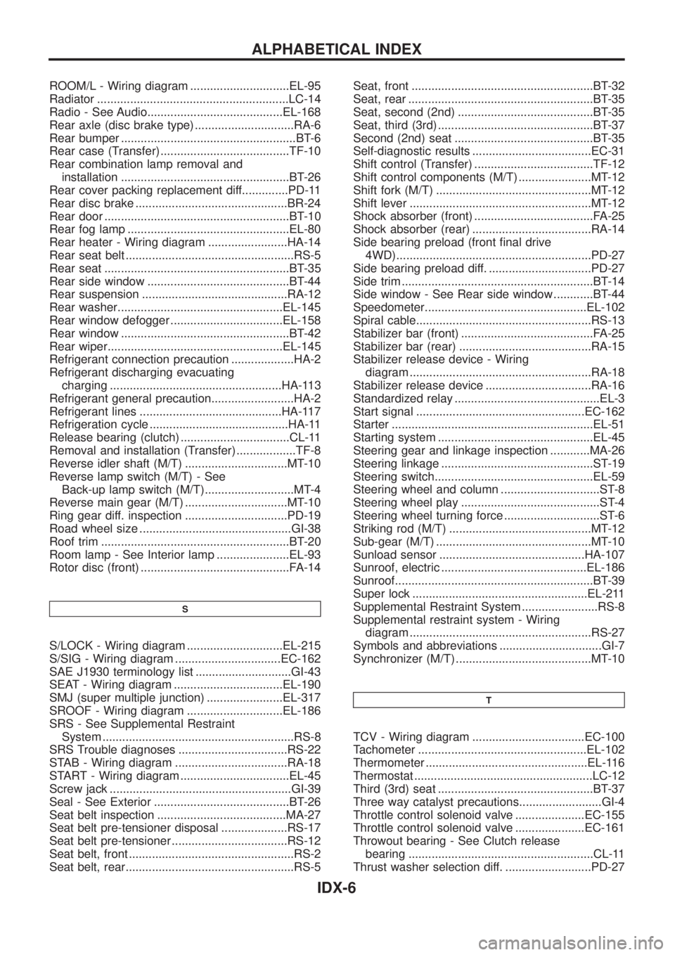
Rear bumper .....................................................BT-6
Rear case (Transfer) .......................................TF-10
Rear combination lamp removal and
installation ...................................................BT-26
Rear cover packing replacement diff..............PD-11
Rear disc brake ..............................................BR-24
Rear door ........................................................BT-10
Rear fog lamp .................................................EL-80
Rear heater - Wiring diagram ........................HA-14
Rear seat belt ...................................................RS-5
Rear seat ........................................................BT-35
Rear side window ...........................................BT-44
Rear suspension ............................................RA-12
Rear washer..................................................EL-145
Rear window defogger ..................................EL-158
Rear window ...................................................BT-42
Rear wiper.....................................................EL-145
Refrigerant connection precaution ...................HA-2
Refrigerant discharging evacuating
charging ....................................................HA-113
Refrigerant general precaution.........................HA-2
Refrigerant lines ...........................................HA-117
Refrigeration cycle ..........................................HA-11
Release bearing (clutch) .................................CL-11
Removal and installation (Transfer) ..................TF-8
Reverse idler shaft (M/T) ...............................MT-10
Reverse lamp switch (M/T) - See
Back-up lamp switch (M/T)...........................MT-4
Reverse main gear (M/T) ...............................MT-10
Ring gear diff. inspection ...............................PD-19
Road wheel size ..............................................GI-38
Roof trim .........................................................BT-20
Room lamp - See Interior lamp ......................EL-93
Rotor disc (front) .............................................FA-14
S
S/LOCK - Wiring diagram .............................EL-215
S/SIG - Wiring diagram ................................EC-162
SAE J1930 terminology list .............................GI-43
SEAT - Wiring diagram .................................EL-190
SMJ (super multiple junction) .......................EL-317
SROOF - Wiring diagram .............................EL-186
SRS - See Supplemental Restraint
System ..........................................................RS-8
SRS Trouble diagnoses .................................RS-22
STAB - Wiring diagram ..................................RA-18
START - Wiring diagram .................................EL-45
Screw jack .......................................................GI-39
Seal - See Exterior .........................................BT-26
Seat belt inspection .......................................MA-27
Seat belt pre-tensioner disposal ....................RS-17
Seat belt pre-tensioner ...................................RS-12
Seat belt, front ..................................................RS-2
Seat belt, rear...................................................RS-5Seat, front .......................................................BT-32
Seat, rear ........................................................BT-35
Seat, second (2nd) .........................................BT-35
Seat, third (3rd) ...............................................BT-37
Second (2nd) seat ..........................................BT-35
Self-diagnostic results ....................................EC-31
Shift control (Transfer) ....................................TF-12
Shift control components (M/T) ......................MT-12
Shift fork (M/T) ...............................................MT-12
Shift lever .......................................................MT-12
Shock absorber (front) ....................................FA-25
Shock absorber (rear) ....................................RA-14
Side bearing preload (front ®nal drive
4WD)...........................................................PD-27
Side bearing preload diff. ...............................PD-27
Side trim ..........................................................BT-14
Side window - See Rear side window ............BT-44
Speedometer.................................................EL-102
Spiral cable.....................................................RS-13
Stabilizer bar (front) ........................................FA-25
Stabilizer bar (rear) ........................................RA-15
Stabilizer release device - Wiring
diagram .......................................................RA-18
Stabilizer release device ................................RA-16
Standardized relay ............................................EL-3
Start signal ...................................................EC-162
Starter .............................................................EL-51
Starting system ...............................................EL-45
Steering gear and linkage inspection ............MA-26
Steering linkage ..............................................ST-19
Steering switch................................................EL-59
Steering wheel and column ..............................ST-8
Steering wheel play ..........................................ST-4
Steering wheel turning force .............................ST-6
Striking rod (M/T) ...........................................MT-12
Sub-gear (M/T) ...............................................MT-10
Sunload sensor ............................................HA-107
Sunroof, electric ............................................EL-186
Sunroof............................................................BT-39
Super lock .....................................................EL-211
Supplemental Restraint System .......................RS-8
Supplemental restraint system - Wiring
diagram .......................................................RS-27
Symbols and abbreviations ...............................GI-7
Synchronizer (M/T) .........................................MT-10
T
TCV - Wiring diagram ..................................EC-100
Tachometer ...................................................EL-102
Thermometer .................................................EL-116
Thermostat ......................................................LC-12
Third (3rd) seat ...............................................BT-37
Three way catalyst precautions.........................GI-4
Throttle control solenoid valve .....................EC-155
Throttle control solenoid valve .....................EC-161
Throwout bearing - See Clutch release
bearing ........................................................CL-11
Thrust washer selection diff. ..........................PD-27
ALPHABETICAL INDEX
IDX-6