transmission oil NISSAN PATROL 2006 Service Manual
[x] Cancel search | Manufacturer: NISSAN, Model Year: 2006, Model line: PATROL, Model: NISSAN PATROL 2006Pages: 1226, PDF Size: 37.18 MB
Page 691 of 1226
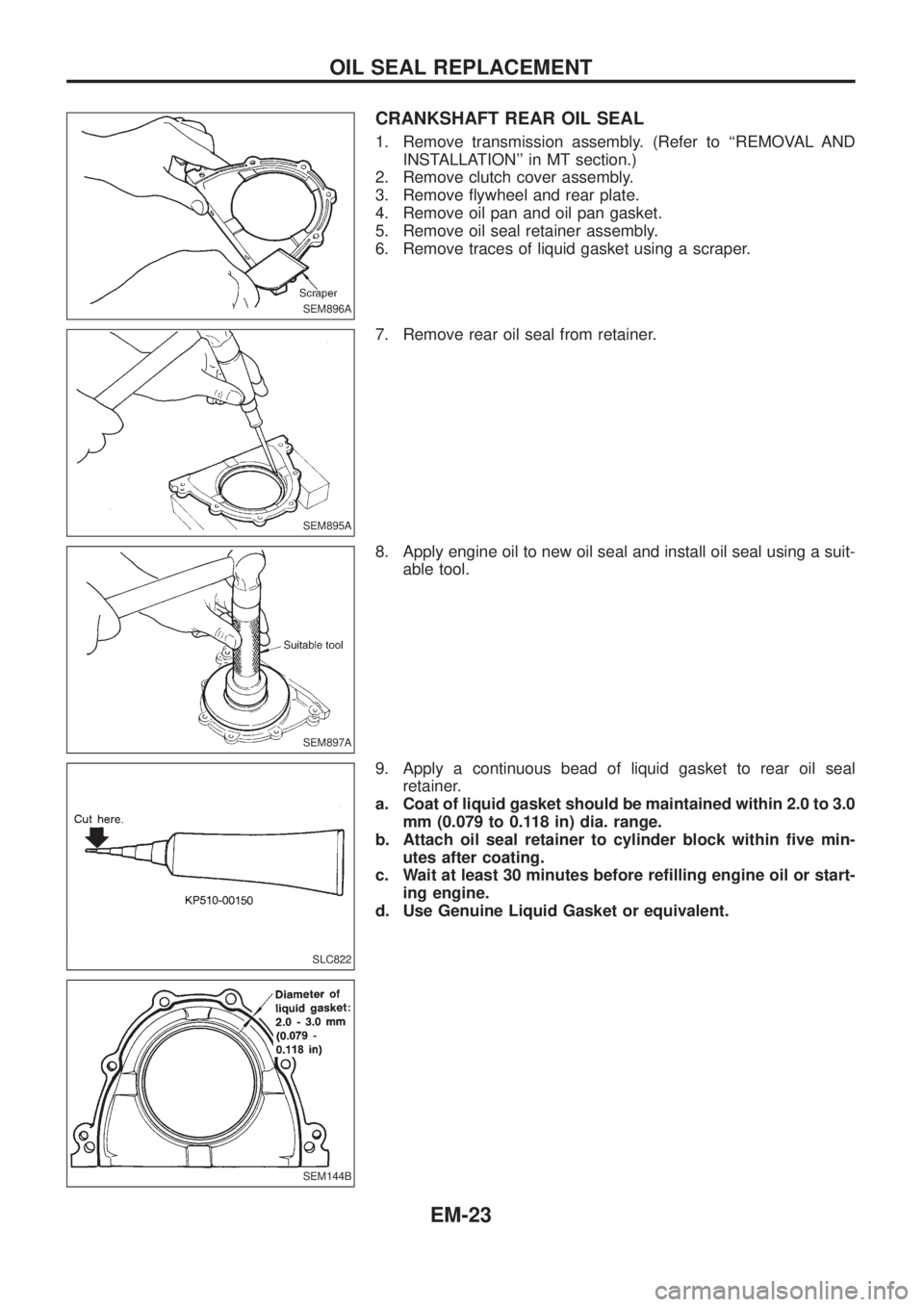
CRANKSHAFT REAR OIL SEAL
1. Remove transmission assembly. (Refer to ``REMOVAL AND
INSTALLATION'' in MT section.)
2. Remove clutch cover assembly.
3. Remove ¯ywheel and rear plate.
4. Remove oil pan and oil pan gasket.
5. Remove oil seal retainer assembly.
6. Remove traces of liquid gasket using a scraper.
7. Remove rear oil seal from retainer.
8. Apply engine oil to new oil seal and install oil seal using a suit-
able tool.
9. Apply a continuous bead of liquid gasket to rear oil seal
retainer.
a. Coat of liquid gasket should be maintained within 2.0 to 3.0
mm (0.079 to 0.118 in) dia. range.
b. Attach oil seal retainer to cylinder block within ®ve min-
utes after coating.
c. Wait at least 30 minutes before re®lling engine oil or start-
ing engine.
d. Use Genuine Liquid Gasket or equivalent.
SEM896A
SEM895A
SEM897A
SLC822
SEM144B
OIL SEAL REPLACEMENT
EM-23
Page 713 of 1226
Removal
1. Remove engine, transmission and transfer's undercovers, oil
pan guard and hood.
2. Drain engine coolant.
3. Remove charge air cooler assembly.
4. Remove vacuum hoses, fuel tubes, harnesses, and connectors
and so on.
5. Remove radiator assembly.
6. Remove drive belts.
7. Remove power steering oil pump, alternator and air conditioner
compressor.
8. Remove starter motor assembly.
9. Remove front exhaust tube.
10. Remove transmission from vehicle.
Refer to MT section.
11. Hoist engine with engine slingers and remove engine mounting
bolts from both sides.
12. Remove engine from vehicle.
Installation
+Install in reverse order of removal.
ENGINE REMOVAL
EM-45
Page 776 of 1226
+Clean all disassembled parts in the designated liquid or solvent
prior to inspection or assembly.
+Replace oil seals, gaskets, packings, O-rings, locking washers,
cotter pins, self-locking nuts, etc. with new ones.
+Replace inner and outer races of tapered roller bearings and
needle bearings as a set.
+Arrange the disassembled parts in accordance with their
assembled locations and sequence.
+Do not touch the terminals of electrical components which use
microcomputers (such as ECMs).
Static electricity may damage internal electronic components.
+After disconnecting vacuum or air hoses, attach a tag to indi-
cate the proper connection.
+Use only the ¯uids and lubricants speci®ed in this manual.
+Use approved bonding agent, sealants or their equivalents
when required.
+Use tools and recommended special tools where speci®ed for
safe and efficient service repairs.
+When repairing the fuel, oil, water, vacuum or exhaust systems,
check all affected lines for leaks.
+Dispose of drained oil or the solvent used for cleaning parts in
an appropriate manner.
WARNING:
To prevent ECM from storing the diagnostic trouble codes, do
not carelessly disconnect the harness connectors which are
related to the ECCS system and TCM (Transmission Control
Module) system. The connectors should be disconnected only
when working according to the WORK FLOW of TROUBLE
DIAGNOSES in EC and AT sections.
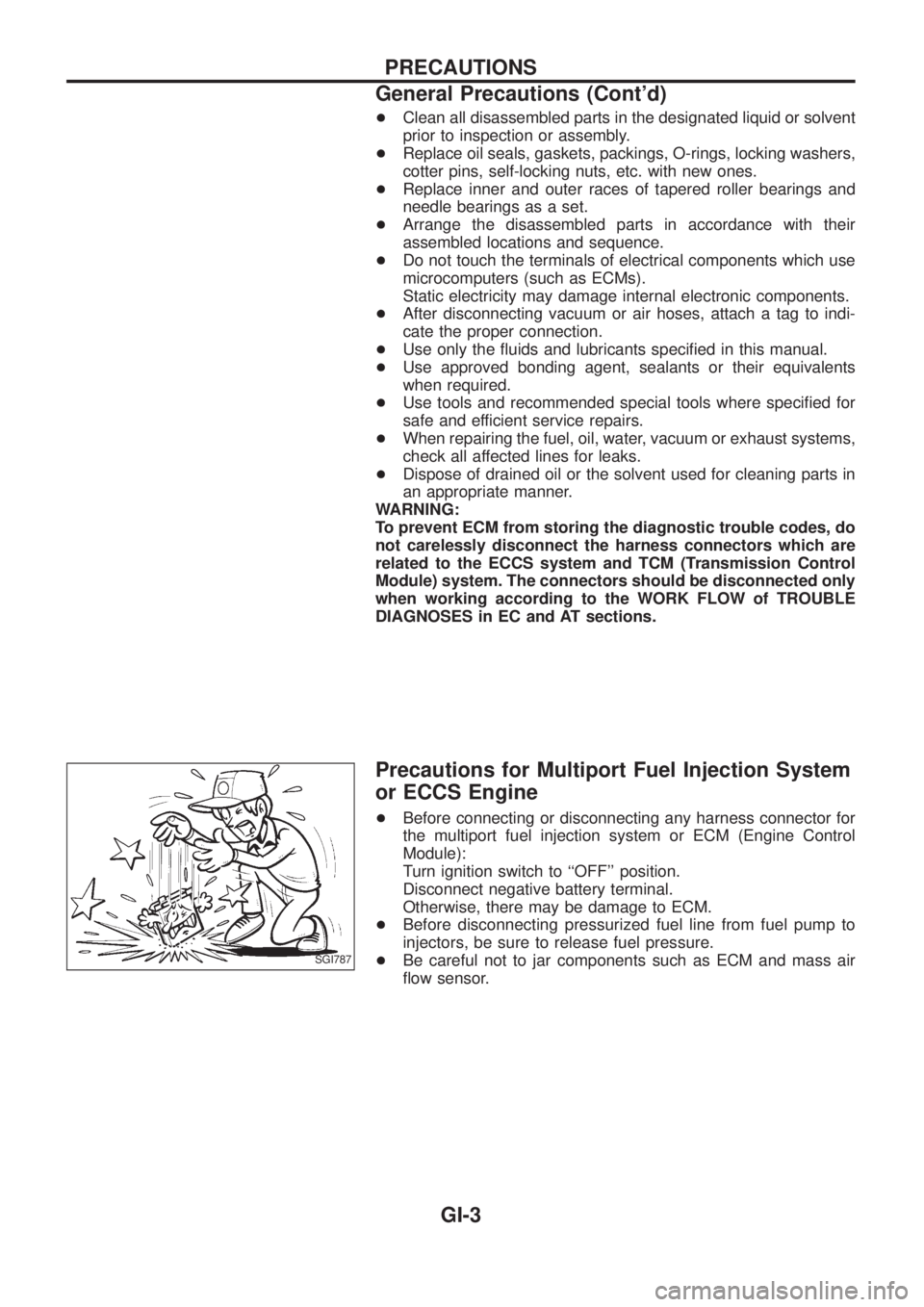
Precautions for Multiport Fuel Injection System
or ECCS Engine
+Before connecting or disconnecting any harness connector for
the multiport fuel injection system or ECM (Engine Control
Module):
Turn ignition switch to ``OFF'' position.
Disconnect negative battery terminal.
Otherwise, there may be damage to ECM.
+
Before disconnecting pressurized fuel line from fuel pump to
injectors, be sure to release fuel pressure.
+Be careful not to jar components such as ECM and mass air
¯ow sensor.SGI787
PRECAUTIONS
General Precautions (Cont'd)
GI-3
Page 780 of 1226
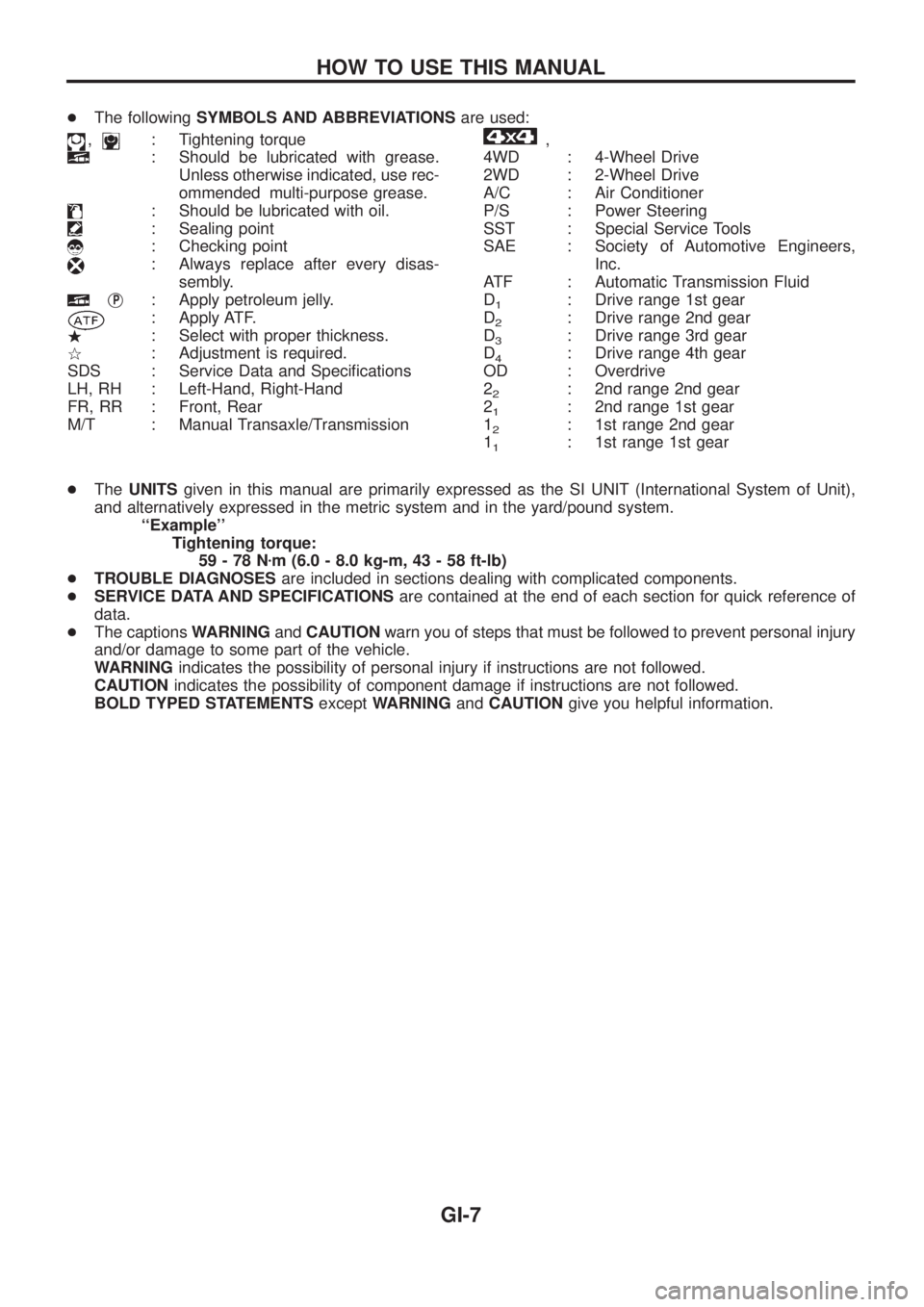
+The followingSYMBOLS AND ABBREVIATIONSare used:
,: Tightening torque
: Should be lubricated with grease.
Unless otherwise indicated, use rec-
ommended multi-purpose grease.
: Should be lubricated with oil.
: Sealing point
: Checking point
: Always replace after every disas-
sembly.
jP: Apply petroleum jelly.
: Apply ATF.
.: Select with proper thickness.
>: Adjustment is required.
SDS : Service Data and Speci®cations
LH, RH : Left-Hand, Right-Hand
FR, RR : Front, Rear
M/T : Manual Transaxle/Transmission
,
4WD : 4-Wheel Drive
2WD : 2-Wheel Drive
A/C : Air Conditioner
P/S : Power Steering
SST : Special Service Tools
SAE : Society of Automotive Engineers,
Inc.
ATF : Automatic Transmission Fluid
D
1: Drive range 1st gear
D
2: Drive range 2nd gear
D
3: Drive range 3rd gear
D
4: Drive range 4th gear
OD : Overdrive
2
2: 2nd range 2nd gear
2
1: 2nd range 1st gear
1
2: 1st range 2nd gear
1
1: 1st range 1st gear
+TheUNITSgiven in this manual are primarily expressed as the SI UNIT (International System of Unit),
and alternatively expressed in the metric system and in the yard/pound system.
``Example''
Tightening torque:
59-78Nzm (6.0 - 8.0 kg-m, 43 - 58 ft-lb)
+TROUBLE DIAGNOSESare included in sections dealing with complicated components.
+SERVICE DATA AND SPECIFICATIONSare contained at the end of each section for quick reference of
data.
+The captionsWARNINGandCAUTIONwarn you of steps that must be followed to prevent personal injury
and/or damage to some part of the vehicle.
WARNINGindicates the possibility of personal injury if instructions are not followed.
CAUTIONindicates the possibility of component damage if instructions are not followed.
BOLD TYPED STATEMENTSexceptWARNINGandCAUTIONgive you helpful information.
HOW TO USE THIS MANUAL
GI-7
Page 952 of 1226
M
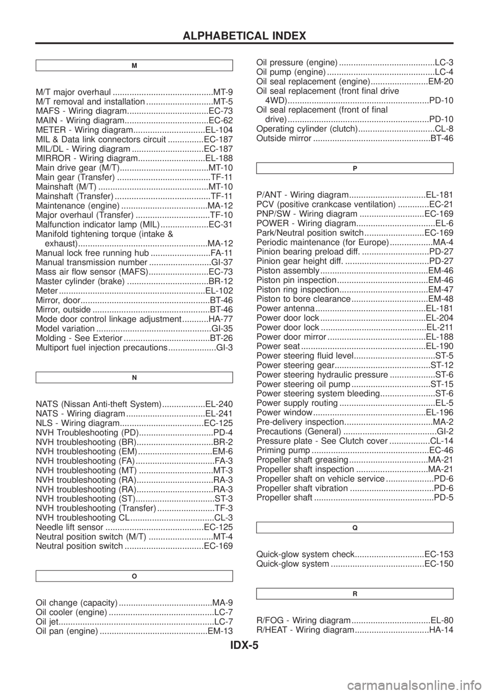
M/T major overhaul ..........................................MT-9
M/T removal and installation ............................MT-5
MAFS - Wiring diagram..................................EC-73
MAIN - Wiring diagram...................................EC-62
METER - Wiring diagram..............................EL-104
MIL & Data link connectors circuit ...............EC-187
MIL/DL - Wiring diagram ..............................EC-187
MIRROR - Wiring diagram............................EL-188
Main drive gear (M/T).....................................MT-10
Main gear (Transfer) .......................................TF-11
Mainshaft (M/T) ..............................................MT-10
Mainshaft (Transfer) ........................................TF-11
Maintenance (engine) ....................................MA-12
Major overhaul (Transfer) ...............................TF-10
Malfunction indicator lamp (MIL) ....................EC-31
Manifold tightening torque (intake &
exhaust)......................................................MA-12
Manual lock free running hub .........................FA-11
Manual transmission number ..........................GI-37
Mass air ¯ow sensor (MAFS).........................EC-73
Master cylinder (brake) ..................................BR-12
Meter .............................................................EL-102
Mirror, door......................................................BT-46
Mirror, outside .................................................BT-46
Mode door control linkage adjustment ...........HA-77
Model variation ................................................GI-35
Molding - See Exterior ....................................BT-26
Multiport fuel injection precautions ....................GI-3
N
NATS (Nissan Anti-theft System)..................EL-240
NATS - Wiring diagram .................................EL-241
NLS - Wiring diagram...................................EC-125
NVH Troubleshooting (PD)...............................PD-4
NVH troubleshooting (BR)................................BR-2
NVH troubleshooting (EM) ...............................EM-6
NVH troubleshooting (FA) .................................FA-3
NVH troubleshooting (MT) ...............................MT-3
NVH troubleshooting (RA)................................RA-3
NVH troubleshooting (RA)................................RA-3
NVH troubleshooting (ST).................................ST-3
NVH troubleshooting (Transfer) ........................TF-3
NVH troubleshooting CL ...................................CL-3
Needle lift sensor .........................................EC-125
Neutral position switch (M/T) ...........................MT-4
Neutral position switch .................................EC-169
O
Oil change (capacity) .......................................MA-9
Oil cooler (engine) ............................................LC-7
Oil jet.................................................................LC-7
Oil pan (engine) .............................................EM-13Oil pressure (engine) ........................................LC-3
Oil pump (engine) .............................................LC-4
Oil seal replacement (engine)........................EM-20
Oil seal replacement (front ®nal drive
4WD)...........................................................PD-10
Oil seal replacement (front of ®nal
drive) ...........................................................PD-10
Operating cylinder (clutch)................................CL-8
Outside mirror .................................................BT-46
P
P/ANT - Wiring diagram................................EL-181
PCV (positive crankcase ventilation) .............EC-21
PNP/SW - Wiring diagram ...........................EC-169
POWER - Wiring diagram.................................EL-6
Park/Neutral position switch .........................EC-169
Periodic maintenance (for Europe) ..................MA-4
Pinion bearing preload diff. ............................PD-27
Pinion gear height diff. ...................................PD-27
Piston assembly .............................................EM-46
Piston pin inspection ......................................EM-46
Piston ring inspection.....................................EM-47
Piston to bore clearance ................................EM-48
Power antenna ..............................................EL-181
Power door lock ............................................EL-204
Power door lock ............................................EL-211
Power door mirror .........................................EL-188
Power seat ....................................................EL-190
Power steering ¯uid level..................................ST-5
Power steering gear........................................ST-12
Power steering hydraulic pressure ...................ST-6
Power steering oil pump .................................ST-15
Power steering system bleeding.......................ST-6
Power supply routing ........................................EL-5
Power window ...............................................EL-196
Pre-delivery inspection.....................................MA-2
Precautions (General) .......................................GI-2
Pressure plate - See Clutch cover .................CL-14
Priming pump .................................................EC-46
Propeller shaft greasing .................................MA-21
Propeller shaft inspection ..............................MA-21
Propeller shaft on vehicle service ....................PD-6
Propeller shaft vibration ...................................PD-6
Propeller shaft ..................................................PD-5
Q
Quick-glow system check.............................EC-153
Quick-glow system .......................................EC-150
R
R/FOG - Wiring diagram .................................EL-80
R/HEAT - Wiring diagram ...............................HA-14
ALPHABETICAL INDEX
IDX-5
Page 979 of 1226
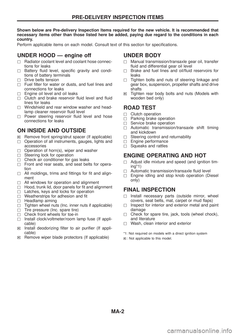
Shown below are Pre-delivery Inspection Items required for the new vehicle. It is recommended that
necessary items other than those listed here be added, paying due regard to the conditions in each
country.
Perform applicable items on each model. Consult text of this section for speci®cations.
UNDER HOOD Ð engine off
hRadiator coolant level and coolant hose connec-
tions for leaks
hBattery ¯uid level, speci®c gravity and condi-
tions of battery terminals
hDrive belts tension
hFuel ®lter for water or dusts, and fuel lines and
connections for leaks
hEngine oil level and oil leaks
hClutch and brake reservoir ¯uid level and ¯uid
lines for leaks
hWindshield and rear window washer and head-
lamp cleaner reservoir ¯uid level
hPower steering reservoir ¯uid level and hose
connections for leaks
ON INSIDE AND OUTSIDE
hXRemove front spring/strut spacer (If applicable)
hOperation of all instruments, gauges, lights and
accessories
hOperation of horn(s), wiper and washer
hSteering lock for operation
hCheck air conditioner for gas leaks
hFront and rear seats, and seat belts for opera-
tion
hAll moldings, trims and ®ttings for ®t and align-
ment
hAll windows for operation and alignment
hHood, trunk lid, door panels for ®t and alignment
hLatches, keys and locks for operation
hWeatherstrips for adhesion and ®t
hHeadlamp aiming
hTighten wheel nuts (Inc. inner nuts if applicable)
hTire pressure (Inc. spare tire)
hCheck front wheels for toe-in
hInstall clock/voltmeter/room lamp fuse (If appli-
cable)
h
XInstall deodorizing ®lter to air puri®er (If appli-
cable)
h
XRemove wiper blade protectors (If applicable)
UNDER BODY
hManual transmission/transaxle gear oil, transfer
¯uid and differential gear oil level
hBrake and fuel lines and oil/¯uid reservoirs for
leaks
hTighten bolts and nuts of steering linkage and
gear box, suspension, propeller shafts and drive
shafts
h
XTighten rear body bolts and nuts (Models with
wooden bed only)
ROAD TEST
hClutch operation
hParking brake operation
hService brake operation
hAutomatic transmission/transaxle shift timing
and kickdown
hSteering control and returnability
hEngine performance
hSqueaks and rattles
ENGINE OPERATING AND HOT
hAdjust idle mixture and speed (and ignition tim-
ing*1)
hAutomatic transmission/transaxle ¯uid level
hEngine idling and stop knob operation (Diesel
only)
FINAL INSPECTION
hInstall necessary parts (outside mirror, wheel
covers, seat belts, mat, carpet or mud ¯aps)
hInspect for interior and exterior metal and paint
damage
hCheck for spare tire, jack, tools (wheel chock),
and literature
hWash, clean interior and exterior
*1: Not required on models with a direct ignition system
h
X: Not applicable to this model.
PRE-DELIVERY INSPECTION ITEMS
MA-2
Page 983 of 1226
![NISSAN PATROL 2006 Service Manual Chassis and Body Services
Annual driving distance below 30,000 km (18,000 miles)
Abbreviations: R = Replace, I = Inspect, and correct or replace as necessary, L = Lubricate,T=Tighten.
[ ]: At the spec NISSAN PATROL 2006 Service Manual Chassis and Body Services
Annual driving distance below 30,000 km (18,000 miles)
Abbreviations: R = Replace, I = Inspect, and correct or replace as necessary, L = Lubricate,T=Tighten.
[ ]: At the spec](/img/5/57368/w960_57368-982.png)
Chassis and Body Services
Annual driving distance below 30,000 km (18,000 miles)
Abbreviations: R = Replace, I = Inspect, and correct or replace as necessary, L = Lubricate,T=Tighten.
[ ]: At the speci®ed mileage only
MAINTENANCE OPERATIONMAINTENANCE INTERVAL
Reference
page Perform either at number of kilometers (miles) or months,
whichever comes ®rst.km x 1,000 10 20 30 40 50 60 70 80 90
(Miles x 1,000) (6) (12) (18) (24) (30) (36) (42) (48) (54)
Months 6 12 18 24 30 36 42 48 54
CHASSIS AND BODY Underhood and under vehicle
Brake & clutch ¯uid (For level & leaks).I I I I MA-23, 20
Brake ¯uid.R R MA-24
Brake booster vacuum hoses, connections & check valve I I MA-24
Power steering ¯uid & lines (For level & leaks) I I I I MA-26
Brake & clutch systemsI I I I MA-24, 20
Manual transmission oil (For leaks) I I I I MA-20
Manual transmission oil[R] MA-20
Transfer ¯uidI I R I MA-21
Limited slip differential (LSD) gear oil (For level & leaks).*1 I I R I MA-22
Steering gear & linkage, axle & suspension parts, propeller shaft & exhaust system.I I I I MA-26, 20 *2
Greasing points of propeller shaftLLLLMA-21
Drive shafts & steering damper.IIII *3
Body mounting bolts & nutsTTTT *4
Outside and Inside
Wheel alignment (If necessary, rotate & balance wheels) I I I I MA-25, *5
Brake pads, discs & other brake components.I I I I MA-24
Front wheel bearing grease I R I R MA-22
Axle joint in knuckle ¯angeL L MA-23
Free running hub greaseI I I I MA-23
Headlamp aimingIIII *6
Foot brake, parking brake & clutch (For free play, stroke & operation) I I I I *7
Ventilation air ®lterRRR*8
Body corrosionAnnually MA-28
Air bag systemSee NOTE (1) *9
NOTE: (1) Inspect after 10 years, then every 2 years.
(2) Maintenance items with ``.'' should be performed more frequently according to ``Maintenance Under Severe Driv-
ing Conditions''.
*1: Including differential gear with differential lock
*2: ``Front Axle and Front Suspension Parts'' in FA section, ``Rear Axle and Rear Suspension Parts'' in RA section
*3: ``FRONT AXLE Ð Drive Shaft'' in FA section
*4: ``CAB BODY'' in BT section
*5: ``Front Wheel Alignment'' in FA section
*6: ``Aiming Adjustment'' in EL section
*7: ``Brake Pedal and Bracket'' in BR section, ``Adjusting Clutch Pedal'' in CL section
*8: ``Ventilation air ®lter'' in HA section
*9: ``Maintenance Items'' in RS section
PERIODIC MAINTENANCE
MA-6
Page 984 of 1226
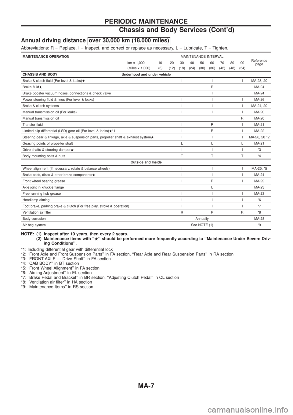
Annual driving distance over 30,000 km (18,000 miles)
Abbreviations: R = Replace. I = Inspect, and correct or replace as necessary, L = Lubricate,T=Tighten.
MAINTENANCE OPERATIONMAINTENANCE INTERVAL
Reference
page km x 1,000 10 20 30 40 50 60 70 80 90
(Miles x 1,000) (6) (12) (18) (24) (30) (36) (42) (48) (54)
CHASSIS AND BODY Underhood and under vehicle
Brake & clutch ¯uid (For level & leaks).I I I MA-23, 20
Brake ¯uid.R MA-24
Brake booster vacuum hoses, connections & check valve I MA-24
Power steering ¯uid & lines (For level & leaks) I I I MA-26
Brake & clutch systemsI I I MA-24, 20
Manual transmission oil (For leaks) I I I MA-20
Manual transmission oilR MA-20
Transfer ¯uidI R I MA-21
Limited slip differential (LSD) gear oil (For level & leaks).*1 I R I MA-22
Steering gear & linkage, axle & suspension parts, propeller shaft & exhaust system.I I I MA-26, 20 *2
Geasing points of propeller shaft L L L MA-21
Drive shafts & steering damper.III*3
Body mounting bolts & nutsTTT*4
Outside and Inside
Wheel alignment (If necessary, rotate & balance wheels) I I I MA-25, *5
Brake pads, discs & other brake components.I I I MA-24
Front wheel bearing greaseI R I MA-22
Axle joint in knuckle ¯angeL MA-23
Free running hub greaseI I I MA-23
Headlamp aimingIII*6
Foot brake, parking brake & clutch (For free play, stroke & operation) I I I *7
Ventilation air ®lterRRR*8
Body corrosionAnnually MA-28
Air bag systemSee NOTE (1) *9
NOTE: (1) Inspect after 10 years, then every 2 years.
(2) Maintenance items with ``.'' should be performed more frequently according to ``Maintenance Under Severe Driv-
ing Conditions''.
*1: Including differential gear with differential lock
*2: ``Front Axle and Front Suspension Parts'' in FA section, ``Rear Axle and Rear Suspension Parts'' in RA section
*3: ``FRONT AXLE Ð Drive Shaft'' in FA section
*4: ``CAB BODY'' in BT section
*5: ``Front Wheel Alignment'' in FA section
*6: ``Aiming Adjustment'' in EL section
*7: ``Brake Pedal and Bracket'' in BR section, ``Adjusting Clutch Pedal'' in CL section
*8: ``Ventilation air ®lter'' in HA section
*9: ``Maintenance Items'' in RS section
PERIODIC MAINTENANCE
Chassis and Body Services (Cont'd)
MA-7
Page 985 of 1226
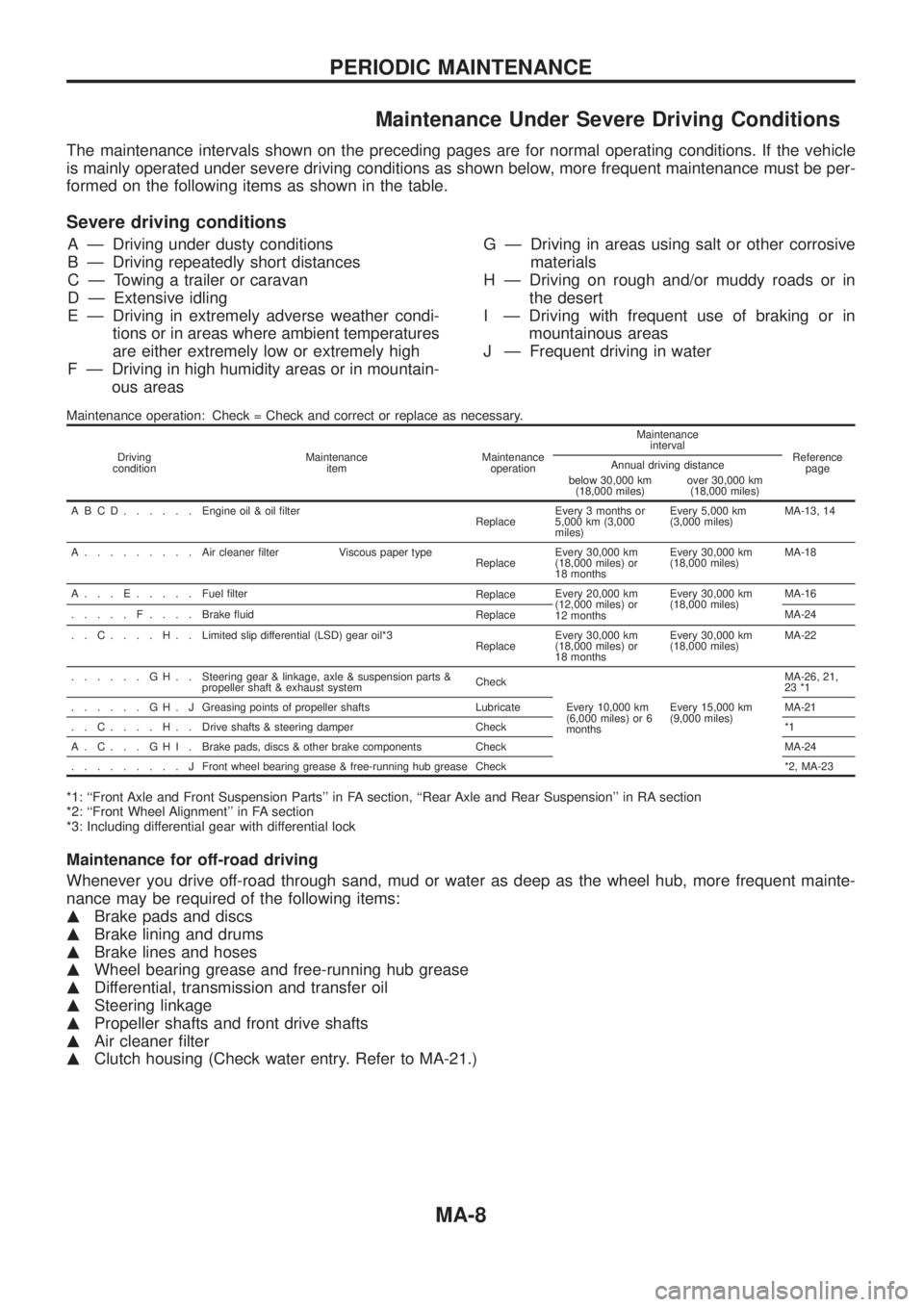
Maintenance Under Severe Driving Conditions
The maintenance intervals shown on the preceding pages are for normal operating conditions. If the vehicle
is mainly operated under severe driving conditions as shown below, more frequent maintenance must be per-
formed on the following items as shown in the table.
Severe driving conditions
A Ð Driving under dusty conditions
B Ð Driving repeatedly short distances
C Ð Towing a trailer or caravan
D Ð Extensive idling
E Ð Driving in extremely adverse weather condi-
tions or in areas where ambient temperatures
are either extremely low or extremely high
F Ð Driving in high humidity areas or in mountain-
ous areasG Ð Driving in areas using salt or other corrosive
materials
H Ð Driving on rough and/or muddy roads or in
the desert
I Ð Driving with frequent use of braking or in
mountainous areas
J Ð Frequent driving in water
Maintenance operation: Check = Check and correct or replace as necessary.
Driving
conditionMaintenance
itemMaintenance
operationMaintenance
interval
Reference
page Annual driving distance
below 30,000 km
(18,000 miles)over 30,000 km
(18,000 miles)
ABCD......Engine oil & oil ®lter
ReplaceEvery 3 months or
5,000 km (3,000
miles)Every 5,000 km
(3,000 miles)MA-13, 14
A.........Aircleaner ®lter Viscous paper type
ReplaceEvery 30,000 km
(18,000 miles) or
18 monthsEvery 30,000 km
(18,000 miles)MA-18
A...E.....Fuel ®lter
ReplaceEvery 20,000 km
(12,000 miles) or
12 monthsEvery 30,000 km
(18,000 miles)MA-16
.....F....Brake ¯uid
ReplaceMA-24
..C....H..Limited slip differential (LSD) gear oil*3
ReplaceEvery 30,000 km
(18,000 miles) or
18 monthsEvery 30,000 km
(18,000 miles)MA-22
......GH..Steering gear & linkage, axle & suspension parts &
propeller shaft & exhaust systemCheck
Every 10,000 km
(6,000 miles) or 6
monthsEvery 15,000 km
(9,000 miles)MA-26, 21,
23 *1
......GH.JGreasing points of propeller shafts Lubricate MA-21
..C....H..Drive shafts & steering damper Check *1
A.C...GHI.Brake pads, discs & other brake components Check MA-24
.........JFront wheel bearing grease & free-running hub grease Check *2, MA-23
*1: ``Front Axle and Front Suspension Parts'' in FA section, ``Rear Axle and Rear Suspension'' in RA section
*2: ``Front Wheel Alignment'' in FA section
*3: Including differential gear with differential lock
Maintenance for off-road driving
Whenever you drive off-road through sand, mud or water as deep as the wheel hub, more frequent mainte-
nance may be required of the following items:
mBrake pads and discs
mBrake lining and drums
mBrake lines and hoses
mWheel bearing grease and free-running hub grease
mDifferential, transmission and transfer oil
mSteering linkage
mPropeller shafts and front drive shafts
mAir cleaner ®lter
mClutch housing (Check water entry. Refer to MA-21.)
PERIODIC MAINTENANCE
MA-8
Page 986 of 1226
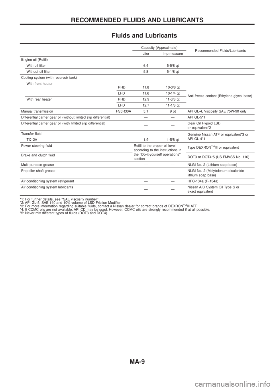
Fluids and Lubricants
Capacity (Approximate)Recommended Fluids/Lubricants
Liter Imp measure
Engine oil (Re®ll) With oil ®lter 6.4 5-5/8 qt
Without oil ®lter 5.8 5-1/8 qt
Cooling system (with reservoir tank)
Anti-freeze coolant (Ethylene glycol base)
With front heater
RHD 11.8 10-3/8 qt
LHD 11.6 10-1/4 qt
With rear heater RHD 12.9 11-3/8 qt LHD 12.7 11-1/8 qt
Manual transmission FS5R30A 5.1 9 pt API GL-4, Viscosity SAE 75W-90 only
Differential carrier gear oil (without limited slip differential) Ð Ð API GL-5*1
Differential carrier gear oil (with limited slip differential) ÐÐGearOilHypoidLSD
orequivalent*2
Transfer ¯uid Genuine Nissan ATF or equivalent*3 or
API GL-4*1
TX12A 1.9 1-5/8 qt
Power steering ¯uid Re®ll to the proper oil level according to the instructions in
the ``Do-it-yourself operations''
sectionType DEXRON
TMIII or equivalent
Brake and clutch ¯uid DOT3 or DOT4*5 (US FMVSS No. 116)
Multi-purpose grease Ð Ð NLGI No. 2 (Lithium soap base)
Propeller shaft grease NLGI No. 2 (Molybdenum disulphide
lithium soap base)
Air conditioning system refrigerant Ð Ð HFC-134a (R-134a)
Air conditioning system lubricants ÐÐNissan A/C System Oil Type S or
exact equivalent
*1: For further details, see ``SAE viscosity number''.
*2:APIGL-5,SAE140and10%volumeofLSDFrictionModi®er
*3: For more information regarding suitable ¯uids, contact a Nissan dealer for correct brands of DEXRON
TMIII ATF.
*4: If CCMC oils are not available, API CD may be used. However, CCMC oils are strongly recommended if at all possible.
*5: Never mix different types of ¯uids (DOT3 and DOT4).
RECOMMENDED FLUIDS AND LUBRICANTS
MA-9