ESP NISSAN PICK-UP 1998 Service Manual
[x] Cancel search | Manufacturer: NISSAN, Model Year: 1998, Model line: PICK-UP, Model: NISSAN PICK-UP 1998Pages: 1659, PDF Size: 53.39 MB
Page 1596 of 1659
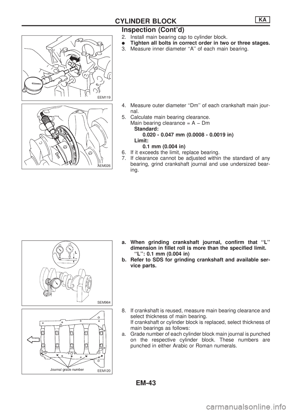
2. Install main bearing cap to cylinder block.
lTighten all bolts in correct order in two or three stages.
3. Measure inner diameter ``A'' of each main bearing.
4. Measure outer diameter ``Dm'' of each crankshaft main jour-
nal.
5. Calculate main bearing clearance.
Main bearing clearance=AþDm
Standard:
0.020 - 0.047 mm (0.0008 - 0.0019 in)
Limit:
0.1 mm (0.004 in)
6. If it exceeds the limit, replace bearing.
7. If clearance cannot be adjusted within the standard of any
bearing, grind crankshaft journal and use undersized bear-
ing.
a. When grinding crankshaft journal, confirm that ``L''
dimension in fillet roll is more than the specified limit.
``L'': 0.1 mm (0.004 in)
b. Refer to SDS for grinding crankshaft and available ser-
vice parts.
8. If crankshaft is reused, measure main bearing clearance and
select thickness of main bearing.
If crankshaft or cylinder block is replaced, select thickness of
main bearings as follows:
a. Grade number of each cylinder block main journal is punched
on the respective cylinder block. These numbers are
punched in either Arabic or Roman numerals.
EEM119
AEM026
SEM964
EEM120
CYLINDER BLOCKKA
Inspection (Cont'd)
EM-43
Page 1600 of 1659
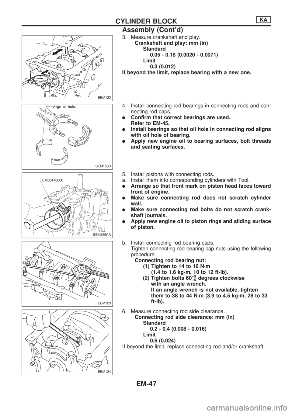
3. Measure crankshaft end play.
Crankshaft end play: mm (in)
Standard
0.05 - 0.18 (0.0020 - 0.0071)
Limit
0.3 (0.012)
If beyond the limit, replace bearing with a new one.
4. Install connecting rod bearings in connecting rods and con-
necting rod caps.
lConfirm that correct bearings are used.
Refer to EM-45.
lInstall bearings so that oil hole in connecting rod aligns
with oil hole of bearing.
lApply new engine oil to bearing surfaces, bolt threads
and seating surfaces.
5. Install pistons with connecting rods.
a. Install them into corresponding cylinders with Tool.
lArrange so that front mark on piston head faces toward
front of engine.
lMake sure connecting rod does not scratch cylinder
wall.
lMake sure connecting rod bolts do not scratch crank-
shaft journals.
lApply new engine oil to piston rings and sliding surface
of piston.
b. Install connecting rod bearing caps.
Tighten connecting rod bearing cap nuts using the following
procedure.
Connecting rod bearing nut:
(1) Tighten to 14 to 16 N´m
(1.4 to 1.6 kg-m, 10 to 12 ft-lb).
(2) Tighten bolts 60
+5
þ0degrees clockwise
with an angle wrench.
If an angle wrench is not available, tighten
them to 38 to 44 N´m (3.9 to 4.5 kg-m, 28 to 33
ft-lb).
6. Measure connecting rod side clearance.
Connecting rod side clearance: mm (in)
Standard
0.2 - 0.4 (0.008 - 0.016)
Limit
0.6 (0.024)
If beyond the limit, replace connecting rod and/or crankshaft.
EEM122
SEM159B
SEM269CA
EEM123
EEM124
CYLINDER BLOCKKA
Assembly (Cont'd)
EM-47
Page 1605 of 1659
Removal
Removal order and pointsApplied model
2WD 4WD
1 Remove undercover.jj
2 Drain engine oil.jj
3Remove front propeller shaft
from front differential carrier.Ðj
4Remove front drive shaft fix-
ing bolts (RH & LH).Ðj
5Remove front suspension
crossmember.jj
6Remove differential front
mounting bolts (RH & LH)
and rear mounting bolts.Ðj
7Remove front differential car-
rier.ÐjRemoval order and pointsApplied model
2WD 4WD
8Remove front differential car-
rier mounting bracket.Ðj
9Remove transmission to rear
engine mounting bracket
nuts (RH & LH).jj
10Remove engine mounting
bolts or nuts (RH & LH).jj
11Lift up engine.
If necessary, disconnect
exhaust tube.jj
12 Remove oil pan.jj
WARNING:
lPlace vehicle on a flat and solid surface.
lPlace chocks at front and rear of rear wheels.
lYou should not remove oil pan until exhaust system and
cooling system have completely cooled off.
Otherwise, you may burn yourself and/or fire may break
out in the fuel line.
lWhen removing front and/or rear engine mounting bolts
or nuts, lift up slightly engine for safety work.
CAUTION:
lIn lifting engine, be careful not to hit against adjacent
parts, especially against accelerator wire casing end,
brake tube and brake master cylinder.
lFor tightening torque, refer to EM-71, MT and PD sec-
tions.
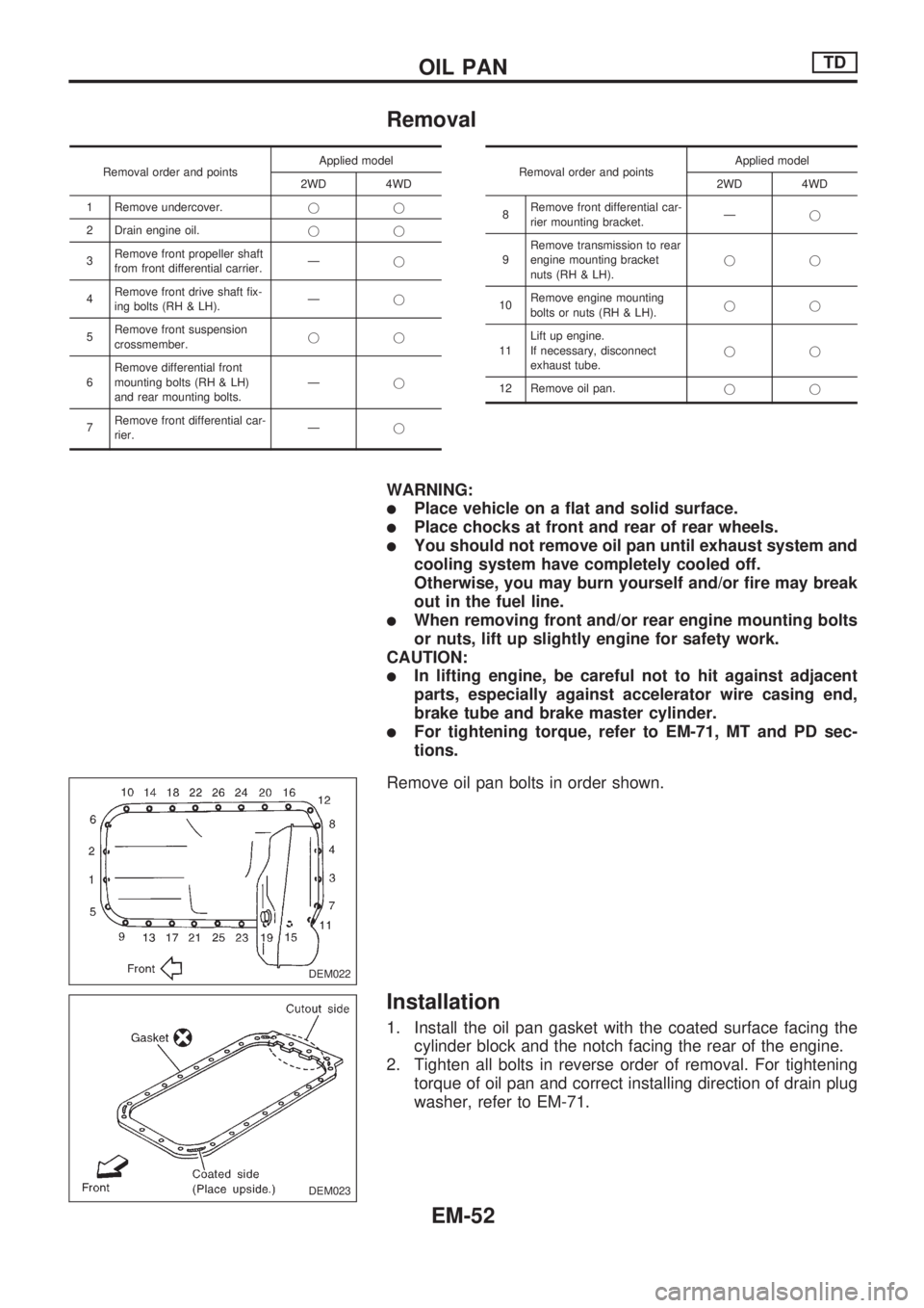
Remove oil pan bolts in order shown.
Installation
1. Install the oil pan gasket with the coated surface facing the
cylinder block and the notch facing the rear of the engine.
2. Tighten all bolts in reverse order of removal. For tightening
torque of oil pan and correct installing direction of drain plug
washer, refer to EM-71.
DEM022
DEM023
OIL PANTD
EM-52
Page 1639 of 1659
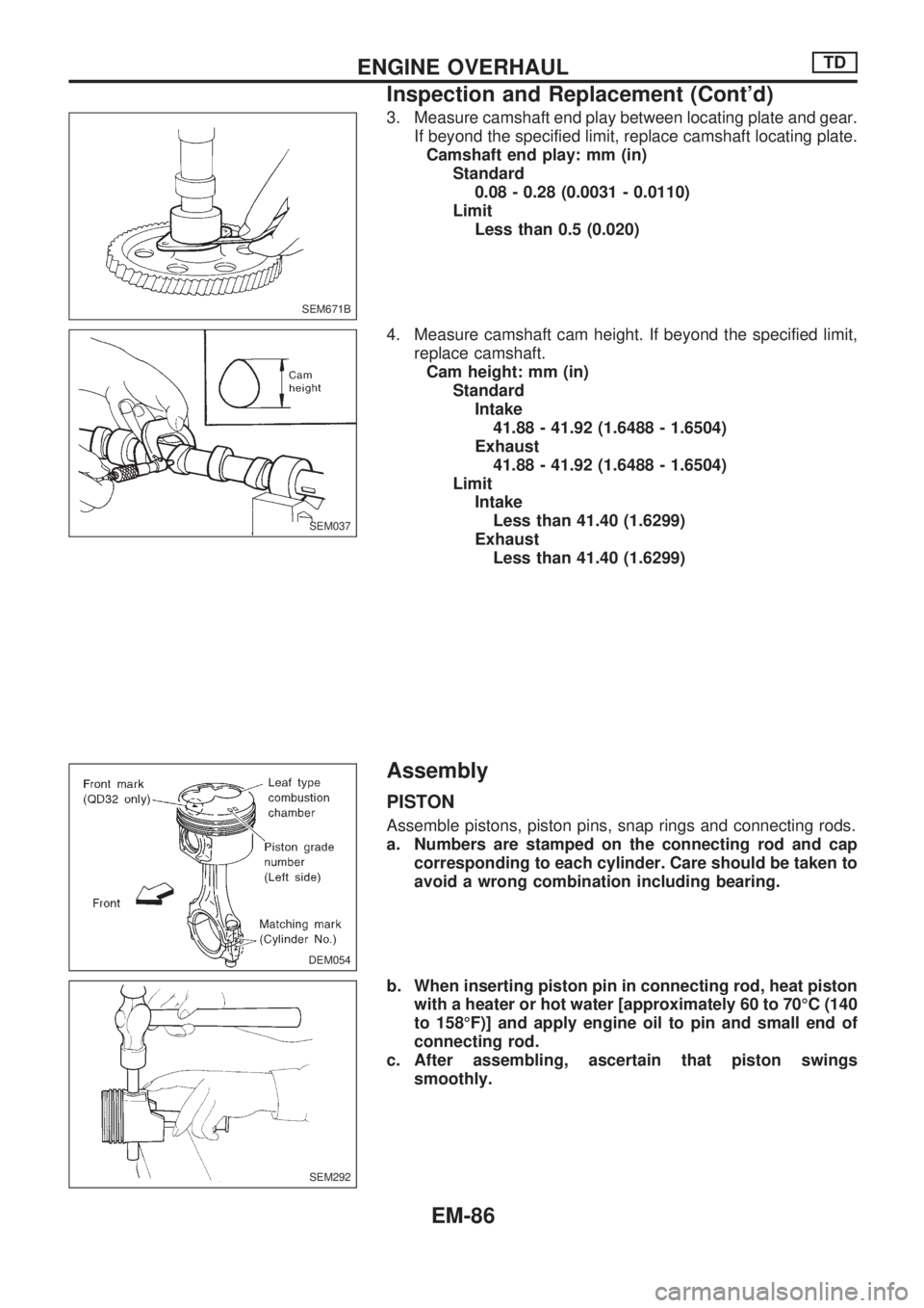
3. Measure camshaft end play between locating plate and gear.
If beyond the specified limit, replace camshaft locating plate.
Camshaft end play: mm (in)
Standard
0.08 - 0.28 (0.0031 - 0.0110)
Limit
Less than 0.5 (0.020)
4. Measure camshaft cam height. If beyond the specified limit,
replace camshaft.
Cam height: mm (in)
Standard
Intake
41.88 - 41.92 (1.6488 - 1.6504)
Exhaust
41.88 - 41.92 (1.6488 - 1.6504)
Limit
Intake
Less than 41.40 (1.6299)
Exhaust
Less than 41.40 (1.6299)
Assembly
PISTON
Assemble pistons, piston pins, snap rings and connecting rods.
a. Numbers are stamped on the connecting rod and cap
corresponding to each cylinder. Care should be taken to
avoid a wrong combination including bearing.
b. When inserting piston pin in connecting rod, heat piston
with a heater or hot water [approximately 60 to 70ÉC (140
to 158ÉF)] and apply engine oil to pin and small end of
connecting rod.
c. After assembling, ascertain that piston swings
smoothly.
SEM671B
SEM037
DEM054
SEM292
ENGINE OVERHAULTD
Inspection and Replacement (Cont'd)
EM-86
Page 1641 of 1659
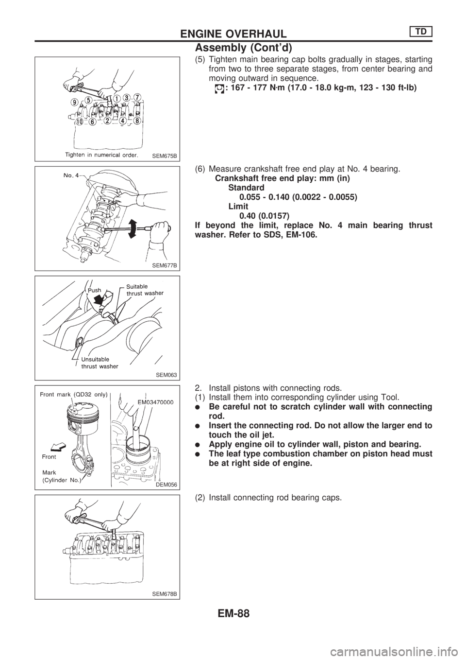
(5) Tighten main bearing cap bolts gradually in stages, starting
from two to three separate stages, from center bearing and
moving outward in sequence.
: 167 - 177 Nzm (17.0 - 18.0 kg-m, 123 - 130 ft-lb)
(6) Measure crankshaft free end play at No. 4 bearing.
Crankshaft free end play: mm (in)
Standard
0.055 - 0.140 (0.0022 - 0.0055)
Limit
0.40 (0.0157)
If beyond the limit, replace No. 4 main bearing thrust
washer. Refer to SDS, EM-106.
2. Install pistons with connecting rods.
(1) Install them into corresponding cylinder using Tool.
lBe careful not to scratch cylinder wall with connecting
rod.
lInsert the connecting rod. Do not allow the larger end to
touch the oil jet.
lApply engine oil to cylinder wall, piston and bearing.
lThe leaf type combustion chamber on piston head must
be at right side of engine.
(2) Install connecting rod bearing caps.
SEM675B
SEM677B
SEM063
DEM056.DEM056
SEM678B
ENGINE OVERHAULTD
Assembly (Cont'd)
EM-88