door lock NISSAN PICK-UP 1998 Repair Manual
[x] Cancel search | Manufacturer: NISSAN, Model Year: 1998, Model line: PICK-UP, Model: NISSAN PICK-UP 1998Pages: 1659, PDF Size: 53.39 MB
Page 110 of 1659
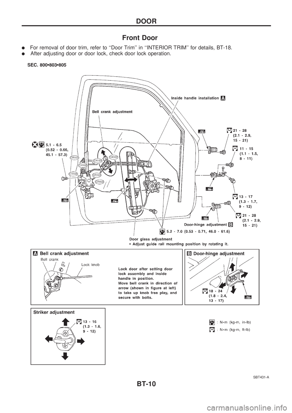
Front Door
lFor removal of door trim, refer to ``Door Trim'' in ``INTERIOR TRIM'' for details, BT-18.
lAfter adjusting door or door lock, check door lock operation.
SBT431-A
DOOR
BT-10
Page 389 of 1659
HEADLAMP - Headlamp Aiming Control -........... 63
System Description .............................................. 63
Wiring Diagram - H/AIM - .................................... 64
PARKING, LICENSE AND TAIL LAMPS............... 66
Wiring Diagram - TAIL/L -/Except for LHD
Models for Europe ............................................... 66
Wiring Diagram - TAIL/L -/LHD Models for
Europe.................................................................. 68
STOP LAMP............................................................ 70
Wiring Diagram - STOP/L - ................................. 70
BACK-UP LAMP...................................................... 71
Wiring Diagram - BACK/L - ................................. 71
REAR FOG LAMP................................................... 72
Wiring Diagram - R/FOG -/LHD Models .............. 72
Wiring Diagram - R/FOG -/RHD Models ............. 73
TURN SIGNAL AND HAZARD WARNING
LAMPS..................................................................... 74
Schematic ............................................................ 74
Wiring Diagram - TURN -/Except 4WD Models
for Europe ............................................................ 75
Wiring Diagram - TURN -/4WD Models for
Europe.................................................................. 77
Trouble Diagnoses ............................................... 80
Combination Flasher Unit Check ......................... 80
ILLUMINATION........................................................ 81
Wiring Diagram - ILL -/LHD Models .................... 81
Wiring Diagram - ILL -/RHD Models.................... 83
INTERIOR AND SPOT LAMPS............................... 85
Wiring Diagram - INT/L - ..................................... 85
Combination Meter............................................... 87
Schematic ............................................................ 89
Wiring Diagram - METER -/LHD Models............. 90
Wiring Diagram - METER -/RHD Models ............ 93
Unified Control Meter System Description .......... 96
Meter/gauge Operation and Odo/Trip Meter
Segment Check in Diagnosis Mode .................... 96
Flexible Print Circuit (FPC) .................................. 97
Trouble Diagnoses ............................................... 98
Electrical Components Inspection ..................... 103
WARNING LAMPS................................................ 105
Schematic .......................................................... 105
Wiring Diagram - WARN -/LHD Models ............ 106
Wiring Diagram - WARN -/RHD Models............ 111
Electrical Components Inspection ..................... 116
WARNING BUZZER.............................................. 117
Wiring diagram - BUZZER -/LHD Models for
Europe................................................................ 117
Wiring diagram - BUZZER -/RHD Models for
Europe................................................................ 118
Electrical Components Inspection ..................... 119
FRONT WIPER AND WASHER............................ 120
System Description ............................................ 120
Wiring Diagram - WIPER -/LHD Models with
Intermittent ......................................................... 122Wiring Diagram - WIPER -/RHD Models with
Intermittent ......................................................... 124
Trouble Diagnoses ............................................. 126
Wiper Installation and Adjustment ..................... 127
Washer Nozzle Adjustment ............................... 128
Washer Tube Layout ......................................... 128
Wiper Linkage .................................................... 129
HEADLAMP WASHER.......................................... 130
Wiring Diagram - HLC - ..................................... 130
Trouble Diagnoses ............................................. 131
Washer Tube Layout ......................................... 131
Check Valve ....................................................... 131
HORN..................................................................... 132
Wiring Diagram - HORN -.................................. 132
CIGARETTE LIGHTER.......................................... 133
Wiring Diagram - CIGAR - ................................. 133
CLOCK................................................................... 134
Wiring Diagram - CLOCK - ................................ 134
REAR WINDOW DEFOGGER............................... 135
Wiring Diagram - DEF - ..................................... 135
Electrical Components Inspection ..................... 136
Filament Check .................................................. 136
Filament Repair.................................................. 137
AUDIO.................................................................... 138
Wiring Diagram - AUDIO -/LHD Models Type-
2 ......................................................................... 138
Wiring Diagram - AUDIO -/LHD Models Type-
3 ......................................................................... 139
Wiring Diagram - AUDIO -/RHD Models ........... 141
Trouble Diagnoses ............................................. 142
CATS (Code) System/For Europe RHD ............ 143
NATS Audio Link/For Europe LHD (KA24E) ..... 144
AUDIO ANTENNA................................................. 146
Manual Antenna ................................................. 146
Power Antenna/Wiring Diagram - P/ANT - ........ 147
Power Antenna .................................................. 148
POWER DOOR MIRROR...................................... 150
Wiring Diagram - MIRROR -.............................. 150
HEATED SEAT...................................................... 152
Wiring Diagram - H/SEAT - ............................... 152
POWER WINDOW................................................. 154
System Description ............................................ 154
Schematic .......................................................... 156
Wiring Diagram - WINDOW -/LHD Models ....... 157
Wiring Diagram - WINDOW -/RHD Models ....... 161
Trouble Diagnoses ............................................. 165
POWER DOOR LOCK........................................... 166
System Description ............................................ 166
Wiring Diagram - D/LOCK - ............................... 167
Trouble Diagnosis .............................................. 169
MULTI-REMOTE CONTROL SYSTEM/FOR
EUROPE................................................................ 173
System Description ............................................ 173
Schematic .......................................................... 174
Page 390 of 1659
Wiring Diagram - MULTI -/LHD Models ............ 175
Trouble Diagnoses ............................................. 179
ID Code Entry Procedure .................................. 182
NATS (Nissan Anti-Theft System)/Gasoline
engine for LHD models........................................ 183
Component Parts and Harness Connector
Location.............................................................. 183
System Description ............................................ 183
System Composition .......................................... 184
Wiring Diagram - NATS -................................... 185
CONSULT .......................................................... 186
Trouble Diagnoses ............................................. 188
How to Replace NATS IMMU ............................ 197
NATS (Nissan Anti-Theft System)/Diesel
engine.................................................................... 198
Component Parts and Harness Connector
Location.............................................................. 198
System Description ............................................ 199
System Composition .......................................... 199
Wiring Diagram - NATS -/LHD Models.............. 200
Wiring Diagram - NATS -/RHD Models ............. 201
CONSULT .......................................................... 202
Trouble Diagnoses ............................................. 205LOCATION OF ELECTRICAL UNITS................... 217
Engine Compartment ......................................... 217
Passenger Compartment ................................... 218
HARNESS LAYOUT.............................................. 220
Outline ................................................................ 220
How to Read Harness Layout ........................... 221
Main Harness ..................................................... 222
Engine Room Harness....................................... 232
Engine Control Harness..................................... 240
Engine Harness ................................................. 242
Alternator Harness ............................................. 244
Instrument Harness............................................ 245
Room Lamp Harness/LHD Models .................... 246
Room Lamp Harness/RHD Models ................... 247
Chassis Harness and Tail Harness ................... 248
Front Door Harness (LH side) ........................... 249
Front Door Harness (RH side)........................... 250
Rear Door Harness ............................................ 251
BULB SPECIFICATIONS...................................... 252
Headlamp ........................................................... 252
Exterior Lamp..................................................... 252
Interior Lamp ...................................................... 252
WIRING DIAGRAM CODES (CELL CODES)....... 253
WIRING DIAGRAM REFERENCE CHART
COOLING FAN .......................................................................................................... LC SECTION
ECCS, IGNITION SYSTEM, QUICK-GLOW SYSTEM, FUEL HEATER SYSTEM .. EC SECTION
ANTI-LOCK BRAKE SYSTEM .................................................................................. BR SECTION
SRS ``AIR BAG'' ........................................................................................................ RS SECTION
HEATER AND AIR CONDITIONER .......................................................................... HA SECTION
Page 403 of 1659
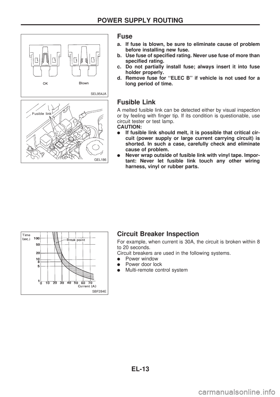
Fuse
a. If fuse is blown, be sure to eliminate cause of problem
before installing new fuse.
b. Use fuse of specified rating. Never use fuse of more than
specified rating.
c. Do not partially install fuse; always insert it into fuse
holder properly.
d. Remove fuse for ``ELEC B'' if vehicle is not used for a
long period of time.
Fusible Link
A melted fusible link can be detected either by visual inspection
or by feeling with finger tip. If its condition is questionable, use
circuit tester or test lamp.
CAUTION:
lIf fusible link should melt, it is possible that critical cir-
cuit (power supply or large current carrying circuit) is
shorted. In such a case, carefully check and eliminate
cause of problem.
lNever wrap outside of fusible link with vinyl tape. Impor-
tant: Never let fusible link touch any other wiring
harness, vinyl or rubber parts.
Circuit Breaker Inspection
For example, when current is 30A, the circuit is broken within 8
to 20 seconds.
Circuit breakers are used in the following systems.
lPower window
lPower door lock
lMulti-remote control system
SEL954JA
GEL186
SBF284E
POWER SUPPLY ROUTING
EL-13
Page 404 of 1659
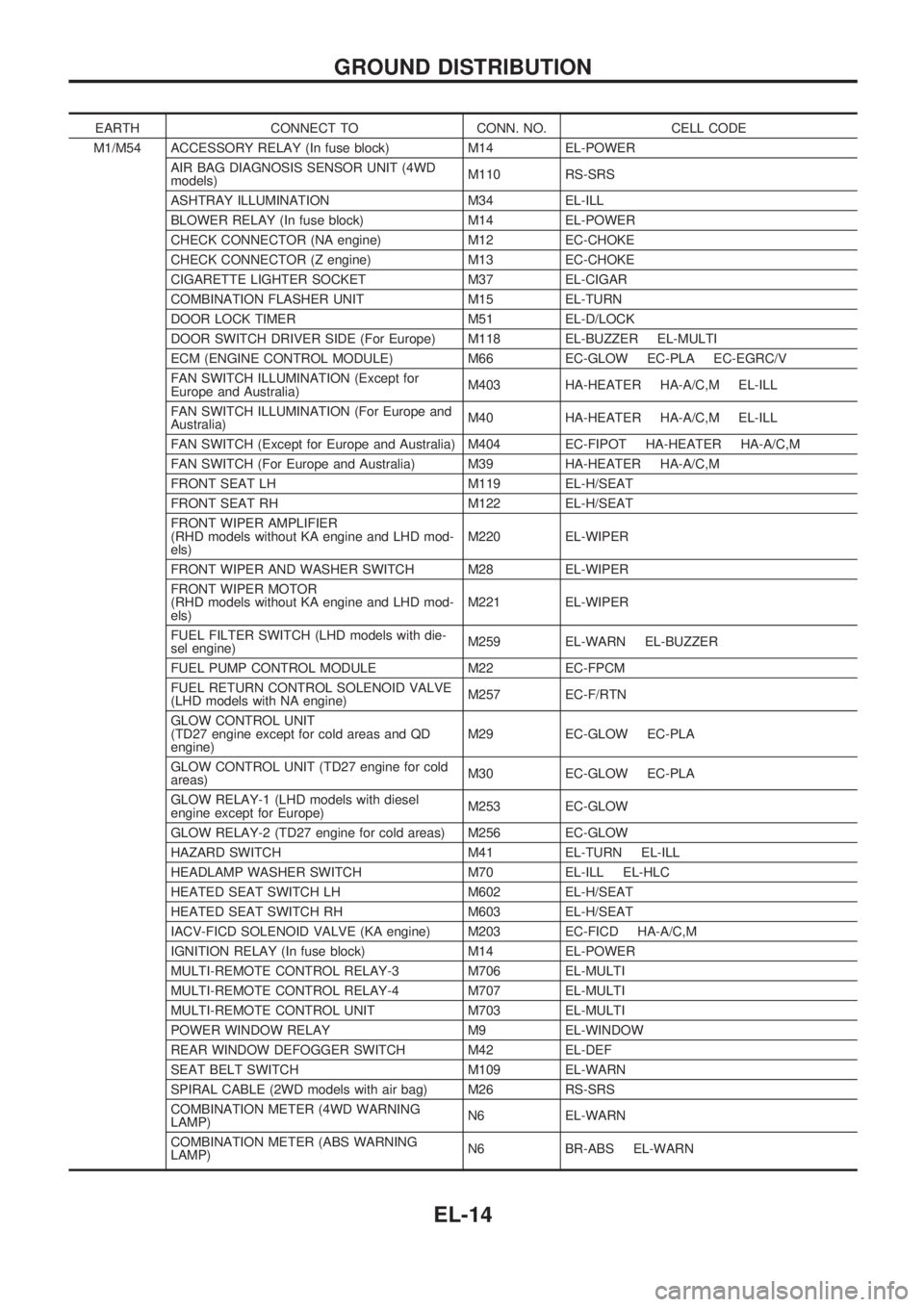
EARTH CONNECT TO CONN. NO. CELL CODE
M1/M54 ACCESSORY RELAY (In fuse block) M14 EL-POWER
AIR BAG DIAGNOSIS SENSOR UNIT (4WD
models)M110 RS-SRS
ASHTRAY ILLUMINATION M34 EL-ILL
BLOWER RELAY (In fuse block) M14 EL-POWER
CHECK CONNECTOR (NA engine) M12 EC-CHOKE
CHECK CONNECTOR (Z engine) M13 EC-CHOKE
CIGARETTE LIGHTER SOCKET M37 EL-CIGAR
COMBINATION FLASHER UNIT M15 EL-TURN
DOOR LOCK TIMER M51 EL-D/LOCK
DOOR SWITCH DRIVER SIDE (For Europe) M118 EL-BUZZER EL-MULTI
ECM (ENGINE CONTROL MODULE) M66 EC-GLOW EC-PLA EC-EGRC/V
FAN SWITCH ILLUMINATION (Except for
Europe and Australia)M403 HA-HEATER HA-A/C,M EL-ILL
FAN SWITCH ILLUMINATION (For Europe and
Australia)M40 HA-HEATER HA-A/C,M EL-ILL
FAN SWITCH (Except for Europe and Australia) M404 EC-FIPOT HA-HEATER HA-A/C,M
FAN SWITCH (For Europe and Australia) M39 HA-HEATER HA-A/C,M
FRONT SEAT LH M119 EL-H/SEAT
FRONT SEAT RH M122 EL-H/SEAT
FRONT WIPER AMPLIFIER
(RHD models without KA engine and LHD mod-
els)M220 EL-WIPER
FRONT WIPER AND WASHER SWITCH M28 EL-WIPER
FRONT WIPER MOTOR
(RHD models without KA engine and LHD mod-
els)M221 EL-WIPER
FUEL FILTER SWITCH (LHD models with die-
sel engine)M259 EL-WARN EL-BUZZER
FUEL PUMP CONTROL MODULE M22 EC-FPCM
FUEL RETURN CONTROL SOLENOID VALVE
(LHD models with NA engine)M257 EC-F/RTN
GLOW CONTROL UNIT
(TD27 engine except for cold areas and QD
engine)M29 EC-GLOW EC-PLA
GLOW CONTROL UNIT (TD27 engine for cold
areas)M30 EC-GLOW EC-PLA
GLOW RELAY-1 (LHD models with diesel
engine except for Europe)M253 EC-GLOW
GLOW RELAY-2 (TD27 engine for cold areas) M256 EC-GLOW
HAZARD SWITCH M41 EL-TURN EL-ILL
HEADLAMP WASHER SWITCH M70 EL-ILL EL-HLC
HEATED SEAT SWITCH LH M602 EL-H/SEAT
HEATED SEAT SWITCH RH M603 EL-H/SEAT
IACV-FICD SOLENOID VALVE (KA engine) M203 EC-FICD HA-A/C,M
IGNITION RELAY (In fuse block) M14 EL-POWER
MULTI-REMOTE CONTROL RELAY-3 M706 EL-MULTI
MULTI-REMOTE CONTROL RELAY-4 M707 EL-MULTI
MULTI-REMOTE CONTROL UNIT M703 EL-MULTI
POWER WINDOW RELAY M9 EL-WINDOW
REAR WINDOW DEFOGGER SWITCH M42 EL-DEF
SEAT BELT SWITCH M109 EL-WARN
SPIRAL CABLE (2WD models with air bag) M26 RS-SRS
COMBINATION METER (4WD WARNING
LAMP)N6 EL-WARN
COMBINATION METER (ABS WARNING
LAMP)N6 BR-ABS EL-WARN
GROUND DISTRIBUTION
EL-14
Page 405 of 1659
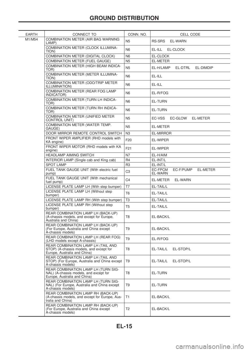
EARTH CONNECT TO CONN. NO. CELL CODE
M1/M54 COMBINATION METER (AIR BAG WARNING
LAMP)N5 RS-SRS EL-WARN
COMBINATION METER (CLOCK ILLUMINA-
TION)N6 EL-ILL EL-CLOCK
COMBINATION METER (DIGITAL CLOCK) N6 EL-CLOCK
COMBINATION METER (FUEL GAUGE) N5 EL-METER
COMBINATION METER (HIGH BEAM INDICA-
TOR)N5 EL-H/LAMP EL-DTRL EL-DIMDIP
COMBINATION METER (METER ILLUMINA-
TION)N6 EL-ILL
COMBINATION METER (ODO/TRIP METER
ILLUMINATION)N6 EL-ILL
COMBINATION METER (REAR FOG LAMP
INDICATOR)N6 EL-R/FOG
COMBINATION METER (TURN LH INDICA-
TOR)N6 EL-TURN
COMBINATION METER (TURN RH INDICA-
TOR)N6 EL-TURN
COMBINATION METER (UNIFIED METER
CONTROL UNIT)N5 EC-VSS EC-GLOW EL-METER
COMBINATION METER (WATER TEMP.
GAUGE)N5 EL-METER
DOOR MIRROR REMOTE CONTROL SWITCH N3 EL-MIRROR
FRONT WIPER AMPLIFIER (RHD models with
KA engine)F20 EL-WIPER
FRONT WIPER MOTOR (RHD models with KA
engine)F21 EL-WIPER
HEADLAMP AIMING SWITCH N7 EL-H/AIM
INTERIOR LAMP (Single cab and King cab) R4 EL-INT/L
SPOT LAMP R3 EL-INT/L
FUEL TANK GAUGE UNIT (With electric fuel
pump)C3EC-FPCM EC-F/PUMP EL-METER
EL-WARN
FUEL TANK GAUGE UNIT (With mechanical
fuel pump)C4 EL-METER EL-WARN
LICENSE PLATE LAMP LH (With step bumper) T7 EL-TAIL/L
LICENSE PLATE LAMP LH (Without step
bumper)T6 EL-TAIL/L
LICENSE PLATE LAMP RH (With step bumper) T3 EL-TAIL/L
LICENSE PLATE LAMP RH (Without step
bumper)T5 EL-TAIL/L
REAR COMBINATION LAMP LH (BACK-UP)
(A-chassis models, and except for Europe,
Australia and China)T8 EL-BACK/L
REAR COMBINATION LAMP LH (BACK-UP)
(For Europe, Australia and China except
A-chassis models)T9 EL-BACK/L
REAR COMBINATION LAMP LH (REAR FOG)
(LHD models except A-chassis)T9 EL-R/FOG
REAR COMBINATION LAMP LH (TAIL AND
STOP) (A-chassis models, and except for
Europe, Australia and China)T8 EL-TAIL/L EL-STOP/L
REAR COMBINATION LAMP LH (TAIL AND
STOP) (For Europe, Australia and China except
A-chassis models)T9 EL-TAIL/L EL-STOP/L
REAR COMBINATION LAMP LH (TURN SIG-
NAL) (A-chassis models, and except for
Europe, Australia and China)T8 EL-TURN
REAR COMBINATION LAMP LH (TURN SIG-
NAL) (For Europe, Australia and China except
A-chassis models)T9 EL-TURN
REAR COMBINATION LAMP RH (BACK-UP)
(A-chassis models, and except for Europe, Aus-
tralia and China)T1 EL-BACK/L
REAR COMBINATION LAMP RH (BACK-UP)
(For Europe, Australia and China except
A-chassis models)T2 EL-BACK/L
GROUND DISTRIBUTION
EL-15
Page 406 of 1659
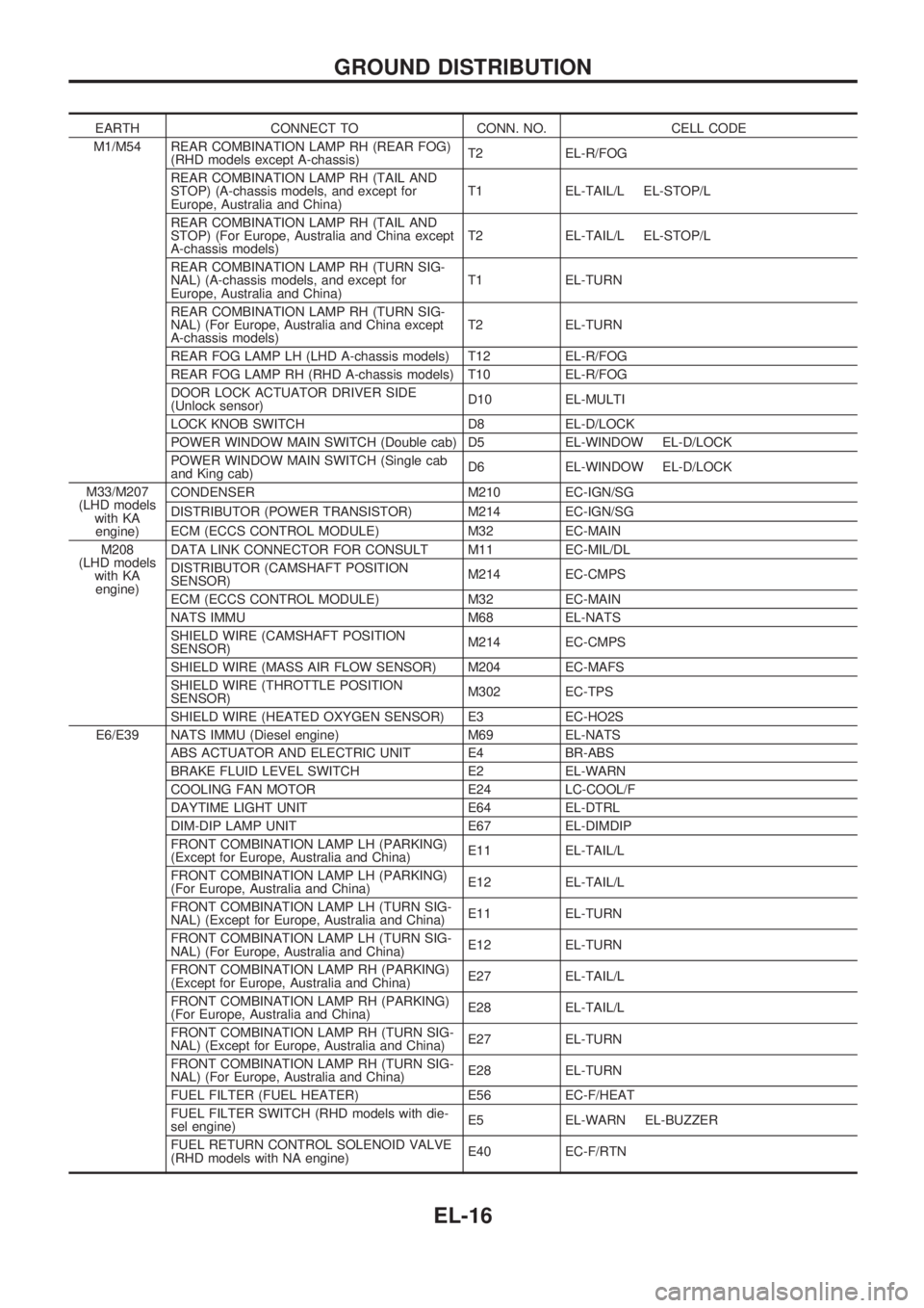
EARTH CONNECT TO CONN. NO. CELL CODE
M1/M54 REAR COMBINATION LAMP RH (REAR FOG)
(RHD models except A-chassis)T2 EL-R/FOG
REAR COMBINATION LAMP RH (TAIL AND
STOP) (A-chassis models, and except for
Europe, Australia and China)T1 EL-TAIL/L EL-STOP/L
REAR COMBINATION LAMP RH (TAIL AND
STOP) (For Europe, Australia and China except
A-chassis models)T2 EL-TAIL/L EL-STOP/L
REAR COMBINATION LAMP RH (TURN SIG-
NAL) (A-chassis models, and except for
Europe, Australia and China)T1 EL-TURN
REAR COMBINATION LAMP RH (TURN SIG-
NAL) (For Europe, Australia and China except
A-chassis models)T2 EL-TURN
REAR FOG LAMP LH (LHD A-chassis models) T12 EL-R/FOG
REAR FOG LAMP RH (RHD A-chassis models) T10 EL-R/FOG
DOOR LOCK ACTUATOR DRIVER SIDE
(Unlock sensor)D10 EL-MULTI
LOCK KNOB SWITCH D8 EL-D/LOCK
POWER WINDOW MAIN SWITCH (Double cab) D5 EL-WINDOW EL-D/LOCK
POWER WINDOW MAIN SWITCH (Single cab
and King cab)D6 EL-WINDOW EL-D/LOCK
M33/M207
(LHD models
with KA
engine)CONDENSER M210 EC-IGN/SG
DISTRIBUTOR (POWER TRANSISTOR) M214 EC-IGN/SG
ECM (ECCS CONTROL MODULE) M32 EC-MAIN
M208
(LHD models
with KA
engine)DATA LINK CONNECTOR FOR CONSULT M11 EC-MIL/DL
DISTRIBUTOR (CAMSHAFT POSITION
SENSOR)M214 EC-CMPS
ECM (ECCS CONTROL MODULE) M32 EC-MAIN
NATS IMMU M68 EL-NATS
SHIELD WIRE (CAMSHAFT POSITION
SENSOR)M214 EC-CMPS
SHIELD WIRE (MASS AIR FLOW SENSOR) M204 EC-MAFS
SHIELD WIRE (THROTTLE POSITION
SENSOR)M302 EC-TPS
SHIELD WIRE (HEATED OXYGEN SENSOR) E3 EC-HO2S
E6/E39 NATS IMMU (Diesel engine) M69 EL-NATS
ABS ACTUATOR AND ELECTRIC UNIT E4 BR-ABS
BRAKE FLUID LEVEL SWITCH E2 EL-WARN
COOLING FAN MOTOR E24 LC-COOL/F
DAYTIME LIGHT UNIT E64 EL-DTRL
DIM-DIP LAMP UNIT E67 EL-DIMDIP
FRONT COMBINATION LAMP LH (PARKING)
(Except for Europe, Australia and China)E11 EL-TAIL/L
FRONT COMBINATION LAMP LH (PARKING)
(For Europe, Australia and China)E12 EL-TAIL/L
FRONT COMBINATION LAMP LH (TURN SIG-
NAL) (Except for Europe, Australia and China)E11 EL-TURN
FRONT COMBINATION LAMP LH (TURN SIG-
NAL) (For Europe, Australia and China)E12 EL-TURN
FRONT COMBINATION LAMP RH (PARKING)
(Except for Europe, Australia and China)E27 EL-TAIL/L
FRONT COMBINATION LAMP RH (PARKING)
(For Europe, Australia and China)E28 EL-TAIL/L
FRONT COMBINATION LAMP RH (TURN SIG-
NAL) (Except for Europe, Australia and China)E27 EL-TURN
FRONT COMBINATION LAMP RH (TURN SIG-
NAL) (For Europe, Australia and China)E28 EL-TURN
FUEL FILTER (FUEL HEATER) E56 EC-F/HEAT
FUEL FILTER SWITCH (RHD models with die-
sel engine)E5 EL-WARN EL-BUZZER
FUEL RETURN CONTROL SOLENOID VALVE
(RHD models with NA engine)E40 EC-F/RTN
GROUND DISTRIBUTION
EL-16
Page 544 of 1659
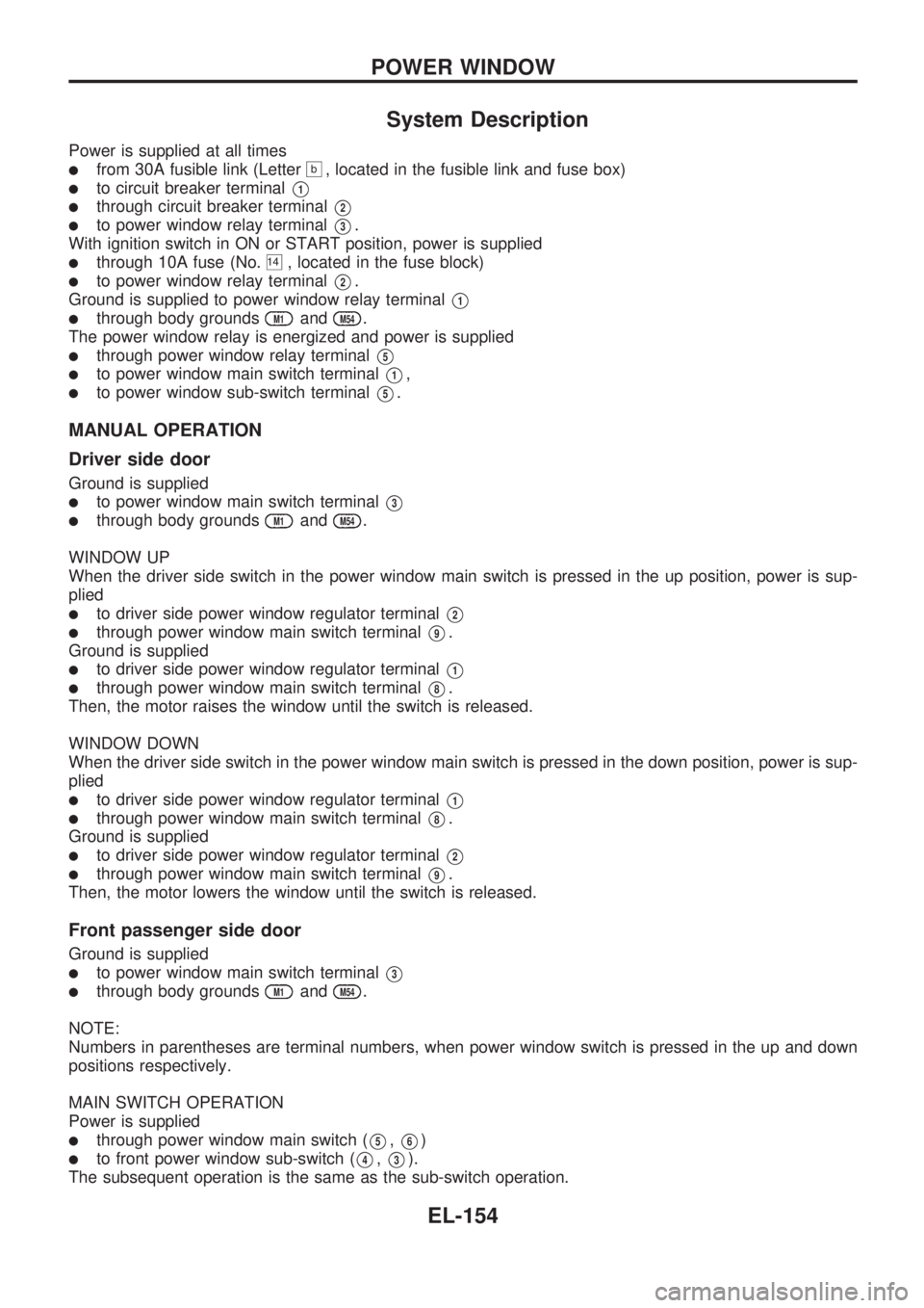
System Description
Power is supplied at all times
lfrom 30A fusible link (Letterb, located in the fusible link and fuse box)
lto circuit breaker terminalV1
lthrough circuit breaker terminalV2
lto power window relay terminalV3.
With ignition switch in ON or START position, power is supplied
lthrough 10A fuse (No.14, located in the fuse block)
lto power window relay terminalV2.
Ground is supplied to power window relay terminal
V1
lthrough body groundsM1andM54.
The power window relay is energized and power is supplied
lthrough power window relay terminalV5
lto power window main switch terminalV1,
lto power window sub-switch terminalV5.
MANUAL OPERATION
Driver side door
Ground is supplied
lto power window main switch terminalV3
lthrough body groundsM1andM54.
WINDOW UP
When the driver side switch in the power window main switch is pressed in the up position, power is sup-
plied
lto driver side power window regulator terminalV2
lthrough power window main switch terminalV9.
Ground is supplied
lto driver side power window regulator terminalV1
lthrough power window main switch terminalV8.
Then, the motor raises the window until the switch is released.
WINDOW DOWN
When the driver side switch in the power window main switch is pressed in the down position, power is sup-
plied
lto driver side power window regulator terminalV1
lthrough power window main switch terminalV8.
Ground is supplied
lto driver side power window regulator terminalV2
lthrough power window main switch terminalV9.
Then, the motor lowers the window until the switch is released.
Front passenger side door
Ground is supplied
lto power window main switch terminalV3
lthrough body groundsM1andM54.
NOTE:
Numbers in parentheses are terminal numbers, when power window switch is pressed in the up and down
positions respectively.
MAIN SWITCH OPERATION
Power is supplied
lthrough power window main switch (V5,V6)
lto front power window sub-switch (V4,V3).
The subsequent operation is the same as the sub-switch operation.
POWER WINDOW
EL-154
Page 545 of 1659
SUB-SWITCH OPERATION
Power is supplied
lthrough front power window sub-switch (V2,V1)
lto front passenger side power window regulator (V2,V1).
Ground is supplied
lto front passenger side power window regulator (V1,V2)
lthrough front power window sub-switch (V1,V2)
lto front power window sub-switch (V3,V4)
lthrough power window main switch (V6,V5).
Then, the motor raises or lowers the window until the switch is released.
Rear door
Rear door windows will raise and lower in the same manner as front passenger side door window.
AUTO OPERATION
The power window AUTO feature enables the driver to open or close the driver's window without holding
the window switch in the respective position.
When the AUTO switch in the main switch is pressed and released, the driver's window will travel to the
fully open or closed position.
POWER WINDOW LOCK
The power window lock is designed to lock operation of all windows except for driver's door window.
When the lock switch is pressed to lock position, ground of the sub-switches in the power window main switch
is disconnected. This prevents the power window motors from operating.
POWER WINDOW
System Description (Cont'd)
EL-155
Page 556 of 1659
System Description
Power is supplied at all times
lthrough 30A fusible link (Letter (No.b, located in the fusible link and fuse box)
lto circuit breaker terminalV1
lthrough circuit breaker terminalV2
lto door lock timer terminalV3.
Ground is supplied to door lock timer terminal
V1through body groundsM1andM54.
INPUT
When the door lock & unlock switch (power window main switch) is in LOCKED position, ground signal is
supplied
lto door lock timer terminalV5
lthrough door lock & unlock switch terminalV14
lto door lock & unlock switch terminalV3
lthrough body groundsM1andM54.
When the door lock & unlock switch (power window main switch) is in UNLOCKED position, ground signal
is supplied
lto door lock timer terminalV8
lthrough door lock & unlock switch terminalV7
lto door lock & unlock switch terminalV3
lthrough body groundsM1andM54.
Driver side door key cylinder and driver side lock knob are connected to lock knob switch with a rod. When
lock knob switch is in UNLOCKED position, ground signal is supplied
lto door lock timer terminalV6
lthrough lock knob switch terminalV2
lto driver side lock knob switch terminalV1
lthrough body groundsM1andM54.
When lock knob switch is in LOCKED position, ground signal is interrupted.
Door lock operates according to the conditions of the door lock & unlock switch (power window main switch)
and lock knob switch.
OUTPUT
Unlock
Ground is supplied
lto passenger side door lock actuator, rear door lock actuator LH and RH terminalV1(double cab mod-
els)
lthrough door lock timer terminalV2.
Power is supplied
lto passenger side door lock actuator, rear door lock actuator LH and RH terminalV2(double cab mod-
els)
lthrough door lock timer terminalV4.
Then, the doors are unlocked.
Lock
Ground is supplied
lto passenger side door lock actuator, rear door lock actuator LH and RH terminalV2
lthrough door lock timer terminalV4.
Power is supplied
lto passenger side door lock actuator, rear door lock actuator LH and RH terminalV1
lthrough door lock timer terminalV2.
Then, the doors are locked.
POWER DOOR LOCK
EL-166