heater NISSAN PICK-UP 1998 Repair Manual
[x] Cancel search | Manufacturer: NISSAN, Model Year: 1998, Model line: PICK-UP, Model: NISSAN PICK-UP 1998Pages: 1659, PDF Size: 53.39 MB
Page 1 of 1659
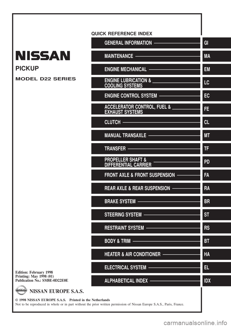
GENERAL INFORMATIONGI
MAINTENANCEMA
ENGINE MECHANICALEM
ENGINE LUBRICATION &
COOLING SYSTEMSLC
ENGINE CONTROL SYSTEMEC
ACCELERATOR CONTROL, FUEL &
EXHAUST SYSTEMSFE
CLUTCHCL
MANUAL TRANSAXLEMT
TRANSFERTF
PROPELLER SHAFT &
DIFFERENTIAL CARRIERPD
FRONT AXLE & FRONT SUSPENSIONFA
REAR AXLE & REAR SUSPENSIONRA
BRAKE SYSTEMBR
STEERING SYSTEMST
RESTRAINT SYSTEMRS
BODY & TRIMBT
HEATER & AIR CONDITIONERHA
ELECTRICAL SYSTEMEL
ALPHABETICAL INDEXIDX
PICKUP
MODEL D22 SERIES
Edition: February 1998
Printing: May 1998 (01)
Publication No.: SM8E-0D22E0E
NISSAN EUROPE S.A.S.
1998 NISSAN EUROPE S.A.S. Printed in the Netherlands
Not to be reproduced in whole or in part without the prior written permission of Nissan Europe S.A.S., Paris, France.
QUICK REFERENCE INDEX
Page 112 of 1659
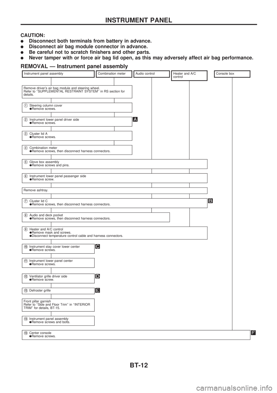
CAUTION:
lDisconnect both terminals from battery in advance.
lDisconnect air bag module connector in advance.
lBe careful not to scratch finishers and other parts.
lNever tamper with or force air bag lid open, as this may adversely affect air bag performance.
REMOVAL Ð Instrument panel assembly
Instrument panel assemblyCombination meterAudio controlHeater and A/C
controlConsole box
Remove driver's air bag module and steering wheel.
Refer to ``SUPPLEMENTAL RESTRAINT SYSTEM'' in RS section for
details.
V1Steering column coverlRemove screws.
V2Instrument lower panel driver sidelRemove screws.
V3Cluster lid AlRemove screws.
V4Combination meterlRemove screws, then disconnect harness connectors.
V5Glove box assemblylRemove screws and pins.
V6Instrument lower panel passenger sidelRemove screw.
Remove ashtray.
V7Cluster lid ClRemove screws, then disconnect harness connectors.
V8Audio and deck pocketlRemove screws, then disconnect harness connectors.
V9Heater and A/C controllRemove mask and screws.lDisconnect temperature control cable and harness connectors.
V10Instrument stay cover lower centerlRemove screws.
V11Instrument lower panel centerlRemove screws.
V12Ventilator grille driver sidelRemove screw.
V13Defroster grille
Front pillar garnish
Refer to ``Side and Floor Trim'' in ``INTERIOR
TRIM'' for details, BT-15.
V14Instrument panel assemblylRemove screws and bolts.
V15Center consolelRemove screws.
INSTRUMENT PANEL
BT-12
Page 151 of 1659
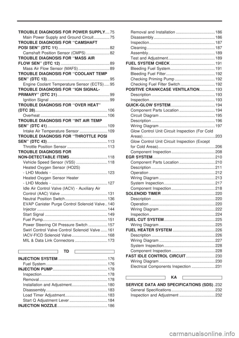
TROUBLE DIAGNOSIS FOR POWER SUPPLY.... 75
Main Power Supply and Ground Circuit .............. 75
TROUBLE DIAGNOSIS FOR ``CAMSHAFT
POSI SEN'' (DTC 11).............................................. 82
Camshaft Position Sensor (CMPS) ..................... 82
TROUBLE DIAGNOSIS FOR ``MASS AIR
FLOW SEN'' (DTC 12)............................................ 89
Mass Air Flow Sensor (MAFS) ............................ 89
TROUBLE DIAGNOSIS FOR ``COOLANT TEMP
SEN'' (DTC 13)........................................................ 95
Engine Coolant Temperature Sensor (ECTS) ..... 95
TROUBLE DIAGNOSIS FOR ``IGN SIGNAL-
PRIMARY'' (DTC 21)............................................... 99
Ignition Signal ...................................................... 99
TROUBLE DIAGNOSIS FOR ``OVER HEAT''
(DTC 28)................................................................. 106
Overheat ............................................................ 106
TROUBLE DIAGNOSIS FOR ``INT AIR TEMP
SEN'' (DTC 41)...................................................... 109
Intake Air Temperature Sensor ......................... 109
TROUBLE DIAGNOSIS FOR ``THROTTLE POSI
SEN'' (DTC 43)...................................................... 113
Throttle Position Sensor .................................... 113
TROUBLE DIAGNOSIS FOR
NON-DETECTABLE ITEMS.................................. 118
Vehicle Speed Sensor (VSS) ............................ 118
Heated Oxygen Sensor (HO2S)
- LHD Models - .................................................. 123
Heated Oxygen Sensor Heater
- LHD Models - .................................................. 127
Idle Air Control Valve (IACV) - Auxiliary Air
Control (AAC) Valve .......................................... 131
Neutral Position Switch ...................................... 136
EVAP Canister Purge Control Solenoid Valve .. 140
Injector ............................................................... 144
Start Signal ........................................................ 149
Fuel Pump.......................................................... 151
Power Steering Oil Pressure Switch ................. 157
Swirl Control Valve Control Solenoid Valve ...... 161
IACV-FICD Solenoid Valve ................................ 168
MIL & Data Link Connectors ............................. 173
TD
INJECTION SYSTEM............................................ 176
Fuel System ....................................................... 176
INJECTION PUMP................................................. 178
Inspection ........................................................... 178
Removal ............................................................. 178
Installation and Adjustment................................ 180
Disassembly ....................................................... 183
Load Timer Adjustment...................................... 183
Start Q Adjustment Lever .................................. 184
INJECTION NOZZLE............................................. 186Removal and Installation ................................... 186
Disassembly ....................................................... 186
Inspection ........................................................... 187
Cleaning ............................................................. 187
Assembly............................................................ 189
Test and Adjustment .......................................... 189
FUEL SYSTEM CHECK........................................ 191
Bleeding Fuel System ........................................ 191
Bleeding Fuel Filter ............................................ 192
Checking Priming Pump .................................... 192
Checking Fuel Filter Switch ............................... 192
POSITIVE CRANKCASE VENTILATION.............. 193
Description ......................................................... 193
Inspection ........................................................... 193
QUICK-GLOW SYSTEM........................................ 194
Component Parts Location ................................ 194
Circuit Diagram .................................................. 195
Description ......................................................... 196
Wiring Diagram .................................................. 197
Glow Control Unit Circuit Inspection (For Cold
Areas)................................................................. 203
Glow Control Unit Circuit Inspection (Except
for Cold Areas)................................................... 206
Component Inspection ....................................... 208
EGR SYSTEM........................................................ 210
Component Parts Location ................................ 210
Description ......................................................... 211
Operation ........................................................... 212
Wiring Diagram .................................................. 213
System Inspection.............................................. 217
Component Inspection ....................................... 218
SOLENOID TIMER................................................ 220
Description ......................................................... 220
Operation ........................................................... 220
Wiring Diagram .................................................. 222
Inspection ........................................................... 224
FUEL CUT SYSTEM.............................................. 225
Wiring Diagram .................................................. 225
FUEL HEATER SYSTEM...................................... 226
Description ......................................................... 226
Wiring Diagram .................................................. 227
System Inspection.............................................. 228
Component Inspection ....................................... 228
FAST IDLE CONTROL CIRCUIT.......................... 230
Wiring Diagram .................................................. 230
Electrical Components Inspection ..................... 231
KA
SERVICE DATA AND SPECIFICATIONS (SDS). 232
General Specifications ....................................... 232
Inspection and Adjustment ................................ 232
Page 165 of 1659
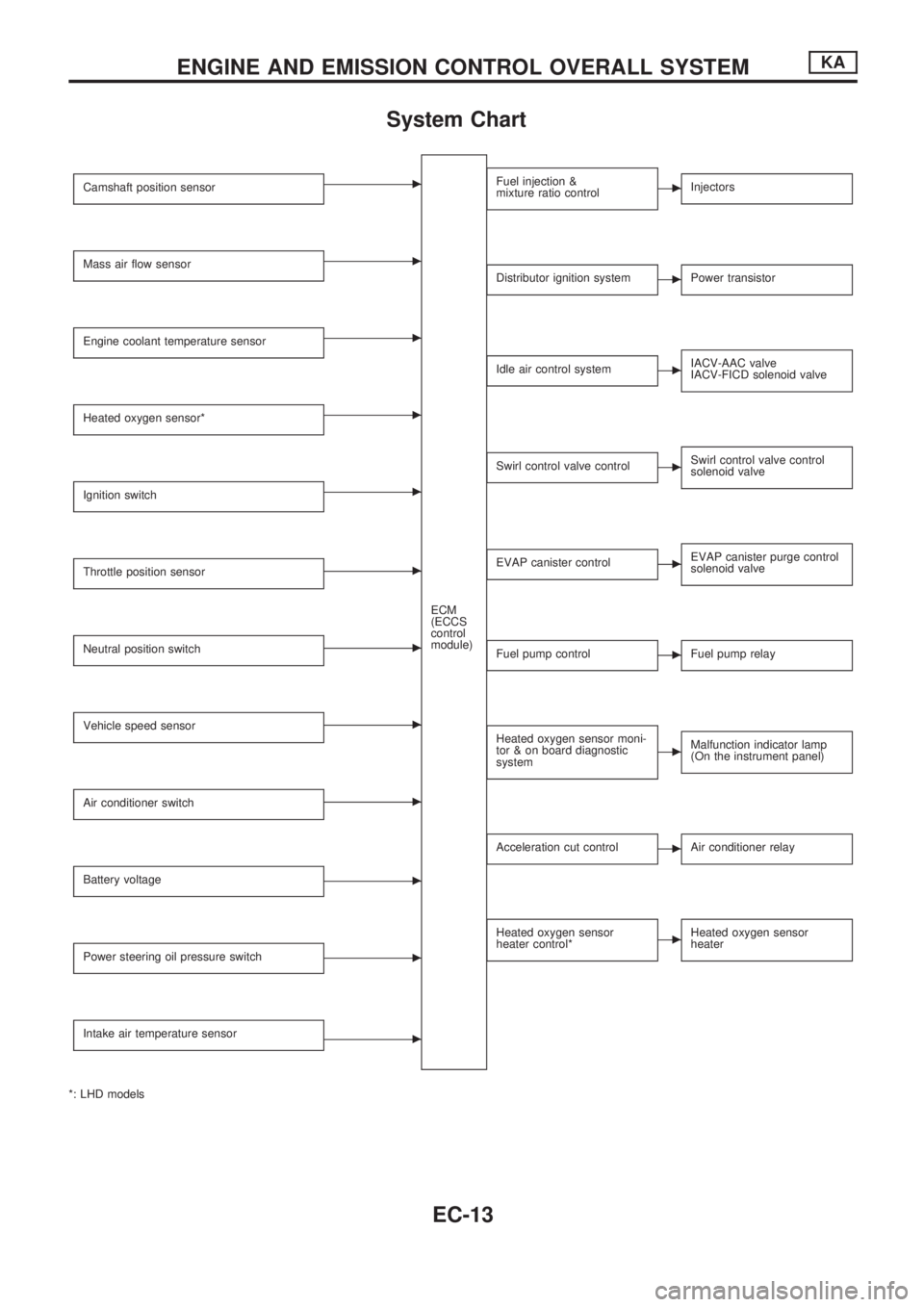
System Chart
Camshaft position sensorc
ECM
(ECCS
control
module)
Mass air flow sensorc
Engine coolant temperature sensorc
Heated oxygen sensor*c
Ignition switchc
Throttle position sensorc
Neutral position switchc
Vehicle speed sensorc
Air conditioner switchc
Battery voltagec
Power steering oil pressure switchc
Intake air temperature sensorc
*: LHD models
Fuel injection &
mixture ratio controlcInjectors
Distributor ignition systemcPower transistor
Idle air control systemcIACV-AAC valve
IACV-FICD solenoid valve
Swirl control valve controlcSwirl control valve control
solenoid valve
EVAP canister controlcEVAP canister purge control
solenoid valve
Fuel pump controlcFuel pump relay
Heated oxygen sensor moni-
tor & on board diagnostic
systemcMalfunction indicator lamp
(On the instrument panel)
Acceleration cut controlcAir conditioner relay
Heated oxygen sensor
heater control*cHeated oxygen sensor
heater
ENGINE AND EMISSION CONTROL OVERALL SYSTEMKA
EC-13
Page 177 of 1659
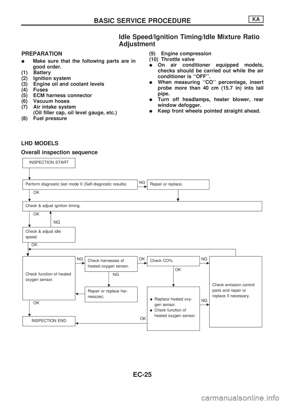
Idle Speed/Ignition Timing/Idle Mixture Ratio
Adjustment
PREPARATION
lMake sure that the following parts are in
good order.
(1) Battery
(2) Ignition system
(3) Engine oil and coolant levels
(4) Fuses
(5) ECM harness connector
(6) Vacuum hoses
(7) Air intake system
(Oil filler cap, oil level gauge, etc.)
(8) Fuel pressure(9) Engine compression
(10) Throttle valvelOn air conditioner equipped models,
checks should be carried out while the air
conditioner is ``OFF''.
lWhen measuring ``CO'' percentage, insert
probe more than 40 cm (15.7 in) into tail
pipe.
lTurn off headlamps, heater blower, rear
window defogger.
lKeep front wheels pointed straight ahead.
LHD MODELS
Overall inspection sequence
INSPECTION START
Perform diagnostic test mode II (Self-diagnostic results).
OK
cNG
Repair or replace.
.
Check & adjust ignition timing.
OKm
NG
Check & adjust idle
speed.
.
OKb
Check function of heated
oxygen sensor.
OK
cNG
Check harnesses of
heated oxygen sensor.
NG
cOK
Check CO%.
OK
.
cNG
Check emission control
parts and repair or
replace if necessary.
bRepair or replace har-
ness(es).
lReplace heated oxy-
gen sensor.
lCheck function of
heated oxygen sensor.
cNG
INSPECTION END
bOK
.
.
.
.
.
BASIC SERVICE PROCEDUREKA
EC-25
Page 225 of 1659
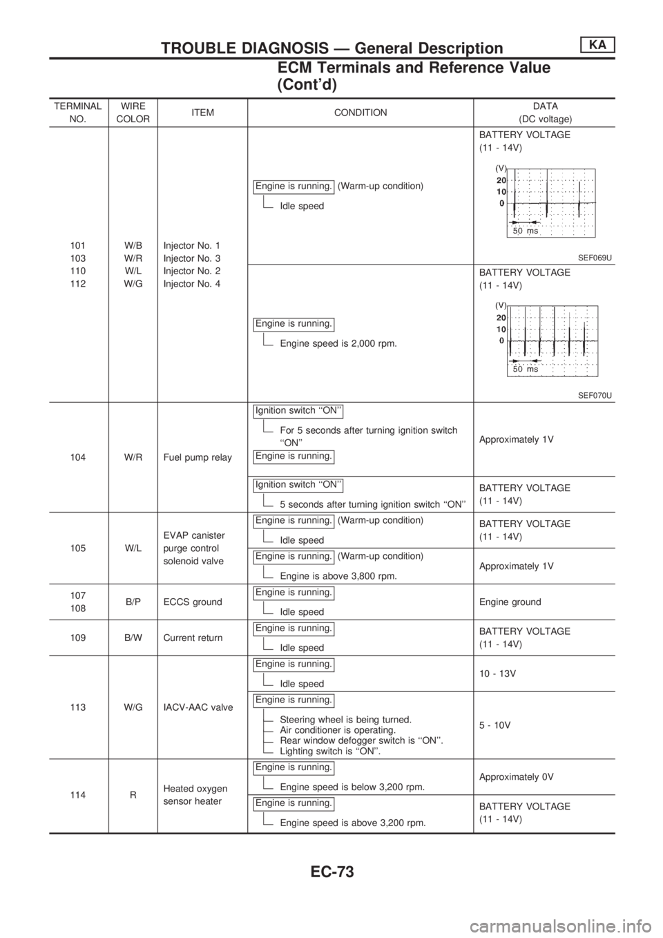
TERMINAL
NO.WIRE
COLORITEM CONDITIONDATA
(DC voltage)
101
103
110
112W/B
W/R
W/L
W/GInjector No. 1
Injector No. 3
Injector No. 2
Injector No. 4Engine is running.
(Warm-up condition)
Idle speedBATTERY VOLTAGE
(11 - 14V)
SEF069U
Engine is running.
Engine speed is 2,000 rpm.BATTERY VOLTAGE
(11 - 14V)
SEF070U
104 W/R Fuel pump relayIgnition switch ``ON''
For 5 seconds after turning ignition switch
``ON''
Engine is running.Approximately 1V
Ignition switch ``ON''
5 seconds after turning ignition switch ``ON''BATTERY VOLTAGE
(11 - 14V)
105 W/LEVAP canister
purge control
solenoid valveEngine is running.
(Warm-up condition)
Idle speedBATTERY VOLTAGE
(11 - 14V)
Engine is running.
(Warm-up condition)
Engine is above 3,800 rpm.Approximately 1V
107
108B/P ECCS groundEngine is running.
Idle speedEngine ground
109 B/W Current returnEngine is running.
Idle speedBATTERY VOLTAGE
(11 - 14V)
113 W/G IACV-AAC valveEngine is running.
Idle speed10 - 13V
Engine is running.
Steering wheel is being turned.Air conditioner is operating.Rear window defogger switch is ``ON''.Lighting switch is ``ON''.5 - 10V
114 RHeated oxygen
sensor heaterEngine is running.
Engine speed is below 3,200 rpm.Approximately 0V
Engine is running.
Engine speed is above 3,200 rpm.BATTERY VOLTAGE
(11 - 14V)
TROUBLE DIAGNOSIS Ð General DescriptionKA
ECM Terminals and Reference Value
(Cont'd)
EC-73
Page 279 of 1659
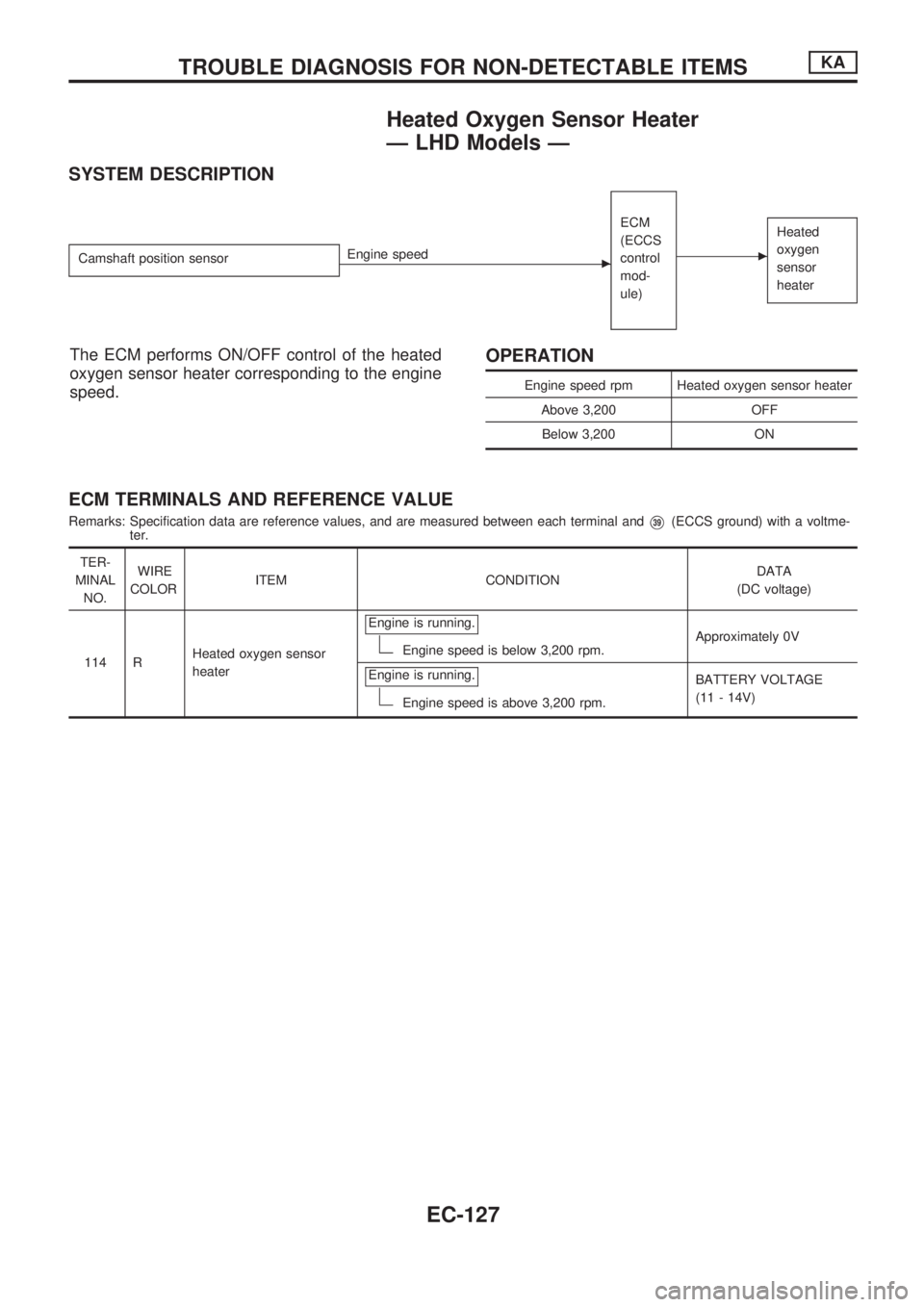
Heated Oxygen Sensor Heater
Ð LHD Models Ð
SYSTEM DESCRIPTION
Camshaft position sensorcEngine speedECM
(ECCS
control
mod-
ule)c
Heated
oxygen
sensor
heater
The ECM performs ON/OFF control of the heated
oxygen sensor heater corresponding to the engine
speed.OPERATION
Engine speed rpm Heated oxygen sensor heater
Above 3,200 OFF
Below 3,200 ON
ECM TERMINALS AND REFERENCE VALUE
Remarks: Specification data are reference values, and are measured between each terminal andV39(ECCS ground) with a voltme-
ter.
TER-
MINAL
NO.WIRE
COLORITEM CONDITIONDATA
(DC voltage)
114 RHeated oxygen sensor
heaterEngine is running.
Engine speed is below 3,200 rpm.Approximately 0V
Engine is running.
Engine speed is above 3,200 rpm.BATTERY VOLTAGE
(11 - 14V)
TROUBLE DIAGNOSIS FOR NON-DETECTABLE ITEMSKA
EC-127
Page 280 of 1659
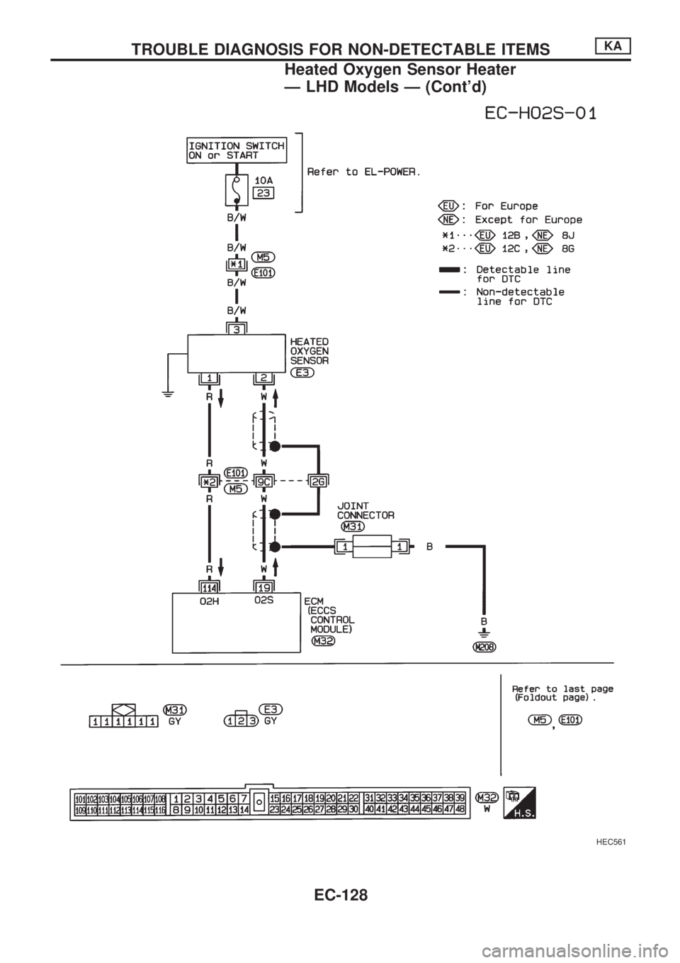
HEC561
TROUBLE DIAGNOSIS FOR NON-DETECTABLE ITEMSKA
Heated Oxygen Sensor Heater
Ð LHD Models Ð (Cont'd)
EC-128
Page 281 of 1659
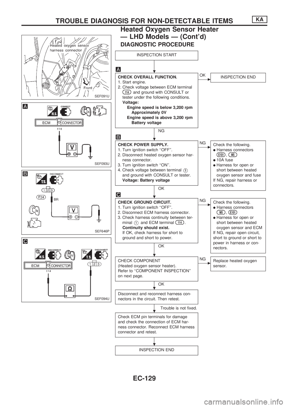
DIAGNOSTIC PROCEDURE
INSPECTION START
CHECK OVERALL FUNCTION.
1. Start engine.
2. Check voltage between ECM terminal
114and ground with CONSULT or
tester under the following conditions.
Voltage:
Engine speed is below 3,200 rpm
Approximately 0V
Engine speed is above 3,200 rpm
Battery voltage
NG
cOK
INSPECTION END
CHECK POWER SUPPLY.
1. Turn ignition switch ``OFF''.
2. Disconnect heated oxygen sensor har-
ness connector.
3. Turn ignition switch ``ON''.
4. Check voltage between terminal
V3
and ground with CONSULT or tester.
Voltage: Battery voltage
OK
cNG
Check the following.
lHarness connectorsE101,M5
l10A fuse
lHarness for open or
short between heated
oxygen sensor and fuse
If NG, repair harness or
connectors.
CHECK GROUND CIRCUIT.
1. Turn ignition switch ``OFF''.
2. Disconnect ECM harness connector.
3. Check harness continuity between ter-
minal
V1and ECM terminal114.
Continuity should exist.
If OK, check harness for short to
ground and short to power.
OK
cNG
Check the following.
lHarness connectorsM5,E101
lHarness for open or
short between heated
oxygen sensor and ECM
If NG, repair open circuit,
short to ground or short to
power in harness or con-
nectors.
CHECK COMPONENT
(Heated oxygen sensor heater).
Refer to ``COMPONENT INSPECTION''
on next page.
OK
cNG
Replace heated oxygen
sensor.
Disconnect and reconnect harness con-
nectors in the circuit. Then retest.
Trouble is not fixed.
Check ECM pin terminals for damage
and check the connection of ECM har-
ness connector. Reconnect ECM harness
connector and retest.
INSPECTION END
SEF091U
SEF093U
SEF646P
SEF094U
.
.
.
.
.
.
.
TROUBLE DIAGNOSIS FOR NON-DETECTABLE ITEMSKA
Heated Oxygen Sensor Heater
Ð LHD Models Ð (Cont'd)
EC-129
Page 282 of 1659
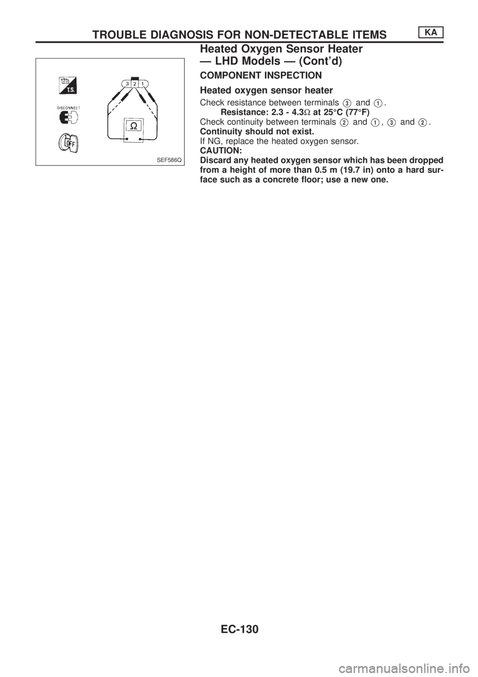
COMPONENT INSPECTION
Heated oxygen sensor heater
Check resistance between terminalsV3andV1.
Resistance: 2.3 - 4.3Wat 25ÉC (77ÉF)
Check continuity between terminals
V2andV1,V3andV2.
Continuity should not exist.
If NG, replace the heated oxygen sensor.
CAUTION:
Discard any heated oxygen sensor which has been dropped
from a height of more than 0.5 m (19.7 in) onto a hard sur-
face such as a concrete floor; use a new one.
SEF586Q
TROUBLE DIAGNOSIS FOR NON-DETECTABLE ITEMSKA
Heated Oxygen Sensor Heater
Ð LHD Models Ð (Cont'd)
EC-130