ECU NISSAN PICK-UP 1999 Repair Manual
[x] Cancel search | Manufacturer: NISSAN, Model Year: 1999, Model line: PICK-UP, Model: NISSAN PICK-UP 1999Pages: 666, PDF Size: 16.21 MB
Page 138 of 666
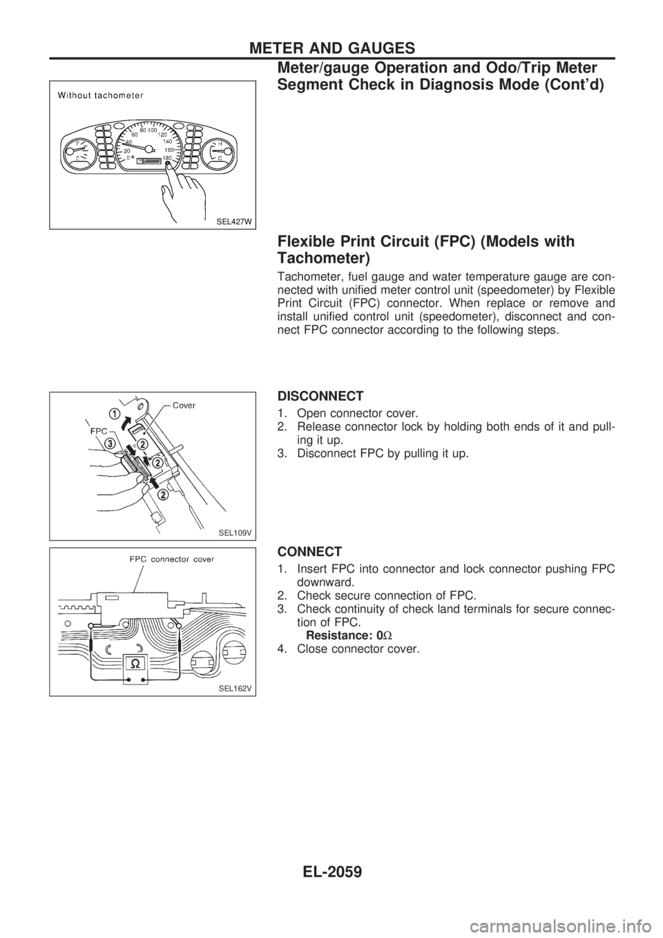
Flexible Print Circuit (FPC) (Models with
Tachometer)
Tachometer, fuel gauge and water temperature gauge are con-
nected with unified meter control unit (speedometer) by Flexible
Print Circuit (FPC) connector. When replace or remove and
install unified control unit (speedometer), disconnect and con-
nect FPC connector according to the following steps.
DISCONNECT
1. Open connector cover.
2. Release connector lock by holding both ends of it and pull-
ing it up.
3. Disconnect FPC by pulling it up.
CONNECT
1. Insert FPC into connector and lock connector pushing FPC
downward.
2. Check secure connection of FPC.
3. Check continuity of check land terminals for secure connec-
tion of FPC.
Resistance: 0W
4. Close connector cover.
SEL427W
SEL109V
SEL162V
METER AND GAUGES
Meter/gauge Operation and Odo/Trip Meter
Segment Check in Diagnosis Mode (Cont'd)
EL-2059
Page 139 of 666
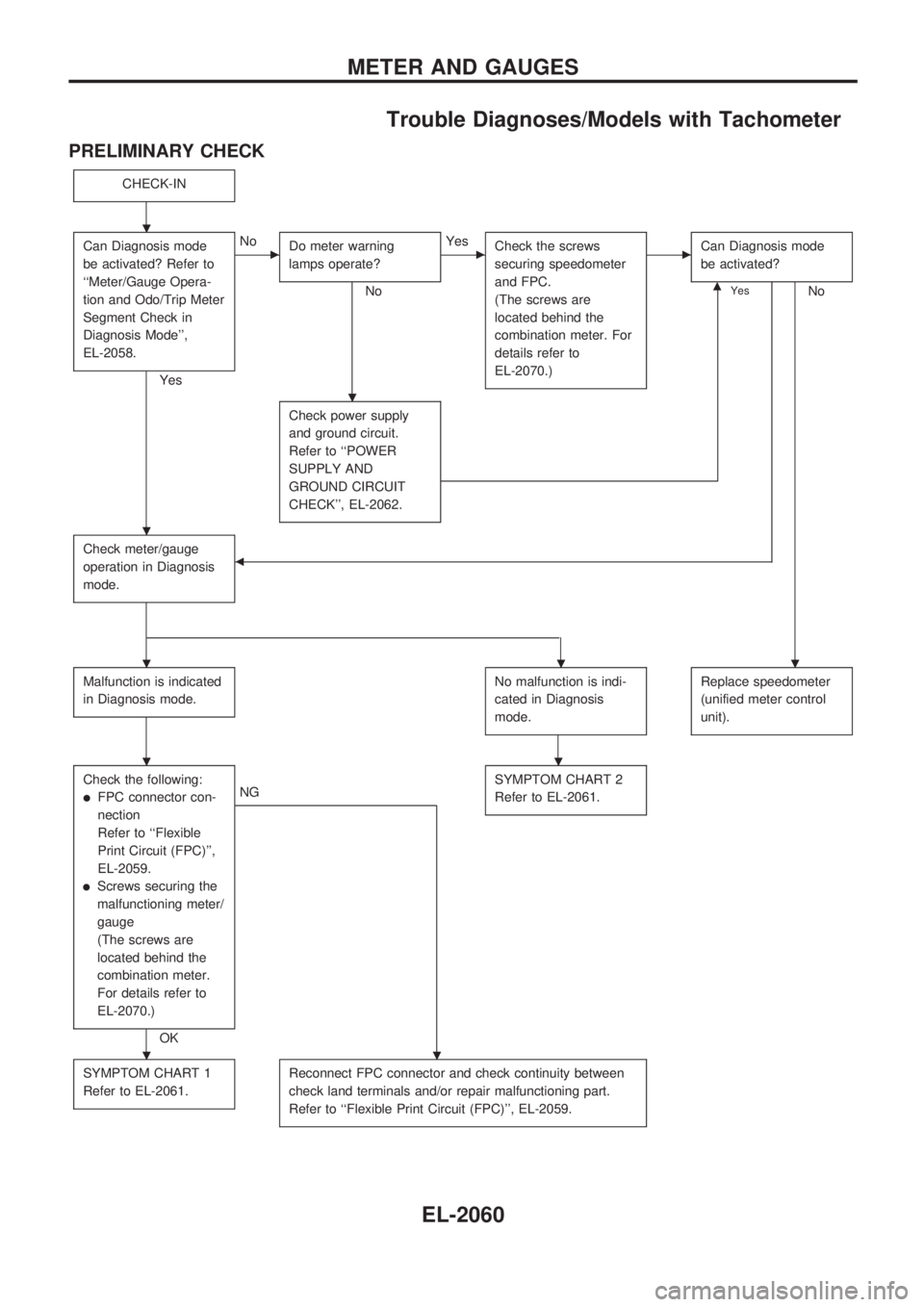
Trouble Diagnoses/Models with Tachometer
PRELIMINARY CHECK
CHECK-IN
Can Diagnosis mode
be activated? Refer to
``Meter/Gauge Opera-
tion and Odo/Trip Meter
Segment Check in
Diagnosis Mode'',
EL-2058.
Yes
cNo
Do meter warning
lamps operate?
No
cYes
Check the screws
securing speedometer
and FPC.
(The screws are
located behind the
combination meter. For
details refer to
EL-2070.)cCan Diagnosis mode
be activated?
NomYes
Check power supply
and ground circuit.
Refer to ``POWER
SUPPLY AND
GROUND CIRCUIT
CHECK'', EL-2062.
Check meter/gauge
operation in Diagnosis
mode.b
Malfunction is indicated
in Diagnosis mode.No malfunction is indi-
cated in Diagnosis
mode.Replace speedometer
(unified meter control
unit).
Check the following:
lFPC connector con-
nection
Refer to ``Flexible
Print Circuit (FPC)'',
EL-2059.
lScrews securing the
malfunctioning meter/
gauge
(The screws are
located behind the
combination meter.
For details refer to
EL-2070.)
OK
NGSYMPTOM CHART 2
Refer to EL-2061.
SYMPTOM CHART 1
Refer to EL-2061.Reconnect FPC connector and check continuity between
check land terminals and/or repair malfunctioning part.
Refer to ``Flexible Print Circuit (FPC)'', EL-2059.
.
.
.
...
..
..
METER AND GAUGES
EL-2060
Page 144 of 666
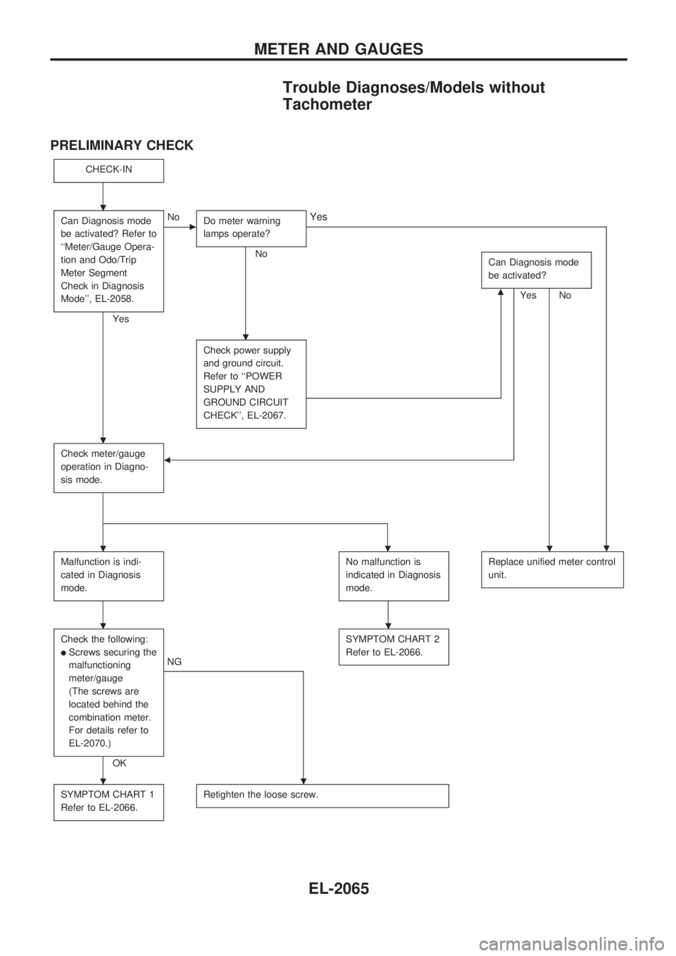
Trouble Diagnoses/Models without
Tachometer
PRELIMINARY CHECK
CHECK-IN
Can Diagnosis mode
be activated? Refer to
``Meter/Gauge Opera-
tion and Odo/Trip
Meter Segment
Check in Diagnosis
Mode'', EL-2058.
Yes
cNo
Do meter warning
lamps operate?
No
.
Yes
Can Diagnosis mode
be activated?
NomYes
Check power supply
and ground circuit.
Refer to ``POWER
SUPPLY AND
GROUND CIRCUIT
CHECK'', EL-2067.
Check meter/gauge
operation in Diagno-
sis mode.b
Malfunction is indi-
cated in Diagnosis
mode.No malfunction is
indicated in Diagnosis
mode.Replace unified meter control
unit.
Check the following:
lScrews securing the
malfunctioning
meter/gauge
(The screws are
located behind the
combination meter.
For details refer to
EL-2070.)
OK
NGSYMPTOM CHART 2
Refer to EL-2066.
SYMPTOM CHART 1
Refer to EL-2066.Retighten the loose screw.
.
.
.
...
..
..
METER AND GAUGES
EL-2065
Page 310 of 666
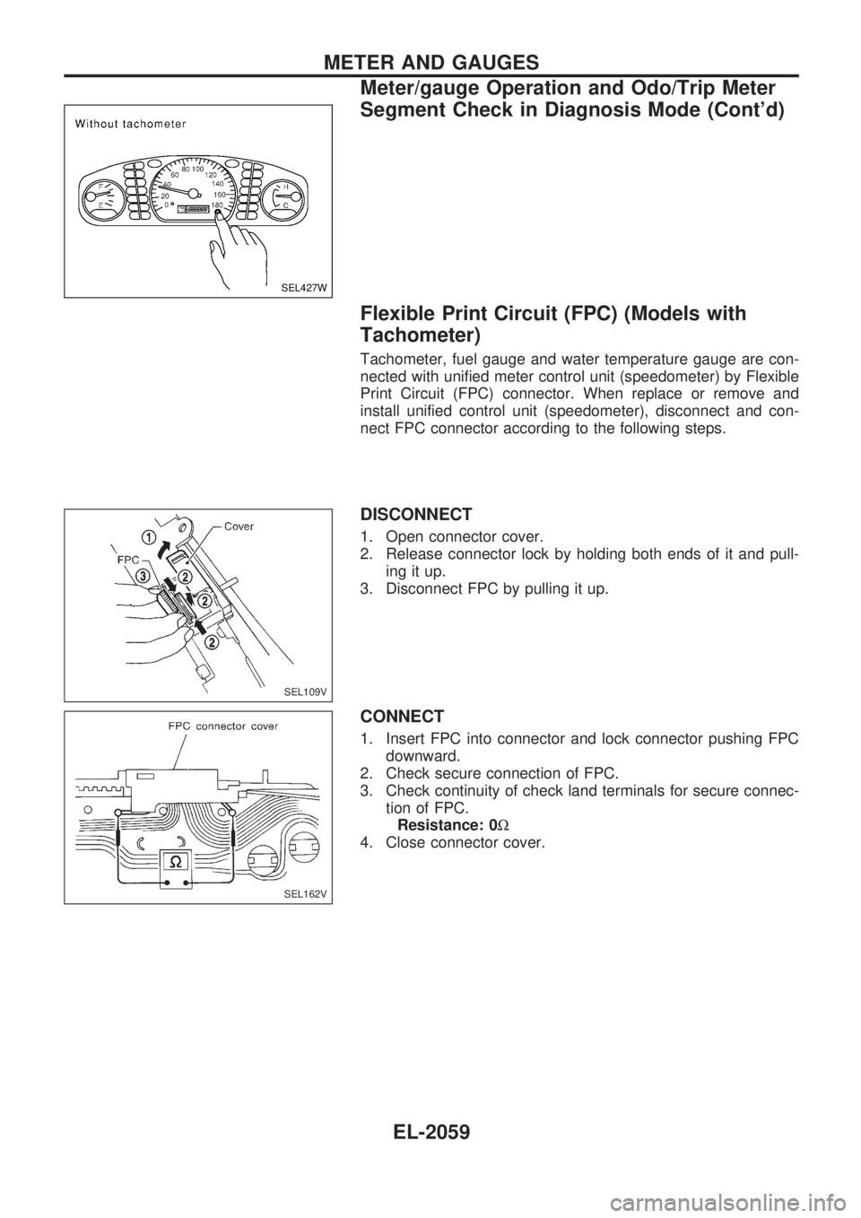
Flexible Print Circuit (FPC) (Models with
Tachometer)
Tachometer, fuel gauge and water temperature gauge are con-
nected with unified meter control unit (speedometer) by Flexible
Print Circuit (FPC) connector. When replace or remove and
install unified control unit (speedometer), disconnect and con-
nect FPC connector according to the following steps.
DISCONNECT
1. Open connector cover.
2. Release connector lock by holding both ends of it and pull-
ing it up.
3. Disconnect FPC by pulling it up.
CONNECT
1. Insert FPC into connector and lock connector pushing FPC
downward.
2. Check secure connection of FPC.
3. Check continuity of check land terminals for secure connec-
tion of FPC.
Resistance: 0W
4. Close connector cover.
SEL427W
SEL109V
SEL162V
METER AND GAUGES
Meter/gauge Operation and Odo/Trip Meter
Segment Check in Diagnosis Mode (Cont'd)
EL-2059
Page 311 of 666
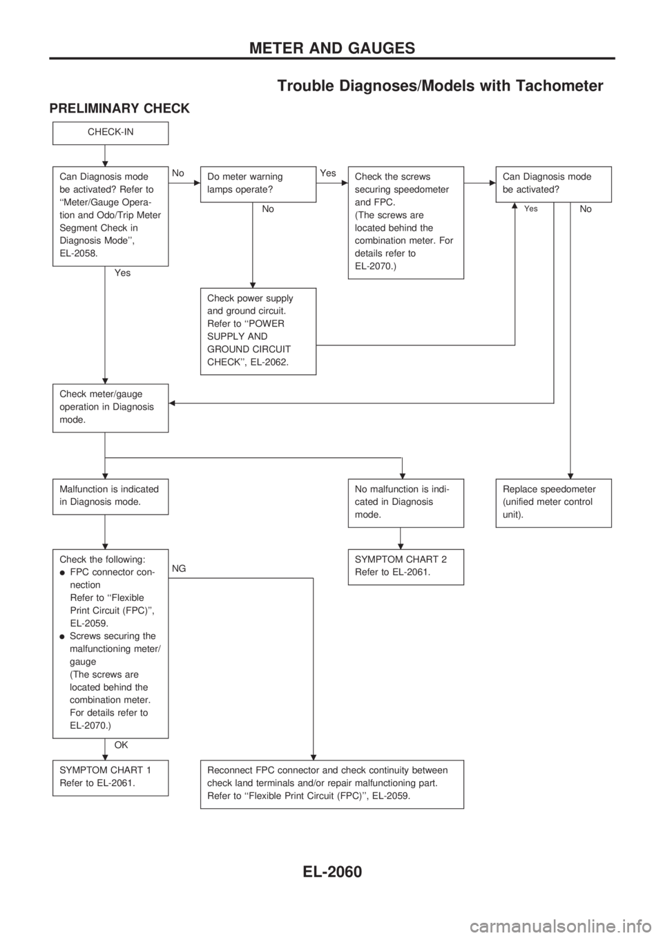
Trouble Diagnoses/Models with Tachometer
PRELIMINARY CHECK
CHECK-IN
Can Diagnosis mode
be activated? Refer to
``Meter/Gauge Opera-
tion and Odo/Trip Meter
Segment Check in
Diagnosis Mode'',
EL-2058.
Yes
cNo
Do meter warning
lamps operate?
No
cYes
Check the screws
securing speedometer
and FPC.
(The screws are
located behind the
combination meter. For
details refer to
EL-2070.)cCan Diagnosis mode
be activated?
NomYes
Check power supply
and ground circuit.
Refer to ``POWER
SUPPLY AND
GROUND CIRCUIT
CHECK'', EL-2062.
Check meter/gauge
operation in Diagnosis
mode.b
Malfunction is indicated
in Diagnosis mode.No malfunction is indi-
cated in Diagnosis
mode.Replace speedometer
(unified meter control
unit).
Check the following:
lFPC connector con-
nection
Refer to ``Flexible
Print Circuit (FPC)'',
EL-2059.
lScrews securing the
malfunctioning meter/
gauge
(The screws are
located behind the
combination meter.
For details refer to
EL-2070.)
OK
NGSYMPTOM CHART 2
Refer to EL-2061.
SYMPTOM CHART 1
Refer to EL-2061.Reconnect FPC connector and check continuity between
check land terminals and/or repair malfunctioning part.
Refer to ``Flexible Print Circuit (FPC)'', EL-2059.
.
.
.
...
..
..
METER AND GAUGES
EL-2060
Page 316 of 666
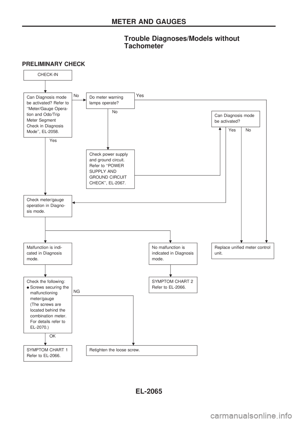
Trouble Diagnoses/Models without
Tachometer
PRELIMINARY CHECK
CHECK-IN
Can Diagnosis mode
be activated? Refer to
``Meter/Gauge Opera-
tion and Odo/Trip
Meter Segment
Check in Diagnosis
Mode'', EL-2058.
Yes
cNo
Do meter warning
lamps operate?
No
.
Yes
Can Diagnosis mode
be activated?
NomYes
Check power supply
and ground circuit.
Refer to ``POWER
SUPPLY AND
GROUND CIRCUIT
CHECK'', EL-2067.
Check meter/gauge
operation in Diagno-
sis mode.b
Malfunction is indi-
cated in Diagnosis
mode.No malfunction is
indicated in Diagnosis
mode.Replace unified meter control
unit.
Check the following:
lScrews securing the
malfunctioning
meter/gauge
(The screws are
located behind the
combination meter.
For details refer to
EL-2070.)
OK
NGSYMPTOM CHART 2
Refer to EL-2066.
SYMPTOM CHART 1
Refer to EL-2066.Retighten the loose screw.
.
.
.
...
..
..
METER AND GAUGES
EL-2065
Page 446 of 666
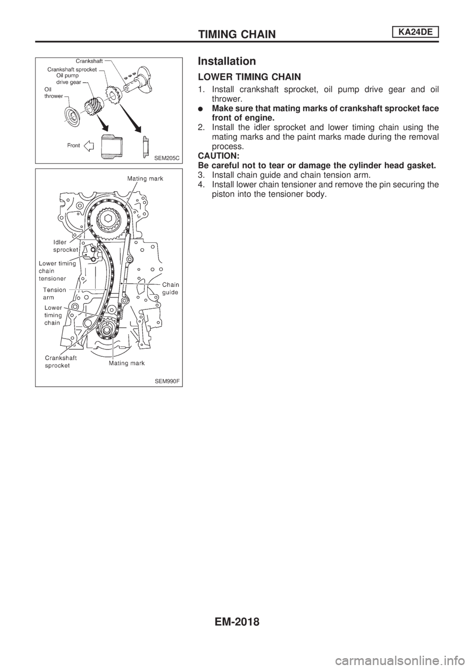
Installation
LOWER TIMING CHAIN
1. Install crankshaft sprocket, oil pump drive gear and oil
thrower.
lMake sure that mating marks of crankshaft sprocket face
front of engine.
2. Install the idler sprocket and lower timing chain using the
mating marks and the paint marks made during the removal
process.
CAUTION:
Be careful not to tear or damage the cylinder head gasket.
3. Install chain guide and chain tension arm.
4. Install lower chain tensioner and remove the pin securing the
piston into the tensioner body.
SEM205C
SEM990F
TIMING CHAINKA24DE
EM-2018
Page 474 of 666
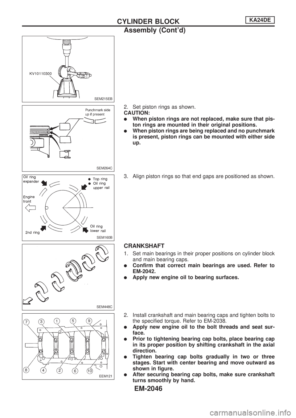
2. Set piston rings as shown.
CAUTION:
lWhen piston rings are not replaced, make sure that pis-
ton rings are mounted in their original positions.
lWhen piston rings are being replaced and no punchmark
is present, piston rings can be mounted with either side
up.
3. Align piston rings so that end gaps are positioned as shown.
CRANKSHAFT
1. Set main bearings in their proper positions on cylinder block
and main bearing caps.
lConfirm that correct main bearings are used. Refer to
EM-2042.
lApply new engine oil to bearing surfaces.
2. Install crankshaft and main bearing caps and tighten bolts to
the specified torque. Refer to EM-2038.
lApply new engine oil to the bolt threads and seat sur-
face.
lPrior to tightening bearing cap bolts, place bearing cap
in its proper position by shifting crankshaft in the axial
direction.
lTighten bearing cap bolts gradually in two or three
stages. Start with center bearing and move outward as
shown in figure.
lAfter securing bearing cap bolts, make sure crankshaft
turns smoothly by hand.
SEM215EB
SEM264C
SEM160B
SEM448C
EEM121
CYLINDER BLOCKKA24DE
Assembly (Cont'd)
EM-2046
Page 557 of 666
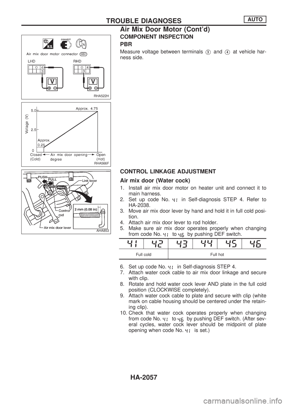
COMPONENT INSPECTION
PBR
Measure voltage between terminalsV3andV4at vehicle har-
ness side.
CONTROL LINKAGE ADJUSTMENT
Air mix door (Water cock)
1. Install air mix door motor on heater unit and connect it to
main harness.
2. Set up code No.
in Self-diagnosis STEP 4. Refer to
HA-2038.
3. Move air mix door lever by hand and hold it in full cold posi-
tion.
4. Attach air mix door lever to rod holder.
5. Make sure air mix door operates properly when changing
from code No.
toby pushing DEF switch.
Full cold Full hot
6. Set up code No.in Self-diagnosis STEP 4.
7. Attach water cock cable to air mix door linkage and secure
with clip.
8. Rotate and hold water cock lever AND plate in the full cold
position (CLOCKWISE completely).
9. Attach water cock cable to plate and secure with clip (white
mark on cable housing should be centered under the retain-
ing clip).
10. Check that water cock operates properly when changing
from code No.
toby pushing DEF switch. (After sev-
eral cycles, water cock lever should be midpoint of plate
opening when code No.
is set.)
RHA522H
RHA566F
AHA853
TROUBLE DIAGNOSESAUTO
Air Mix Door Motor (Cont'd)
HA-2057
Page 612 of 666
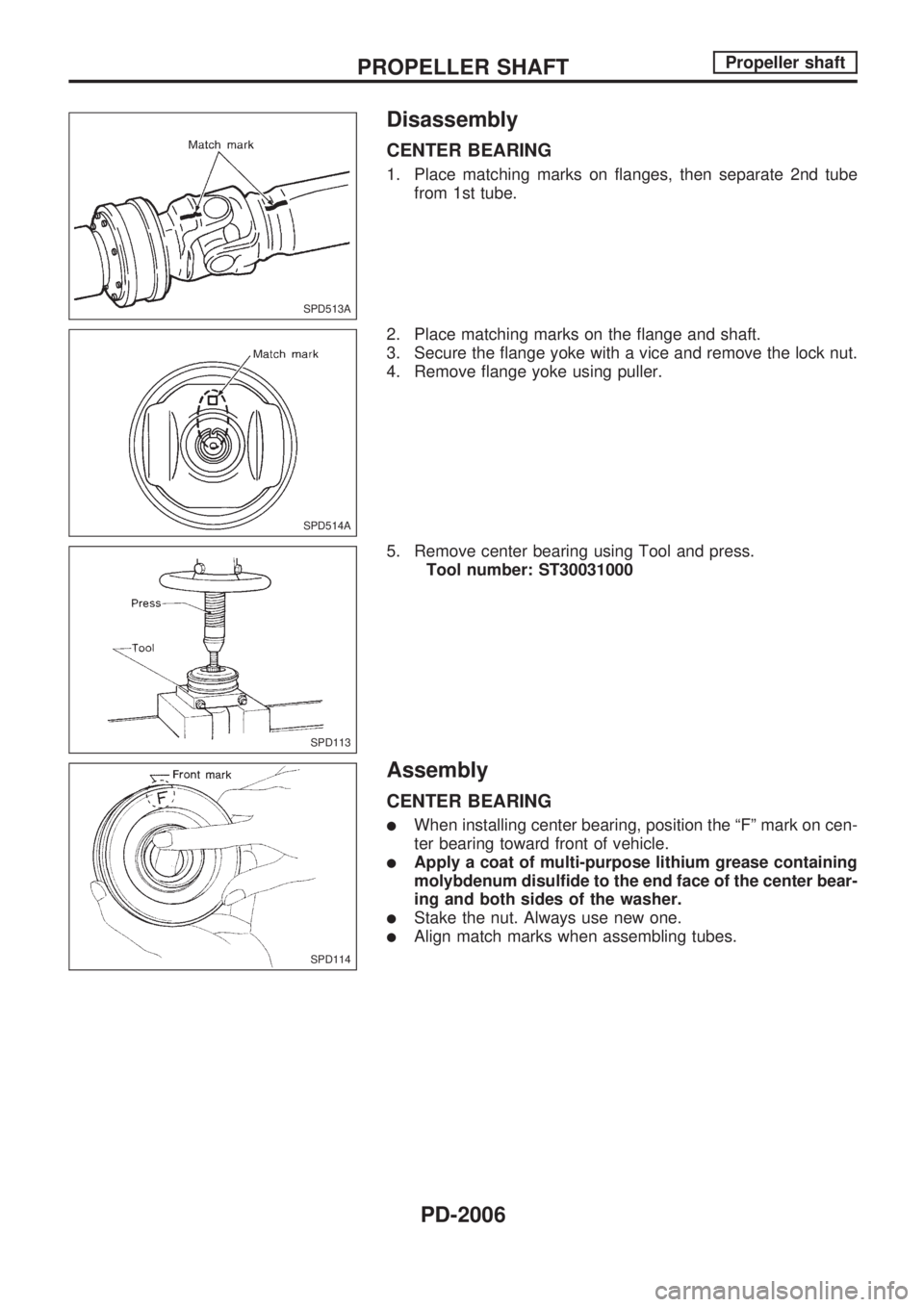
Disassembly
CENTER BEARING
1. Place matching marks on flanges, then separate 2nd tube
from 1st tube.
2. Place matching marks on the flange and shaft.
3. Secure the flange yoke with a vice and remove the lock nut.
4. Remove flange yoke using puller.
5. Remove center bearing using Tool and press.
Tool number: ST30031000
Assembly
CENTER BEARING
lWhen installing center bearing, position the ªFº mark on cen-
ter bearing toward front of vehicle.
lApply a coat of multi-purpose lithium grease containing
molybdenum disulfide to the end face of the center bear-
ing and both sides of the washer.
lStake the nut. Always use new one.
lAlign match marks when assembling tubes.
SPD513A
SPD514A
SPD113
SPD114
PROPELLER SHAFTPropeller shaft
PD-2006