display NISSAN PICK-UP 1999 Repair Manual
[x] Cancel search | Manufacturer: NISSAN, Model Year: 1999, Model line: PICK-UP, Model: NISSAN PICK-UP 1999Pages: 666, PDF Size: 16.21 MB
Page 525 of 666
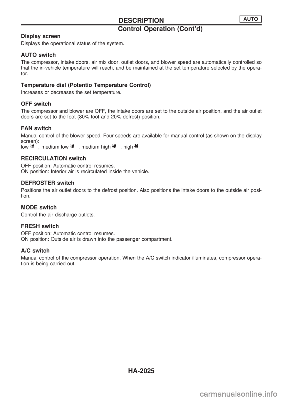
Display screen
Displays the operational status of the system.
AUTO switch
The compressor, intake doors, air mix door, outlet doors, and blower speed are automatically controlled so
that the in-vehicle temperature will reach, and be maintained at the set temperature selected by the opera-
tor.
Temperature dial (Potentio Temperature Control)
Increases or decreases the set temperature.
OFF switch
The compressor and blower are OFF, the intake doors are set to the outside air position, and the air outlet
doors are set to the foot (80% foot and 20% defrost) position.
FAN switch
Manual control of the blower speed. Four speeds are available for manual control (as shown on the display
screen):
low
, medium low, medium high, high
RECIRCULATION switch
OFF position: Automatic control resumes.
ON position: Interior air is recirculated inside the vehicle.
DEFROSTER switch
Positions the air outlet doors to the defrost position. Also positions the intake doors to the outside air posi-
tion.
MODE switch
Control the air discharge outlets.
FRESH switch
OFF position: Automatic control resumes.
ON position: Outside air is drawn into the passenger compartment.
A/C switch
Manual control of the compressor operation. When the A/C switch indicator illuminates, compressor opera-
tion is being carried out.
DESCRIPTIONAUTO
Control Operation (Cont'd)
HA-2025
Page 537 of 666

VB
STEP 3 - MODE DOOR POSITIONS
ARE CHECKED.
Does code No.
appear on the dis-
play?
YesNo
.
Turn temperature
dial clockwise.Mode door motor position switch is malfunctioning.
(If two or more mode doors are out of order, corre-
sponding code numbers blink respectively two
times.)
*1: If mode door motor harness connector is
disconnected, the following display pattern will
appear.
®
®®®®þ
VC
(Go to next page.)
Code
No.*1Mode door positionReference
page
VENT
HA-2049
B/L
FOOT
D/F
DEF
RHA869DC
RHA168DA
RHA498A
.
.
.
TROUBLE DIAGNOSESAUTO
Self-diagnosis (Cont'd)
HA-2037
Page 538 of 666
VC
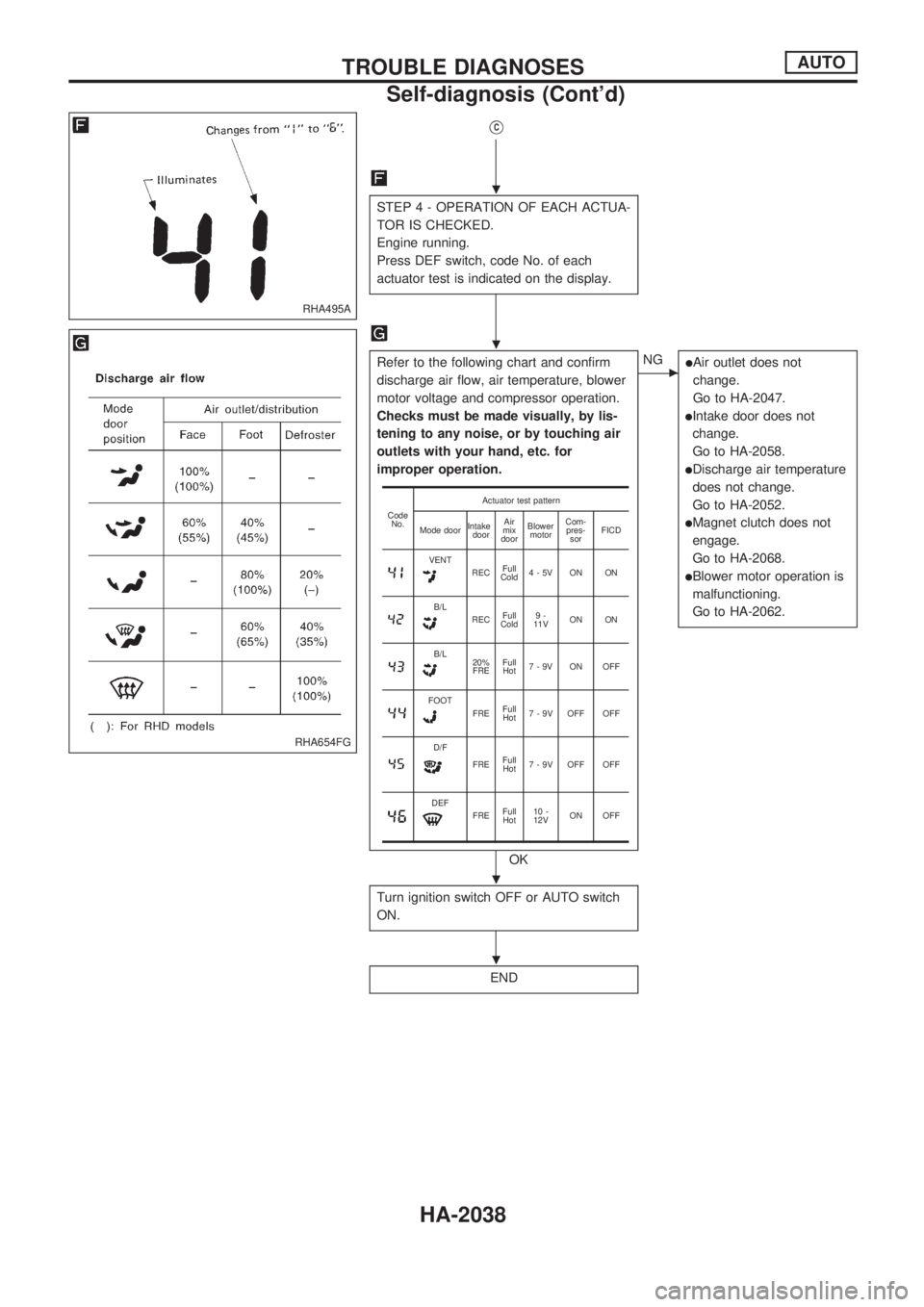
STEP 4 - OPERATION OF EACH ACTUA-
TOR IS CHECKED.
Engine running.
Press DEF switch, code No. of each
actuator test is indicated on the display.
Refer to the following chart and confirm
discharge air flow, air temperature, blower
motor voltage and compressor operation.
Checks must be made visually, by lis-
tening to any noise, or by touching air
outlets with your hand, etc. for
improper operation.
OK
cNGlAir outlet does not
change.
Go to HA-2047.
lIntake door does not
change.
Go to HA-2058.
lDischarge air temperature
does not change.
Go to HA-2052.
lMagnet clutch does not
engage.
Go to HA-2068.
lBlower motor operation is
malfunctioning.
Go to HA-2062.
Turn ignition switch OFF or AUTO switch
ON.
END
Code
No.Actuator test pattern
Mode doorIntake
doorAir
mix
doorBlower
motorCom-
pres-
sorFICD
VENTRECFull
Cold4-5V ON ON
B/LRECFull
Cold9-
11VON ON
B/L20%
FREFull
Hot7-9V ON OFF
FOOTFREFull
Hot7 - 9V OFF OFF
D/F
FREFull
Hot7 - 9V OFF OFF
DEFFREFull
Hot10 -
12VON OFF
RHA495A
RHA654FG
.
.
.
.
TROUBLE DIAGNOSESAUTO
Self-diagnosis (Cont'd)
HA-2038
Page 539 of 666
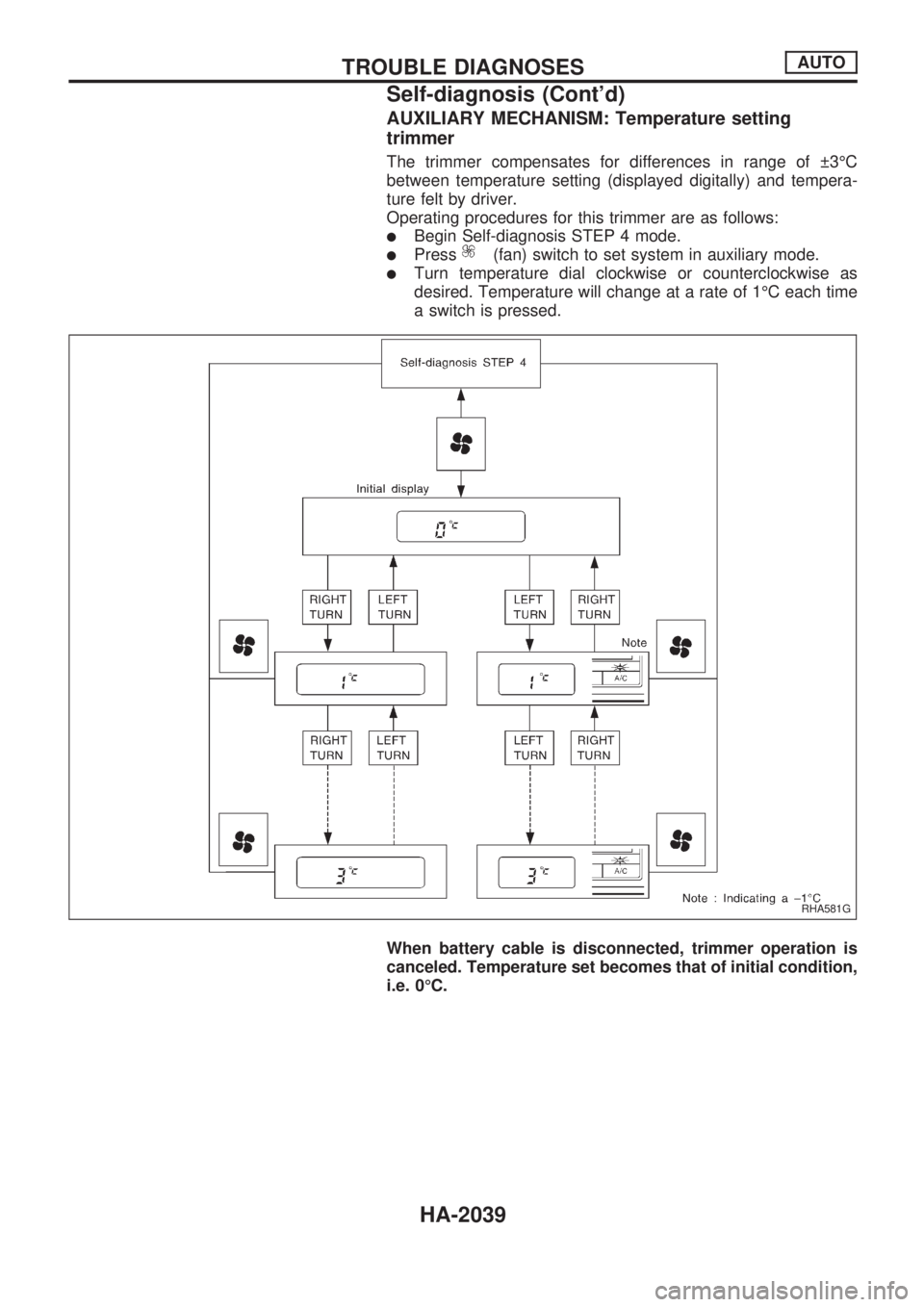
AUXILIARY MECHANISM: Temperature setting
trimmer
The trimmer compensates for differences in range of 3ÉC
between temperature setting (displayed digitally) and tempera-
ture felt by driver.
Operating procedures for this trimmer are as follows:
lBegin Self-diagnosis STEP 4 mode.
lPress(fan) switch to set system in auxiliary mode.
lTurn temperature dial clockwise or counterclockwise as
desired. Temperature will change at a rate of 1ÉC each time
a switch is pressed.
When battery cable is disconnected, trimmer operation is
canceled. Temperature set becomes that of initial condition,
i.e. 0ÉC.
RHA581G
TROUBLE DIAGNOSESAUTO
Self-diagnosis (Cont'd)
HA-2039
Page 543 of 666
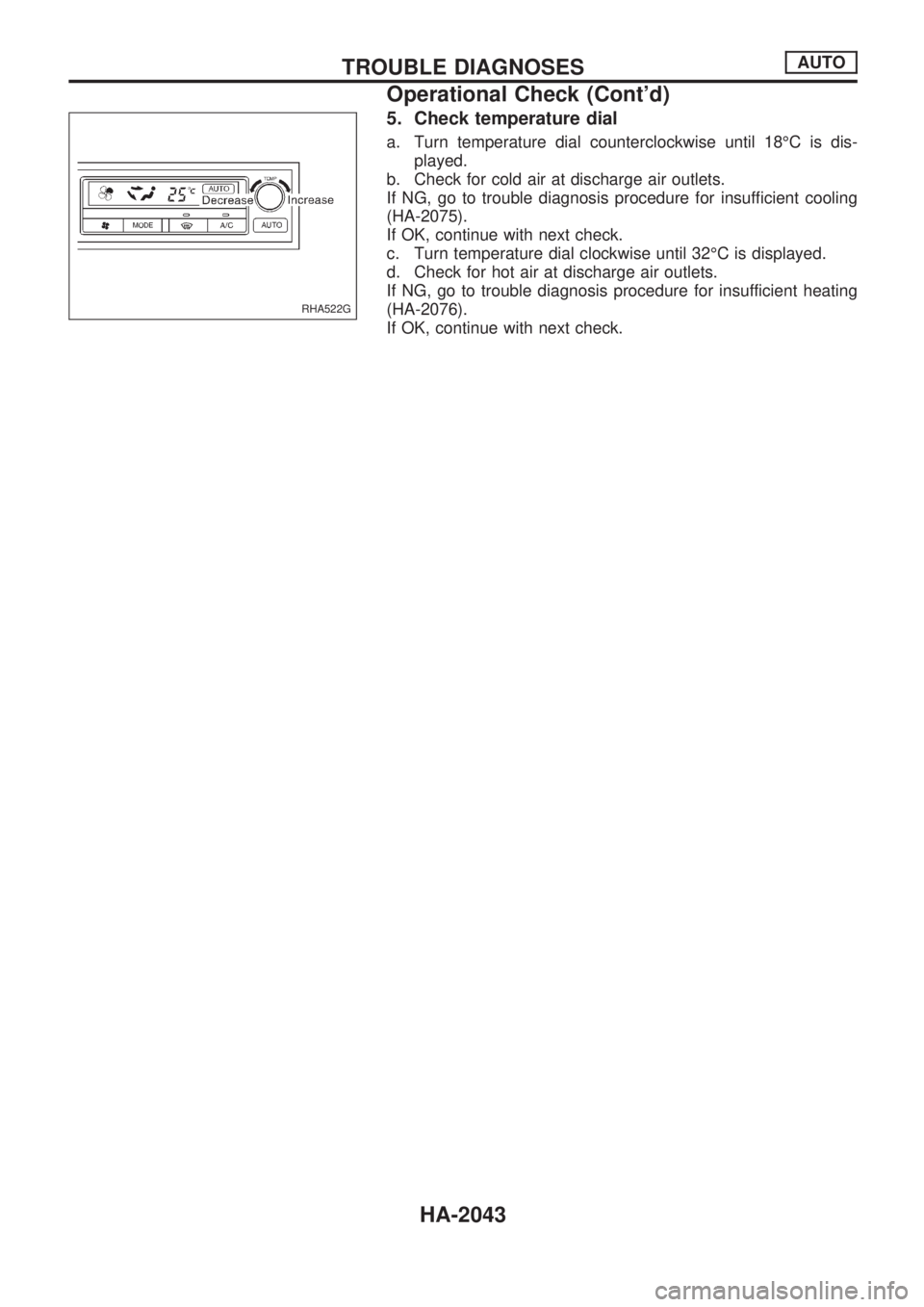
5. Check temperature dial
a. Turn temperature dial counterclockwise until 18ÉC is dis-
played.
b. Check for cold air at discharge air outlets.
If NG, go to trouble diagnosis procedure for insufficient cooling
(HA-2075).
If OK, continue with next check.
c. Turn temperature dial clockwise until 32ÉC is displayed.
d. Check for hot air at discharge air outlets.
If NG, go to trouble diagnosis procedure for insufficient heating
(HA-2076).
If OK, continue with next check.
RHA522G
TROUBLE DIAGNOSESAUTO
Operational Check (Cont'd)
HA-2043
Page 544 of 666
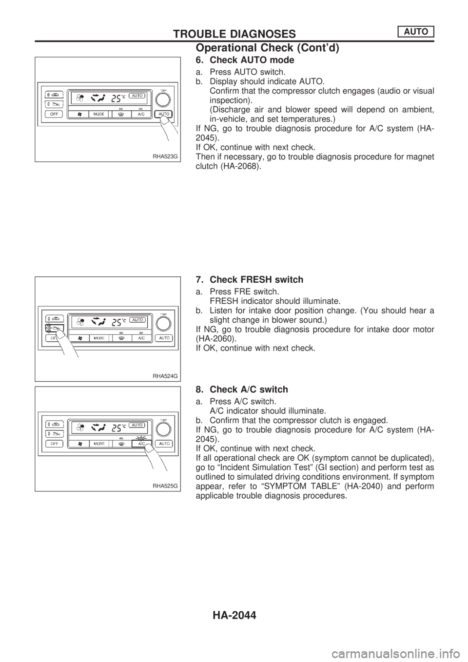
6. Check AUTO mode
a. Press AUTO switch.
b. Display should indicate AUTO.
Confirm that the compressor clutch engages (audio or visual
inspection).
(Discharge air and blower speed will depend on ambient,
in-vehicle, and set temperatures.)
If NG, go to trouble diagnosis procedure for A/C system (HA-
2045).
If OK, continue with next check.
Then if necessary, go to trouble diagnosis procedure for magnet
clutch (HA-2068).
7. Check FRESH switch
a. Press FRE switch.
FRESH indicator should illuminate.
b. Listen for intake door position change. (You should hear a
slight change in blower sound.)
If NG, go to trouble diagnosis procedure for intake door motor
(HA-2060).
If OK, continue with next check.
8. Check A/C switch
a. Press A/C switch.
A/C indicator should illuminate.
b. Confirm that the compressor clutch is engaged.
If NG, go to trouble diagnosis procedure for A/C system (HA-
2045).
If OK, continue with next check.
If all operational check are OK (symptom cannot be duplicated),
go to ªIncident Simulation Testº (GI section) and perform test as
outlined to simulated driving conditions environment. If symptom
appear, refer to ªSYMPTOM TABLEº (HA-2040) and perform
applicable trouble diagnosis procedures.
RHA523G
RHA524G
RHA525G
TROUBLE DIAGNOSESAUTO
Operational Check (Cont'd)
HA-2044
Page 545 of 666
A/C System
TROUBLE DIAGNOSIS PROCEDURE FOR A/C SYSTEM
SYMPTOM:
lA/C system does not come on.
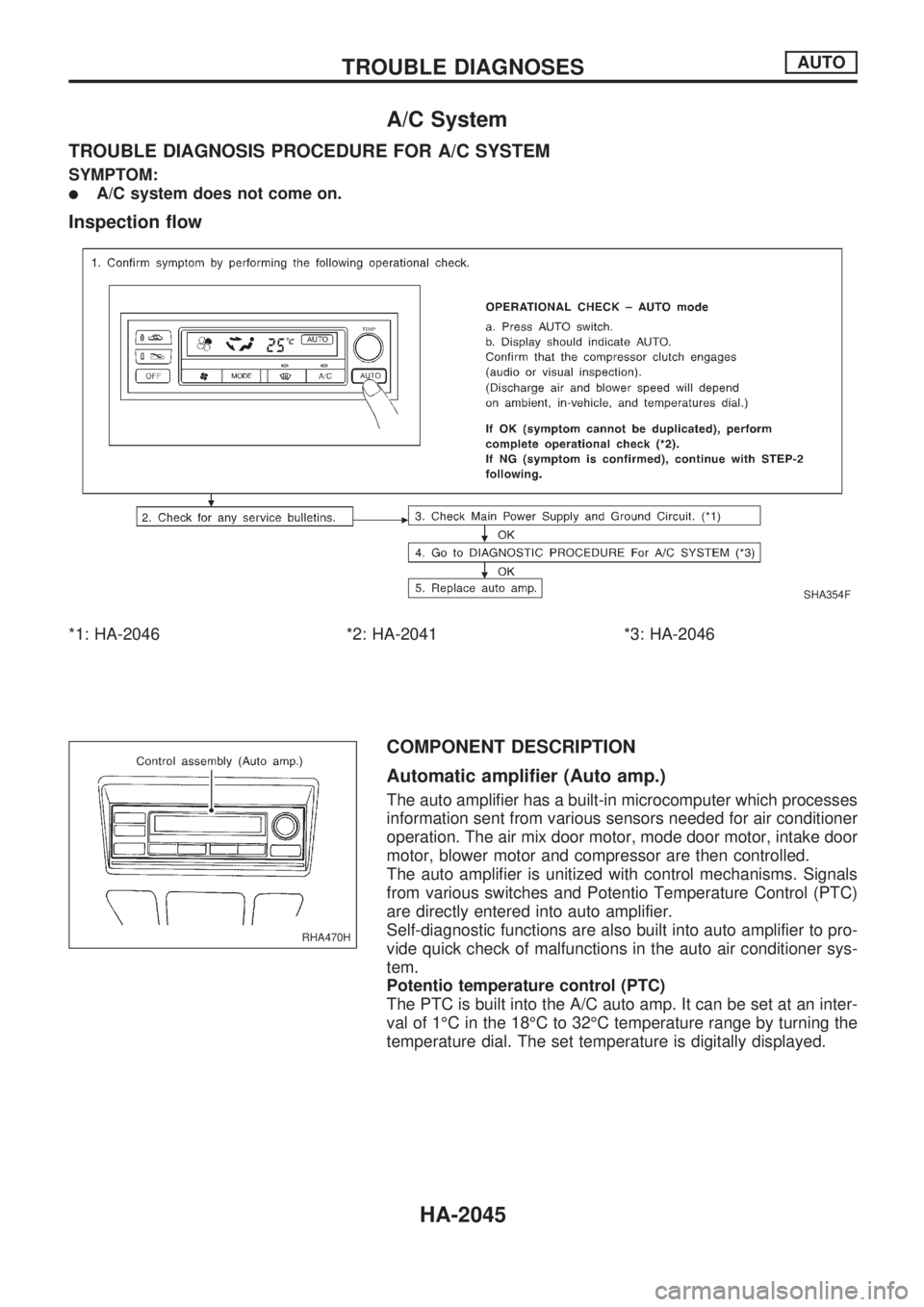
Inspection flow
*1: HA-2046 *2: HA-2041 *3: HA-2046
COMPONENT DESCRIPTION
Automatic amplifier (Auto amp.)
The auto amplifier has a built-in microcomputer which processes
information sent from various sensors needed for air conditioner
operation. The air mix door motor, mode door motor, intake door
motor, blower motor and compressor are then controlled.
The auto amplifier is unitized with control mechanisms. Signals
from various switches and Potentio Temperature Control (PTC)
are directly entered into auto amplifier.
Self-diagnostic functions are also built into auto amplifier to pro-
vide quick check of malfunctions in the auto air conditioner sys-
tem.
Potentio temperature control (PTC)
The PTC is built into the A/C auto amp. It can be set at an inter-
val of 1ÉC in the 18ÉC to 32ÉC temperature range by turning the
temperature dial. The set temperature is digitally displayed.
SHA354F
RHA470H
TROUBLE DIAGNOSESAUTO
HA-2045
Page 637 of 666
Trouble Diagnoses Introduction
CAUTION:
lDo not use electrical test equipment to check SRS harness connectors unless instructed to in
this Service Manual. SRS wiring harnesses can be identified by yellow harness protector or yel-
low insulation tape before the harness connectors.
lDo not attempt to repair, splice or modify the SRS wiring harness. If the harness is damaged,
replace it with a new one.
lKeep ground portion clean.
DIAGNOSIS FUNCTION
The SRS self-diagnosis results can be read by using ``AIR BAG'' warning lamp and/or CONSULT. The
reading of these results is accomplished using one of two modes Ð ``User mode'' and ``Diagnosis mode''.
The User mode is exclusively prepared for the customer (driver). This mode warns the driver of a system
malfunction through the operation of the ``AIR BAG'' warning lamp.
The Diagnosis mode allows the technician to locate and inspect the malfunctioning part.
The mode applications for the ``AIR BAG'' warning lamp and CONSULT are as follows:
User mode Diagnosis mode Display type
``AIR BAG'' warning lamp X X ON-OFF operation
DIAGNOSIS MODE FOR CONSULT
l``SELF-DIAG [CURRENT]''
A current Self-diagnosis result (also indicated by the warning lamp flashes in the Diagnosis mode) is
displayed on the CONSULT screen in real time. This refers to a malfunctioning part requiring repairs.
l``SELF-DIAG [PAST]''
Diagnosis results previously stored in the memory are displayed on the CONSULT screen. The stored
results are not erased until memory erasing is executed.
l``TROUBLE DIAG RECORD''
With TROUBLE DIAG RECORD, diagnosis results previously erased by a reset operation can be dis-
played on the CONSULT screen.
l``ECU DISCRIMINATED NO.''
The diagnosis sensor unit for each vehicle model is assigned with its own, individual classification number.
This number will be displayed on the CONSULT screen, as shown at left. When replacing the diagnosis
sensor unit, refer to the part number for the compatibility. After installation, replacement with a correct unit
can be checked by confirming this classification number on the CONSULT screen. The diagnosis sensor
unit classification number varies depending on SRS configuration.
For NISSAN MODEL D22, the diagnosis sensor unit classification numbers assigned are as follows.
MODEL ECU DISCRIMINATED NO.
Single air bag 5A0B
Dual air bag 5A0A
TROUBLE DIAGNOSES Ð Supplemental Restraint System (SRS)
RS-2015
Page 639 of 666
![NISSAN PICK-UP 1999 Repair Manual HOW TO ERASE SELF-DIAGNOSIS RESULTS
With CONSULT
l``SELF-DIAG [CURRENT]
A current Self-diagnosis result is displayed on the CONSULT screen in real time. After the malfunction
is repaired completely, NISSAN PICK-UP 1999 Repair Manual HOW TO ERASE SELF-DIAGNOSIS RESULTS
With CONSULT
l``SELF-DIAG [CURRENT]
A current Self-diagnosis result is displayed on the CONSULT screen in real time. After the malfunction
is repaired completely,](/img/5/57373/w960_57373-638.png)
HOW TO ERASE SELF-DIAGNOSIS RESULTS
With CONSULT
l``SELF-DIAG [CURRENT]''
A current Self-diagnosis result is displayed on the CONSULT screen in real time. After the malfunction
is repaired completely, no malfunction is detected on ``SELF-DIAG [CURRENT]''.
l``SELF-DIAG [PAST]''
Return to the ``SELF-DIAG [CURRENT]'' CONSULT screen
by pushing ``BACK'' key of CONSULT and select ``SELF-
DIAG [CURRENT]'' in ``SELECT DIAG MODE''. Touch
``ERASE'' in ``SELF-DIAG [CURRENT]'' mode.
NOTE:
If the memory of the malfunction in ``SELF-DIAG [PAST]'' is
not erased, the User mode shows the system malfunction by
the operation of the warning lamp even if the malfunction is
repaired completely.
l``TROUBLE DIAG RECORD''
The memory of ``TROUBLE DIAG RECORD'' cannot be erased.
Without CONSULT
After a malfunction is repaired, return Diagnosis mode to User mode by switching the ignition ``OFF'' for at
least 1 second, then back ``ON''. At that time, the self-diagnostic result is cleared.
How to Perform Trouble Diagnoses for Quick
and Accurate Repair
A good understanding of the malfunction conditions can make troubleshooting faster and more accurate.
In general, each customer feels differently about a malfunction. It is important to fully understand the symp-
toms or conditions for a customer complaint.
INFORMATION FROM CUSTOMER
WHAT ........ Vehicle model
WHEN ....... Date, Frequencies
WHERE ..... Road conditions
HOW .......... Operating conditions, Symptoms
PRELIMINARY CHECK
Check that the following parts are in good order.
lBattery [Refer to EL section (``BATTERY'') of Service Manual.]
lFuse [Refer to EL section (``Fuse'', ``POWER SUPPLY ROUTING'') of Service Manual.]
lSystem component-to-harness connections
SRS357
TROUBLE DIAGNOSES Ð Supplemental Restraint System (SRS)
Trouble Diagnoses Introduction (Cont'd)
RS-2017
Page 648 of 666
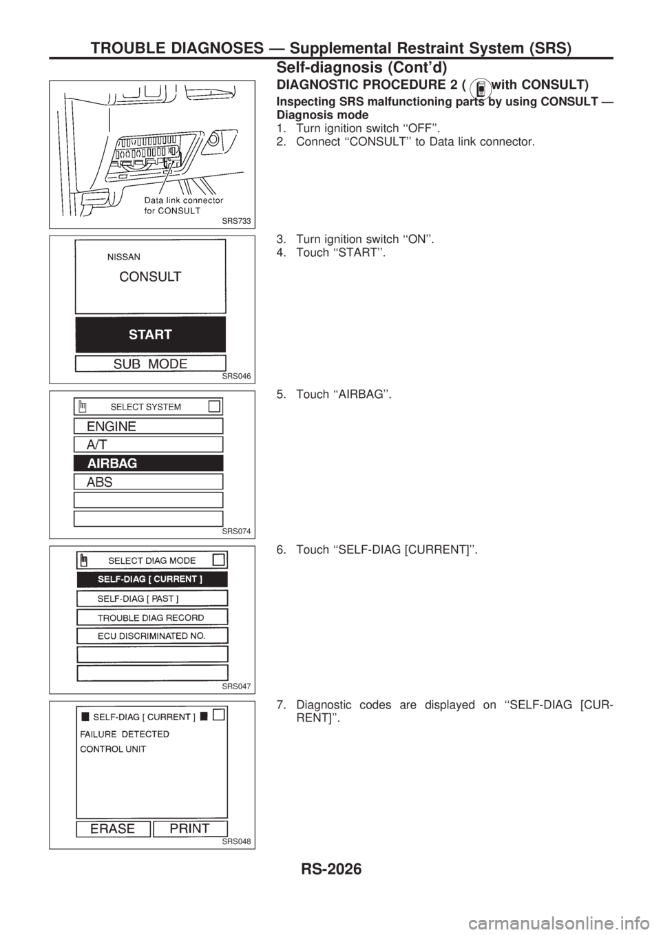
DIAGNOSTIC PROCEDURE 2 (with CONSULT)
Inspecting SRS malfunctioning parts by using CONSULT Ð
Diagnosis mode
1. Turn ignition switch ``OFF''.
2. Connect ``CONSULT'' to Data link connector.
3. Turn ignition switch ``ON''.
4. Touch ``START''.
5. Touch ``AIRBAG''.
6. Touch ``SELF-DIAG [CURRENT]''.
7. Diagnostic codes are displayed on ``SELF-DIAG [CUR-
RENT]''.
SRS733
SRS046
SRS074
SRS047
SRS048
TROUBLE DIAGNOSES Ð Supplemental Restraint System (SRS)
Self-diagnosis (Cont'd)
RS-2026