key battery NISSAN PICK-UP 1999 Repair Manual
[x] Cancel search | Manufacturer: NISSAN, Model Year: 1999, Model line: PICK-UP, Model: NISSAN PICK-UP 1999Pages: 666, PDF Size: 16.21 MB
Page 214 of 666
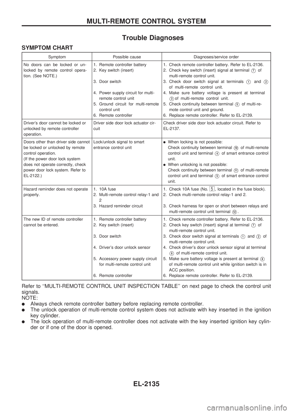
Trouble Diagnoses
SYMPTOM CHART
Symptom Possible cause Diagnoses/service order
No doors can be locked or un-
locked by remote control opera-
tion. (See NOTE.)1. Remote controller battery
2. Key switch (insert)
3. Door switch
4. Power supply circuit for multi-
remote control unit
5. Ground circuit for multi-remote
control unit
6. Remote controller1. Check remote controller battery. Refer to EL-2136.
2. Check key switch (insert) signal at terminal
V7of
multi-remote control unit.
3. Check door switch signal at terminals
V1andV2
of multi-remote control unit.
4. Make sure battery voltage is present at terminal
V3of multi-remote control unit.
5. Check continuity between terminal
V5of multi-re-
mote control unit and ground.
6. Replace remote controller. Refer to EL-2139.
Driver's door cannot be locked or
unlocked by remote controller
operation.Driver side door lock actuator cir-
cuitCheck driver side door lock actuator circuit. Refer to
EL-2137.
Doors other than driver side cannot
be locked or unlocked by remote
control operation.
(If the power door lock system
does not operate correctly, check
power door lock system. Refer to
EL-2122.)Lock/unlock signal to smart
entrance control unit
lWhen locking is not possible:
Check continuity between terminal
V10of multi-remote
control unit and terminal
V4of smart entrance control
unit.
lWhen unlocking is not possible:
Check continuity between terminal
V11of multi-remote
control unit and terminal
V5of smart entrance control
unit.
Hazard reminder does not operate
properly.1. 10A fuse
2. Multi-remote control relay-1 and
2
3. Hazard reminder circuit1. Check 10A fuse (No.
5, located in the fuse block).
2. Check multi-remote control relay-1 and 2.
3. Check harness for open or short between relays and
multi-remote control unit terminal
V12.
The new ID of remote controller
cannot be entered.1. Remote controller battery
2. Key switch (insert)
3. Door switch
4. Driver's door unlock sensor
5. Accessory power supply circuit
for multi-remote control unit
6. Remote controller1. Check remote controller battery. Refer to EL-2136.
2. Check key switch (insert) signal at terminal
V7of
multi-remote control unit.
3. Check door switch signal at terminals
V1andV2of
multi-remote control unit.
4. Check driver's door unlock sensor signal at terminal
V6of multi-remote control unit.
5. Make sure battery voltage is present at terminal
V8
of multi-remote control unit while ignition switch is in
ACC position.
6. Replace remote controller. Refer to EL-2139.
Refer to ``MULTI-REMOTE CONTROL UNIT INSPECTION TABLE'' on next page to check the control unit
signals.
NOTE:
lAlways check remote controller battery before replacing remote controller.
lThe unlock operation of multi-remote control system does not activate with key inserted in the ignition
key cylinder.
lThe lock operation of multi-remote controller does not activate with the key inserted ignition key cylin-
der or if one of the door is opened.
MULTI-REMOTE CONTROL SYSTEM
EL-2135
Page 215 of 666
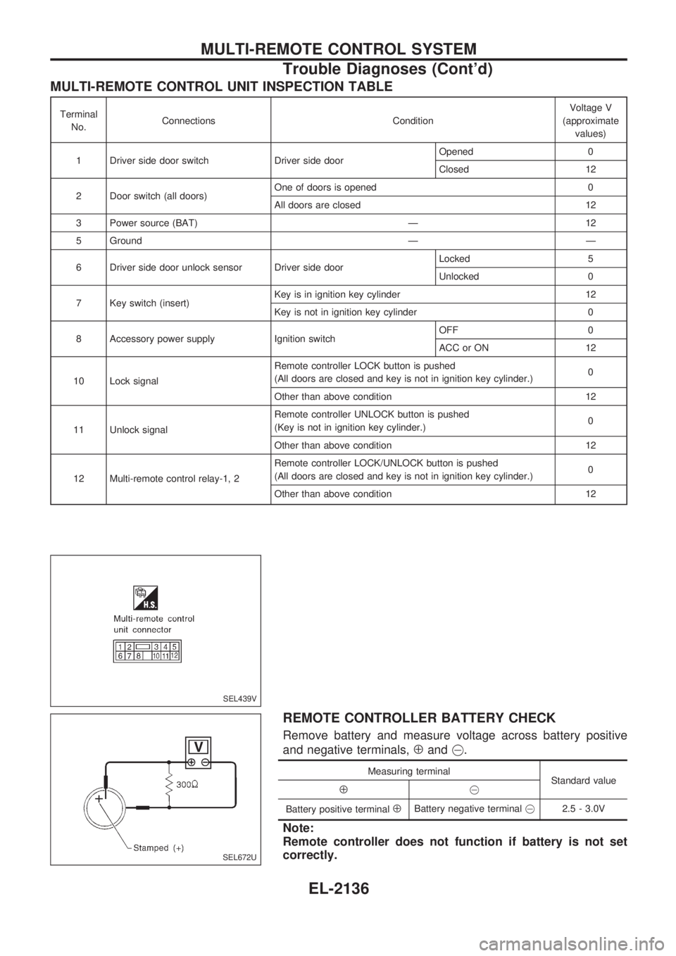
MULTI-REMOTE CONTROL UNIT INSPECTION TABLE
Terminal
No.Connections ConditionVoltage V
(approximate
values)
1 Driver side door switch Driver side doorOpened 0
Closed 12
2 Door switch (all doors)One of doors is opened 0
All doors are closed 12
3 Power source (BAT) Ð 12
5 Ground Ð Ð
6 Driver side door unlock sensor Driver side doorLocked 5
Unlocked 0
7 Key switch (insert)Key is in ignition key cylinder 12
Key is not in ignition key cylinder 0
8 Accessory power supply Ignition switchOFF 0
ACC or ON 12
10 Lock signalRemote controller LOCK button is pushed
(All doors are closed and key is not in ignition key cylinder.)0
Other than above condition 12
11 Unlock signalRemote controller UNLOCK button is pushed
(Key is not in ignition key cylinder.)0
Other than above condition 12
12 Multi-remote control relay-1, 2Remote controller LOCK/UNLOCK button is pushed
(All doors are closed and key is not in ignition key cylinder.)0
Other than above condition 12
REMOTE CONTROLLER BATTERY CHECK
Remove battery and measure voltage across battery positive
and negative terminals,
Åand@.
Measuring terminal
Standard value
Å@
Battery positive terminal
ÅBattery negative [email protected] - 3.0V
Note:
Remote controller does not function if battery is not set
correctly.
SEL439V
SEL672U
MULTI-REMOTE CONTROL SYSTEM
Trouble Diagnoses (Cont'd)
EL-2136
Page 386 of 666
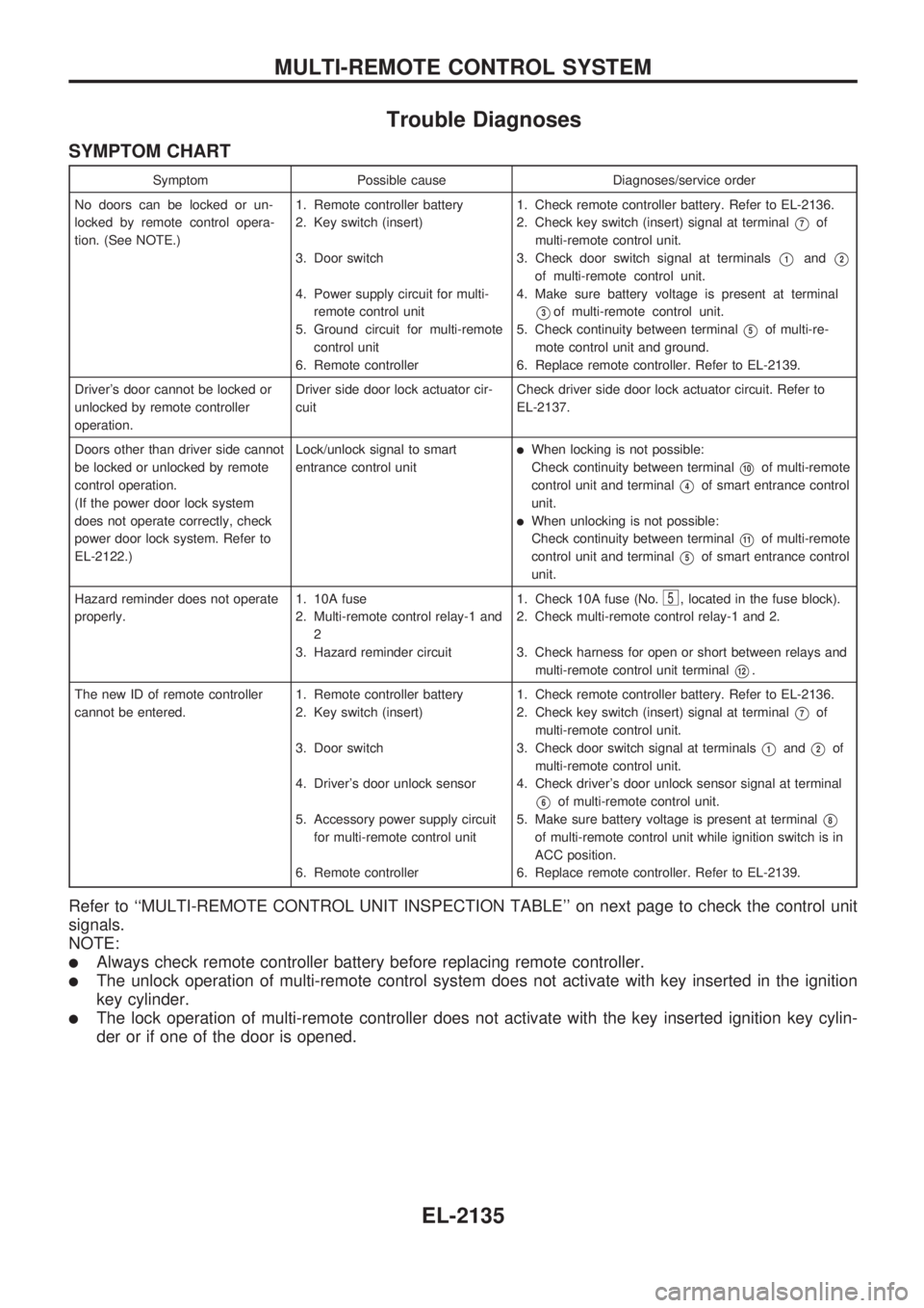
Trouble Diagnoses
SYMPTOM CHART
Symptom Possible cause Diagnoses/service order
No doors can be locked or un-
locked by remote control opera-
tion. (See NOTE.)1. Remote controller battery
2. Key switch (insert)
3. Door switch
4. Power supply circuit for multi-
remote control unit
5. Ground circuit for multi-remote
control unit
6. Remote controller1. Check remote controller battery. Refer to EL-2136.
2. Check key switch (insert) signal at terminal
V7of
multi-remote control unit.
3. Check door switch signal at terminals
V1andV2
of multi-remote control unit.
4. Make sure battery voltage is present at terminal
V3of multi-remote control unit.
5. Check continuity between terminal
V5of multi-re-
mote control unit and ground.
6. Replace remote controller. Refer to EL-2139.
Driver's door cannot be locked or
unlocked by remote controller
operation.Driver side door lock actuator cir-
cuitCheck driver side door lock actuator circuit. Refer to
EL-2137.
Doors other than driver side cannot
be locked or unlocked by remote
control operation.
(If the power door lock system
does not operate correctly, check
power door lock system. Refer to
EL-2122.)Lock/unlock signal to smart
entrance control unit
lWhen locking is not possible:
Check continuity between terminal
V10of multi-remote
control unit and terminal
V4of smart entrance control
unit.
lWhen unlocking is not possible:
Check continuity between terminal
V11of multi-remote
control unit and terminal
V5of smart entrance control
unit.
Hazard reminder does not operate
properly.1. 10A fuse
2. Multi-remote control relay-1 and
2
3. Hazard reminder circuit1. Check 10A fuse (No.
5, located in the fuse block).
2. Check multi-remote control relay-1 and 2.
3. Check harness for open or short between relays and
multi-remote control unit terminal
V12.
The new ID of remote controller
cannot be entered.1. Remote controller battery
2. Key switch (insert)
3. Door switch
4. Driver's door unlock sensor
5. Accessory power supply circuit
for multi-remote control unit
6. Remote controller1. Check remote controller battery. Refer to EL-2136.
2. Check key switch (insert) signal at terminal
V7of
multi-remote control unit.
3. Check door switch signal at terminals
V1andV2of
multi-remote control unit.
4. Check driver's door unlock sensor signal at terminal
V6of multi-remote control unit.
5. Make sure battery voltage is present at terminal
V8
of multi-remote control unit while ignition switch is in
ACC position.
6. Replace remote controller. Refer to EL-2139.
Refer to ``MULTI-REMOTE CONTROL UNIT INSPECTION TABLE'' on next page to check the control unit
signals.
NOTE:
lAlways check remote controller battery before replacing remote controller.
lThe unlock operation of multi-remote control system does not activate with key inserted in the ignition
key cylinder.
lThe lock operation of multi-remote controller does not activate with the key inserted ignition key cylin-
der or if one of the door is opened.
MULTI-REMOTE CONTROL SYSTEM
EL-2135
Page 387 of 666
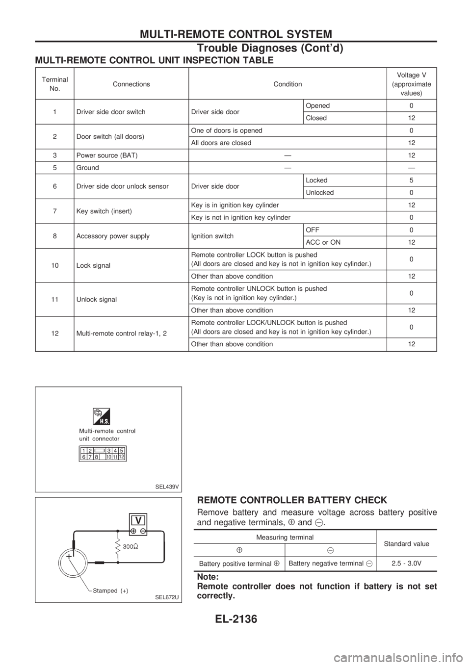
MULTI-REMOTE CONTROL UNIT INSPECTION TABLE
Terminal
No.Connections ConditionVoltage V
(approximate
values)
1 Driver side door switch Driver side doorOpened 0
Closed 12
2 Door switch (all doors)One of doors is opened 0
All doors are closed 12
3 Power source (BAT) Ð 12
5 Ground Ð Ð
6 Driver side door unlock sensor Driver side doorLocked 5
Unlocked 0
7 Key switch (insert)Key is in ignition key cylinder 12
Key is not in ignition key cylinder 0
8 Accessory power supply Ignition switchOFF 0
ACC or ON 12
10 Lock signalRemote controller LOCK button is pushed
(All doors are closed and key is not in ignition key cylinder.)0
Other than above condition 12
11 Unlock signalRemote controller UNLOCK button is pushed
(Key is not in ignition key cylinder.)0
Other than above condition 12
12 Multi-remote control relay-1, 2Remote controller LOCK/UNLOCK button is pushed
(All doors are closed and key is not in ignition key cylinder.)0
Other than above condition 12
REMOTE CONTROLLER BATTERY CHECK
Remove battery and measure voltage across battery positive
and negative terminals,
Åand@.
Measuring terminal
Standard value
Å@
Battery positive terminal
ÅBattery negative [email protected] - 3.0V
Note:
Remote controller does not function if battery is not set
correctly.
SEL439V
SEL672U
MULTI-REMOTE CONTROL SYSTEM
Trouble Diagnoses (Cont'd)
EL-2136
Page 639 of 666
![NISSAN PICK-UP 1999 Repair Manual HOW TO ERASE SELF-DIAGNOSIS RESULTS
With CONSULT
l``SELF-DIAG [CURRENT]
A current Self-diagnosis result is displayed on the CONSULT screen in real time. After the malfunction
is repaired completely,](/img/5/57373/w960_57373-638.png "NISSAN PICK-UP 1999 Repair Manual HOW TO ERASE SELF-DIAGNOSIS RESULTS
With CONSULT
l``SELF-DIAG [CURRENT]
A current Self-diagnosis result is displayed on the CONSULT screen in real time. After the malfunction
is repaired completely,")
HOW TO ERASE SELF-DIAGNOSIS RESULTS
With CONSULT
l``SELF-DIAG [CURRENT]''
A current Self-diagnosis result is displayed on the CONSULT screen in real time. After the malfunction
is repaired completely, no malfunction is detected on ``SELF-DIAG [CURRENT]''.
l``SELF-DIAG [PAST]''
Return to the ``SELF-DIAG [CURRENT]'' CONSULT screen
by pushing ``BACK'' key of CONSULT and select ``SELF-
DIAG [CURRENT]'' in ``SELECT DIAG MODE''. Touch
``ERASE'' in ``SELF-DIAG [CURRENT]'' mode.
NOTE:
If the memory of the malfunction in ``SELF-DIAG [PAST]'' is
not erased, the User mode shows the system malfunction by
the operation of the warning lamp even if the malfunction is
repaired completely.
l``TROUBLE DIAG RECORD''
The memory of ``TROUBLE DIAG RECORD'' cannot be erased.
Without CONSULT
After a malfunction is repaired, return Diagnosis mode to User mode by switching the ignition ``OFF'' for at
least 1 second, then back ``ON''. At that time, the self-diagnostic result is cleared.
How to Perform Trouble Diagnoses for Quick
and Accurate Repair
A good understanding of the malfunction conditions can make troubleshooting faster and more accurate.
In general, each customer feels differently about a malfunction. It is important to fully understand the symp-
toms or conditions for a customer complaint.
INFORMATION FROM CUSTOMER
WHAT ........ Vehicle model
WHEN ....... Date, Frequencies
WHERE ..... Road conditions
HOW .......... Operating conditions, Symptoms
PRELIMINARY CHECK
Check that the following parts are in good order.
lBattery [Refer to EL section (``BATTERY'') of Service Manual.]
lFuse [Refer to EL section (``Fuse'', ``POWER SUPPLY ROUTING'') of Service Manual.]
lSystem component-to-harness connections
SRS357
TROUBLE DIAGNOSES Ð Supplemental Restraint System (SRS)
Trouble Diagnoses Introduction (Cont'd)
RS-2017
Page 649 of 666
![NISSAN PICK-UP 1999 Repair Manual If no malfunction is detected on ``SELF-DIAG [CURRENT] even
though malfunction is detected by the ``AIR BAG warning lamp,
check the battery voltage.
If the battery voltage is less than 9V, charge](/img/5/57373/w960_57373-648.png "NISSAN PICK-UP 1999 Repair Manual If no malfunction is detected on ``SELF-DIAG [CURRENT] even
though malfunction is detected by the ``AIR BAG warning lamp,
check the battery voltage.
If the battery voltage is less than 9V, charge")
If no malfunction is detected on ``SELF-DIAG [CURRENT]'' even
though malfunction is detected by the ``AIR BAG'' warning lamp,
check the battery voltage.
If the battery voltage is less than 9V, charge the battery. Then
go to DIAGNOSTIC PROCEDURE 4 for final checking, page
RS-2030.
If the battery voltage is OK, go to DIAGNOSTIC PROCEDURE
6, page RS-2034, to diagnose the following situations:
lSelf-diagnostic result (previously stored in the memory)
might not be erased after repair.
lThe SRS system malfunctions intermittently.
8. Touch ``PRINT''.
9. Compare diagnostic codes to the CONSULT DIAGNOSTIC
CODE CHART, page RS-2028.
10. Touch ``BACK'' key of CONSULT until ``SELECT SYSTEM''
appears in order to return to User mode from Diagnosis
mode, then turn off CONSULT.
11. Turn ignition switch ``OFF'', then disconnect CONSULT and
both battery cables.
12. Repair the system as outlined by the ``Repair order'' in CON-
SULT DIAGNOSTIC CODE CHART, that corresponds to the
self-diagnostic result. For replacement procedure of compo-
nent parts, refer to RS-2007.
13. After repairing the system, go to DIAGNOSTIC PROCE-
DURE 4 for final checking, page RS-2030.SRS049
TROUBLE DIAGNOSES Ð Supplemental Restraint System (SRS)
Self-diagnosis (Cont'd)
RS-2027
Page 654 of 666
![NISSAN PICK-UP 1999 Repair Manual 10. Check that no malfunction is detected on ``SELF-DIAG
[PAST].
11. Touch ``BACK key of CONSULT until SELECT SYSTEM
appears, turn off CONSULT, then disconnect CONSULT.
12. Turn ignition switch ``](/img/5/57373/w960_57373-653.png "NISSAN PICK-UP 1999 Repair Manual 10. Check that no malfunction is detected on ``SELF-DIAG
[PAST].
11. Touch ``BACK key of CONSULT until SELECT SYSTEM
appears, turn off CONSULT, then disconnect CONSULT.
12. Turn ignition switch ``")
10. Check that no malfunction is detected on ``SELF-DIAG
[PAST]''.
11. Touch ``BACK'' key of CONSULT until SELECT SYSTEM
appears, turn off CONSULT, then disconnect CONSULT.
12. Turn ignition switch ``OFF''.
13. Go to DIAGNOSTIC PROCEDURE 1, page RS-2025 to
check SRS operation by using ``AIR BAG'' warning lamp with
User mode.
DIAGNOSTIC PROCEDURE 5 (without CONSULT)
Final checking after repairing SRS by using ``AIR BAG''
warning lamp Ð Diagnosis mode and User mode
1. After repairing SRS connect both battery cables.
2. Open driver's door.
3. Turn ignition switch from ``OFF'' to ``ON''.
4. ``AIR BAG'' warning lamp operates in Diagnosis mode as
follows:
No. ``AIR BAG'' warning lamp flash pattern Ð Diagnosis mode Ð SRS condition
1
SRS333
V0athroughV0bare repeated. No malfunc-
tion is
detected or
repair is com-
pleted.
No further
action is nec-
essary.
2
SRS341
V0athroughV0dare repeated.
V0bÐ Driver and passenger air
bag marker (For identifying
driver and/or passenger air
bag malfunctioning)
V0dÐ Indicates malfunctioning
part. The number of
flashes varies with mal-
functioning part (0.5 sec.
ON and 0.5 sec. OFF is
counted as one flash.)The system is
malfunctioning
and needs to
be repaired.
SRS062
SRS170
TROUBLE DIAGNOSES Ð Supplemental Restraint System (SRS)
Self-diagnosis (Cont'd)
RS-2032
Page 658 of 666
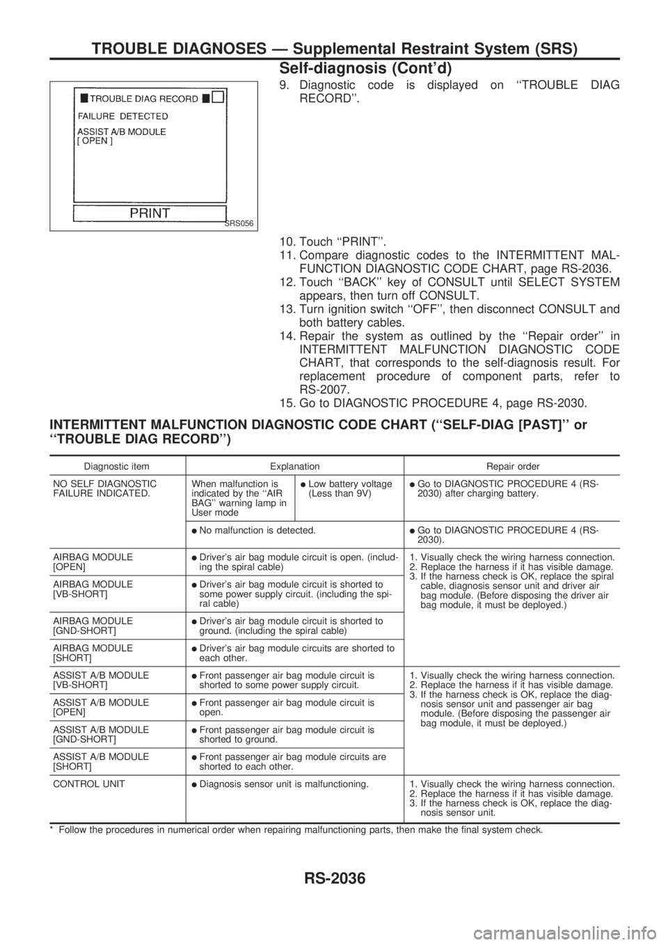
9. Diagnostic code is displayed on ``TROUBLE DIAG
RECORD''.
10. Touch ``PRINT''.
11. Compare diagnostic codes to the INTERMITTENT MAL-
FUNCTION DIAGNOSTIC CODE CHART, page RS-2036.
12. Touch ``BACK'' key of CONSULT until SELECT SYSTEM
appears, then turn off CONSULT.
13. Turn ignition switch ``OFF'', then disconnect CONSULT and
both battery cables.
14. Repair the system as outlined by the ``Repair order'' in
INTERMITTENT MALFUNCTION DIAGNOSTIC CODE
CHART, that corresponds to the self-diagnosis result. For
replacement procedure of component parts, refer to
RS-2007.
15. Go to DIAGNOSTIC PROCEDURE 4, page RS-2030.
INTERMITTENT MALFUNCTION DIAGNOSTIC CODE CHART (``SELF-DIAG [PAST]'' or
``TROUBLE DIAG RECORD'')
Diagnostic item Explanation Repair order
NO SELF DIAGNOSTIC
FAILURE INDICATED.When malfunction is
indicated by the ``AIR
BAG'' warning lamp in
User mode
lLow battery voltage
(Less than 9V)lGo to DIAGNOSTIC PROCEDURE 4 (RS-
2030) after charging battery.
lNo malfunction is detected.lGo to DIAGNOSTIC PROCEDURE 4 (RS-
2030).
AIRBAG MODULE
[OPEN]
lDriver's air bag module circuit is open. (includ-
ing the spiral cable)1. Visually check the wiring harness connection.
2. Replace the harness if it has visible damage.
3. If the harness check is OK, replace the spiral
cable, diagnosis sensor unit and driver air
bag module. (Before disposing the driver air
bag module, it must be deployed.) AIRBAG MODULE
[VB-SHORT]
lDriver's air bag module circuit is shorted to
some power supply circuit. (including the spi-
ral cable)
AIRBAG MODULE
[GND-SHORT]
lDriver's air bag module circuit is shorted to
ground. (including the spiral cable)
AIRBAG MODULE
[SHORT]
lDriver's air bag module circuits are shorted to
each other.
ASSIST A/B MODULE
[VB-SHORT]
lFront passenger air bag module circuit is
shorted to some power supply circuit.1. Visually check the wiring harness connection.
2. Replace the harness if it has visible damage.
3. If the harness check is OK, replace the diag-
nosis sensor unit and passenger air bag
module. (Before disposing the passenger air
bag module, it must be deployed.) ASSIST A/B MODULE
[OPEN]
lFront passenger air bag module circuit is
open.
ASSIST A/B MODULE
[GND-SHORT]
lFront passenger air bag module circuit is
shorted to ground.
ASSIST A/B MODULE
[SHORT]
lFront passenger air bag module circuits are
shorted to each other.
CONTROL UNIT
lDiagnosis sensor unit is malfunctioning. 1. Visually check the wiring harness connection.
2. Replace the harness if it has visible damage.
3. If the harness check is OK, replace the diag-
nosis sensor unit.
* Follow the procedures in numerical order when repairing malfunctioning parts, then make the final system check.
SRS056
TROUBLE DIAGNOSES Ð Supplemental Restraint System (SRS)
Self-diagnosis (Cont'd)
RS-2036