transmission NISSAN PICK-UP 1999 Repair Manual
[x] Cancel search | Manufacturer: NISSAN, Model Year: 1999, Model line: PICK-UP, Model: NISSAN PICK-UP 1999Pages: 666, PDF Size: 16.21 MB
Page 142 of 666
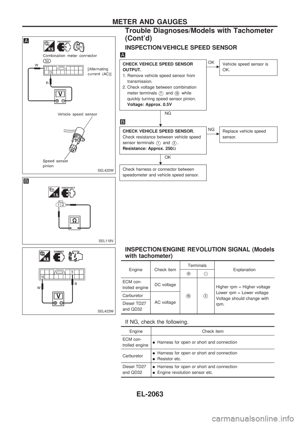
INSPECTION/VEHICLE SPEED SENSOR
CHECK VEHICLE SPEED SENSOR
OUTPUT.
1. Remove vehicle speed sensor from
transmission.
2. Check voltage between combination
meter terminals
V7andV15while
quickly turning speed sensor pinion.
Voltage: Approx. 0.5V
NG
cOK
Vehicle speed sensor is
OK.
CHECK VEHICLE SPEED SENSOR.
Check resistance between vehicle speed
sensor terminals
V1andV2.
Resistance: Approx. 250W
OK
cNG
Replace vehicle speed
sensor.
Check harness or connector between
speedometer and vehicle speed sensor.
INSPECTION/ENGINE REVOLUTION SIGNAL (Models
with tachometer)
Engine Check itemTerminals
ExplanationÅ@
ECM con-
trolled engineDC voltage
V16V3
Higher rpm = Higher voltage
Lower rpm = Lower voltage
Voltage should change with
rpm. Carburetor
AC voltage
Diesel TD27
and QD32
If NG, check the following.
Engine Check item
ECM con-
trolled engine
lHarness for open or short and connection
Carburetor
lHarness for open or short and connection
lResistor etc.
Diesel TD27
and QD32
lHarness for open or short and connection
lEngine revolution sensor etc.
SEL422W
SEL118V
SEL423W
.
.
METER AND GAUGES
Trouble Diagnoses/Models with Tachometer
(Cont'd)
EL-2063
Page 147 of 666
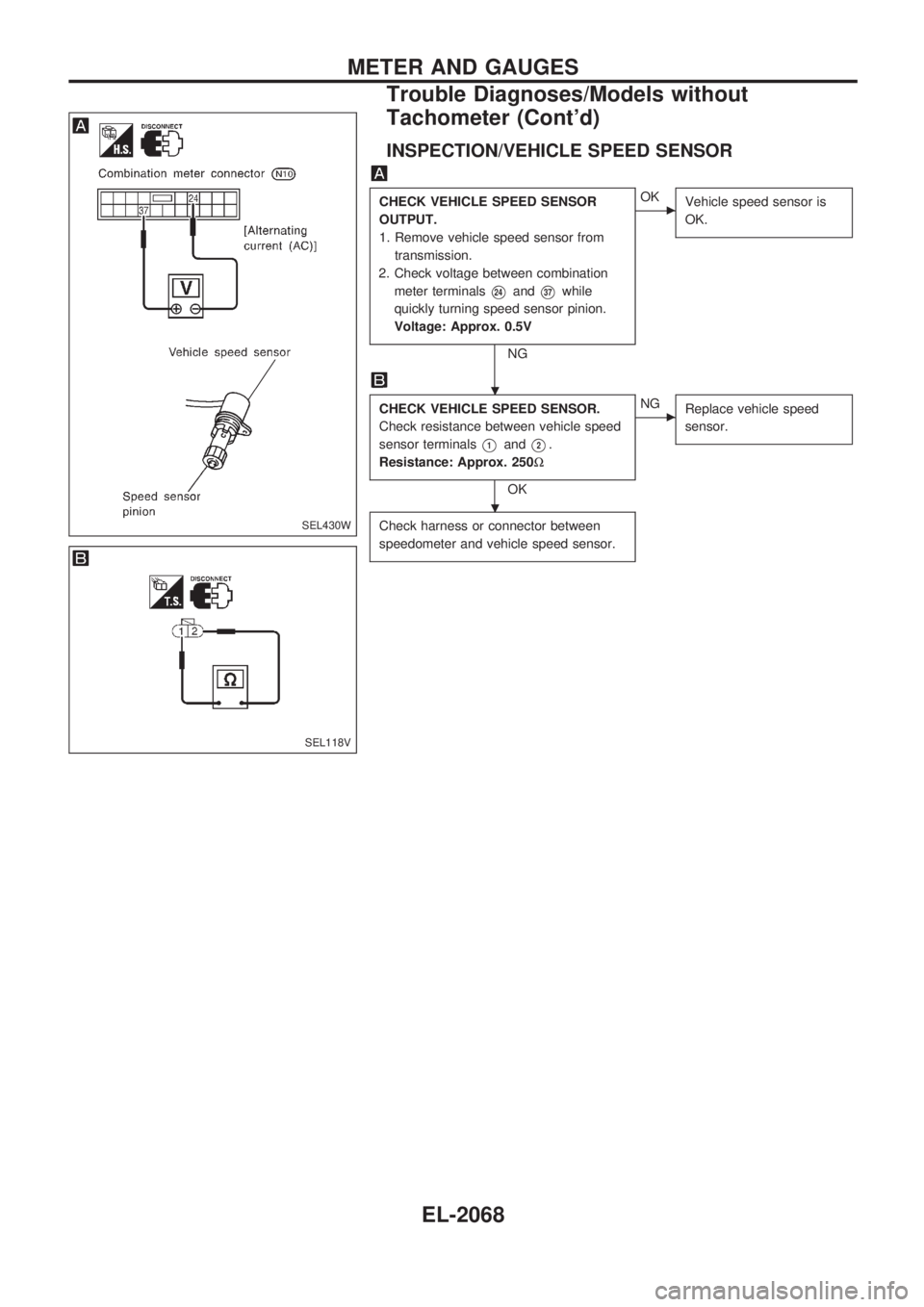
INSPECTION/VEHICLE SPEED SENSOR
CHECK VEHICLE SPEED SENSOR
OUTPUT.
1. Remove vehicle speed sensor from
transmission.
2. Check voltage between combination
meter terminals
V24andV37while
quickly turning speed sensor pinion.
Voltage: Approx. 0.5V
NG
cOK
Vehicle speed sensor is
OK.
CHECK VEHICLE SPEED SENSOR.
Check resistance between vehicle speed
sensor terminals
V1andV2.
Resistance: Approx. 250W
OK
cNG
Replace vehicle speed
sensor.
Check harness or connector between
speedometer and vehicle speed sensor.SEL430W
SEL118V
.
.
METER AND GAUGES
Trouble Diagnoses/Models without
Tachometer (Cont'd)
EL-2068
Page 150 of 666
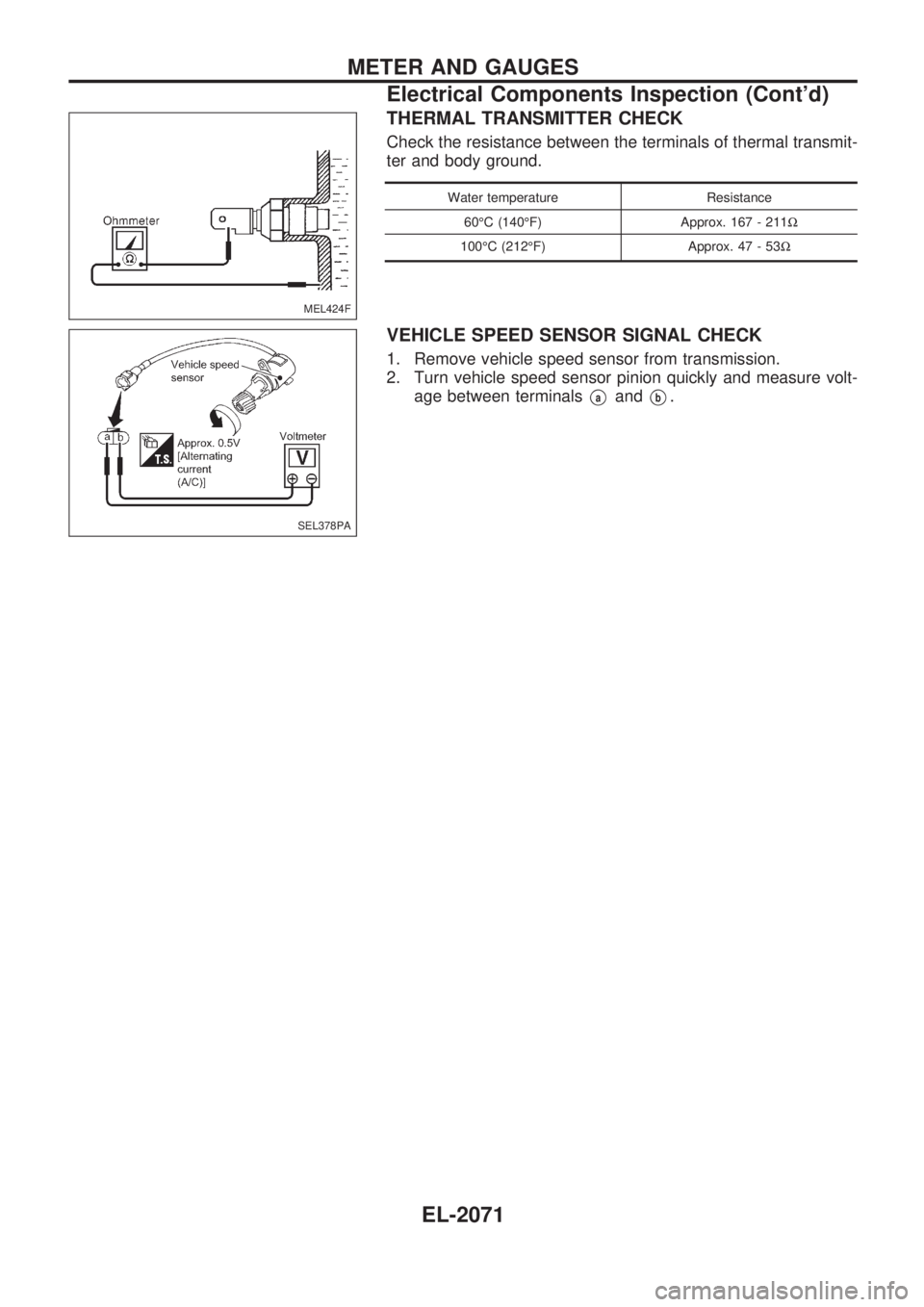
THERMAL TRANSMITTER CHECK
Check the resistance between the terminals of thermal transmit-
ter and body ground.
Water temperature Resistance
60ÉC (140ÉF) Approx. 167 - 211W
100ÉC (212ÉF) Approx. 47 - 53W
VEHICLE SPEED SENSOR SIGNAL CHECK
1. Remove vehicle speed sensor from transmission.
2. Turn vehicle speed sensor pinion quickly and measure volt-
age between terminals
VaandVb.
MEL424F
SEL378PA
METER AND GAUGES
Electrical Components Inspection (Cont'd)
EL-2071
Page 314 of 666
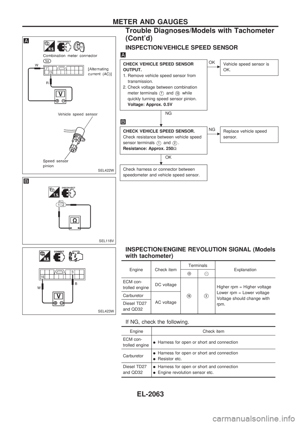
INSPECTION/VEHICLE SPEED SENSOR
CHECK VEHICLE SPEED SENSOR
OUTPUT.
1. Remove vehicle speed sensor from
transmission.
2. Check voltage between combination
meter terminals
V7andV15while
quickly turning speed sensor pinion.
Voltage: Approx. 0.5V
NG
cOK
Vehicle speed sensor is
OK.
CHECK VEHICLE SPEED SENSOR.
Check resistance between vehicle speed
sensor terminals
V1andV2.
Resistance: Approx. 250W
OK
cNG
Replace vehicle speed
sensor.
Check harness or connector between
speedometer and vehicle speed sensor.
INSPECTION/ENGINE REVOLUTION SIGNAL (Models
with tachometer)
Engine Check itemTerminals
ExplanationÅ@
ECM con-
trolled engineDC voltage
V16V3
Higher rpm = Higher voltage
Lower rpm = Lower voltage
Voltage should change with
rpm. Carburetor
AC voltage
Diesel TD27
and QD32
If NG, check the following.
Engine Check item
ECM con-
trolled engine
lHarness for open or short and connection
Carburetor
lHarness for open or short and connection
lResistor etc.
Diesel TD27
and QD32
lHarness for open or short and connection
lEngine revolution sensor etc.
SEL422W
SEL118V
SEL423W
.
.
METER AND GAUGES
Trouble Diagnoses/Models with Tachometer
(Cont'd)
EL-2063
Page 319 of 666
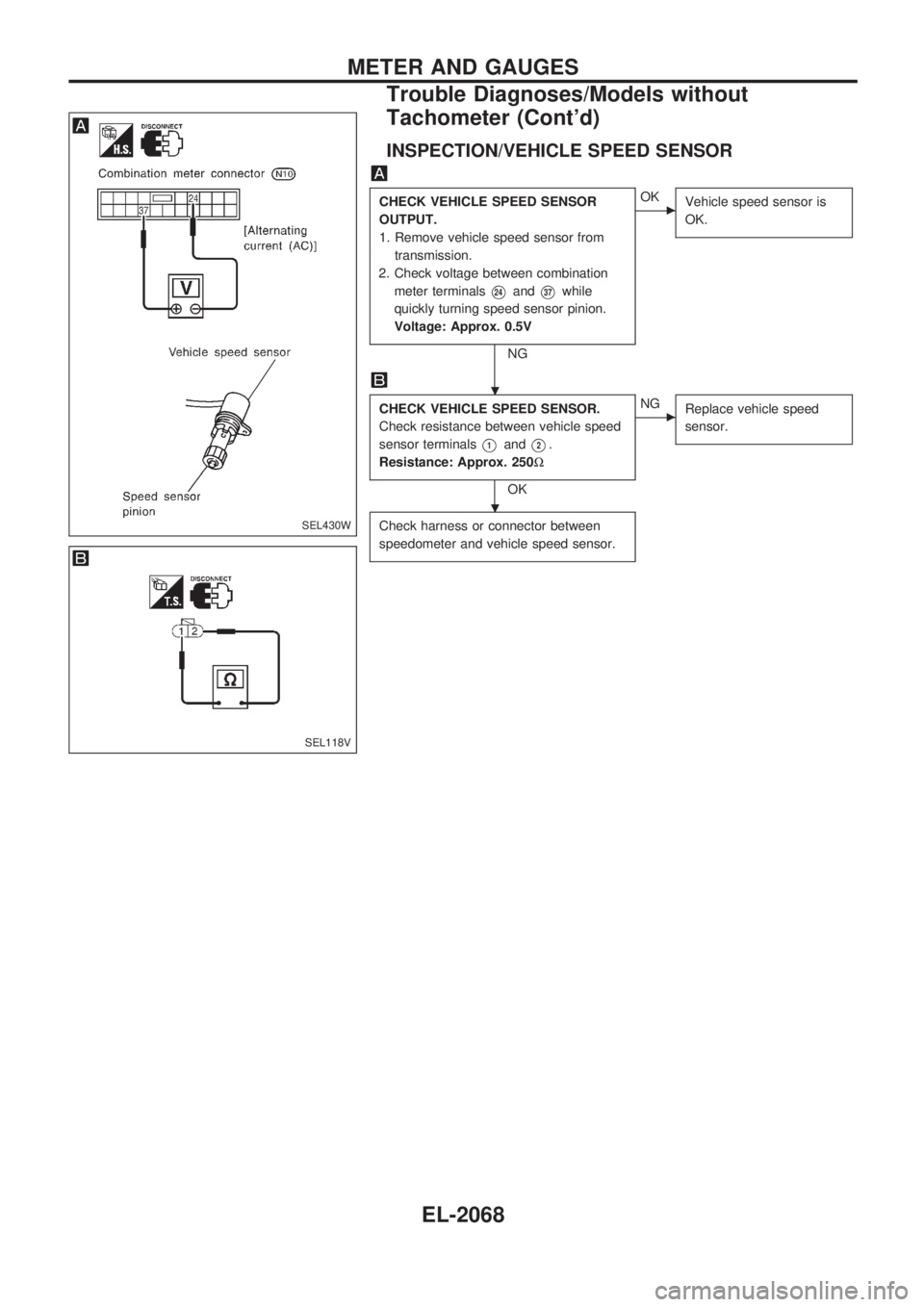
INSPECTION/VEHICLE SPEED SENSOR
CHECK VEHICLE SPEED SENSOR
OUTPUT.
1. Remove vehicle speed sensor from
transmission.
2. Check voltage between combination
meter terminals
V24andV37while
quickly turning speed sensor pinion.
Voltage: Approx. 0.5V
NG
cOK
Vehicle speed sensor is
OK.
CHECK VEHICLE SPEED SENSOR.
Check resistance between vehicle speed
sensor terminals
V1andV2.
Resistance: Approx. 250W
OK
cNG
Replace vehicle speed
sensor.
Check harness or connector between
speedometer and vehicle speed sensor.SEL430W
SEL118V
.
.
METER AND GAUGES
Trouble Diagnoses/Models without
Tachometer (Cont'd)
EL-2068
Page 322 of 666
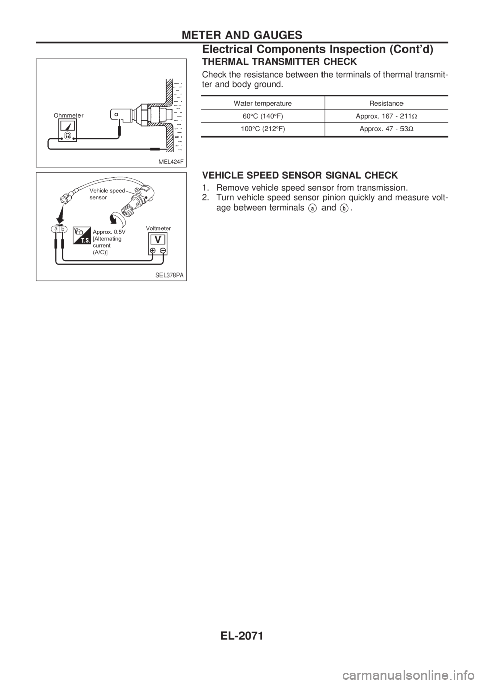
THERMAL TRANSMITTER CHECK
Check the resistance between the terminals of thermal transmit-
ter and body ground.
Water temperature Resistance
60ÉC (140ÉF) Approx. 167 - 211W
100ÉC (212ÉF) Approx. 47 - 53W
VEHICLE SPEED SENSOR SIGNAL CHECK
1. Remove vehicle speed sensor from transmission.
2. Turn vehicle speed sensor pinion quickly and measure volt-
age between terminals
VaandVb.
MEL424F
SEL378PA
METER AND GAUGES
Electrical Components Inspection (Cont'd)
EL-2071
Page 464 of 666

WARNING:
lPosition vehicle on a flat and solid surface.
lPlace chocks at front and back of rear wheels.
lDo not remove engine until exhaust system has com-
pletely cooled off.
Otherwise, you may burn yourself and/or fire may break
out in fuel line.
lBefore disconnecting fuel hose, release fuel pressure.
Refer to EC section (ªFuel Pressure Releaseº, ªBASIC
SERVICE PROCEDUREº).
lBe sure to hoist engine and transmission in a safe man-
ner.
lFor engines not equipped with engine slingers, attach
proper slingers and bolts described in PARTS CATA-
LOG.
CAUTION:
lWhen lifting engine, be sure to clear surrounding parts.
Take special care near accelerator wire casing, brake
lines and brake master cylinder.
lIn hoisting the engine, always use engine slingers in a
safe manner.
lFor 4WD models, apply sealant between engine and
transmission. Refer to MT section (ªRemoval and Instal-
lationº).
Removal
1. Drain coolant from engine block and radiator. Refer to MA
section (ªChanging Engine Coolantº, ªENGINE MAINTE-
NANCEº).
2. Release fuel pressure. Refer to EC section (ªFuel Pressure
Releaseº, ªBASIC SERVICE PROCEDUREº).
3. Remove negative battery cable.
4. Remove hood. Refer to BT section.
5. Remove air cleaner and air duct.
6. Remove power steering drive belt, alternator drive belt and
A/C compressor drive belt.
7. Remove radiator. Refer to LC section (ªRadiatorº, ªENGINE
COOLING SYSTEMº).
8. Remove exhaust manifold heat shield.
9. Disconnect exhaust system from exhaust manifold.
10. Remove A/C compressor from bracket. Refer to HA section
(ªCompressor Mountingº, ªSERVICE PROCEDURESº).
11. Disconnect accelerator wire, vacuum hoses, electrical
connectors, heater hoses and vacuum booster hose.
ENGINE REMOVALKA24DE
EM-2036
Page 465 of 666
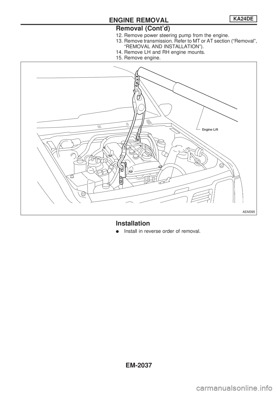
12. Remove power steering pump from the engine.
13. Remove transmission. Refer to MT or AT section (ªRemovalº,
ªREMOVAL AND INSTALLATIONº).
14. Remove LH and RH engine mounts.
15. Remove engine.
Installation
lInstall in reverse order of removal.
AEM395
ENGINE REMOVALKA24DE
Removal (Cont'd)
EM-2037
Page 497 of 666
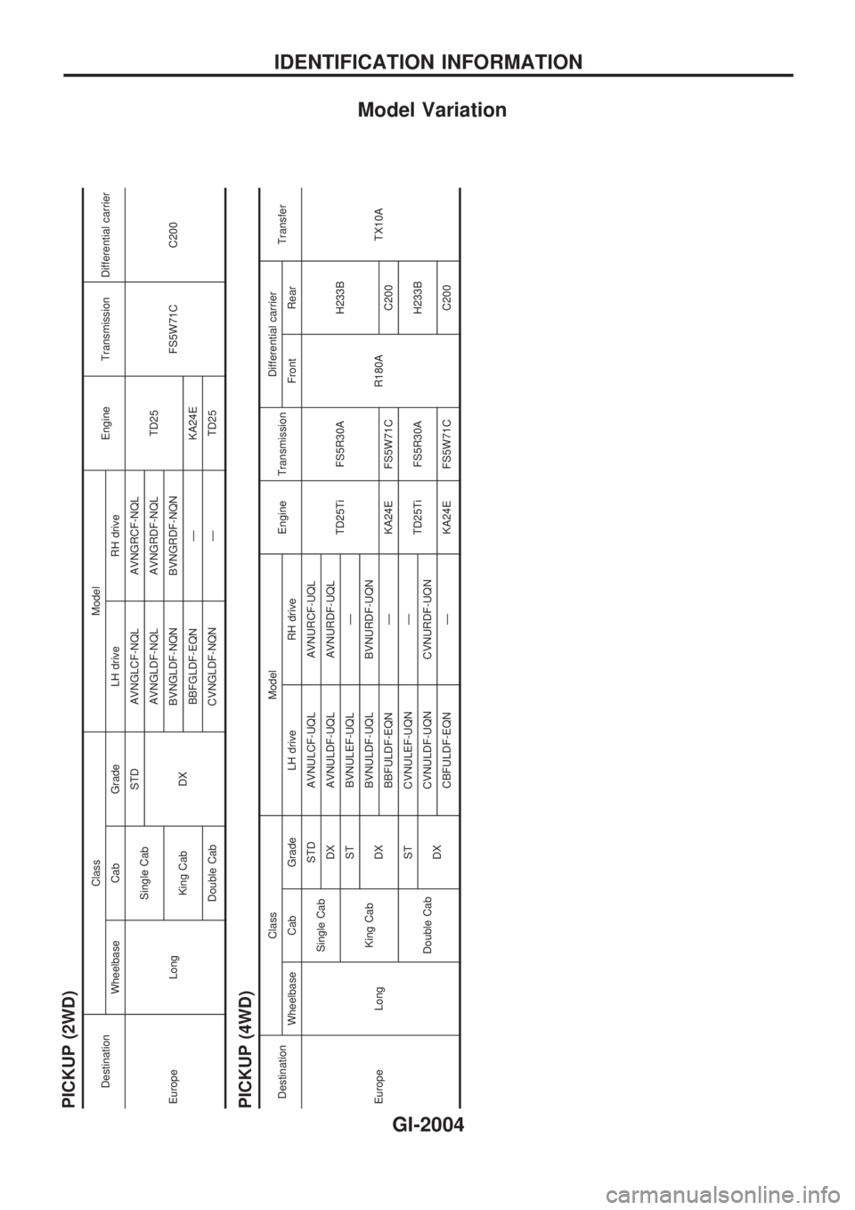
Model Variation
PICKUP (2WD)
DestinationClass Model
Engine Transmission Differential carrier
Wheelbase Cab Grade LH drive RH drive
Europe LongSingle CabSTD AVNGLCF-NQL AVNGRCF-NQL
TD25
FS5W71C C200
DXAVNGLDF-NQL AVNGRDF-NQL
King CabBVNGLDF-NQN BVNGRDF-NQN
BBFGLDF-EQN Ð KA24E
Double Cab CVNGLDF-NQN Ð TD25
PICKUP (4WD)DestinationClass Model
Engine TransmissionDifferential carrier
Transfer
Wheelbase Cab Grade LH drive RH drive Front Rear
Europe LongSingle CabSTD AVNULCF-UQL AVNURCF-UQL
TD25Ti FS5R30A
R180AH233B
TX10A DX AVNULDF-UQL AVNURDF-UQL
King CabST BVNULEF-UQL Ð
DXBVNULDF-UQL BVNURDF-UQN
BBFULDF-EQN Ð KA24E FS5W71C C200
Double CabST CVNULEF-UQN Ð
TD25Ti FS5R30A H233B
DXCVNULDF-UQN CVNURDF-UQN
CBFULDF-EQN Ð KA24E FS5W71C C200
IDENTIFICATION INFORMATION
GI-2004
Page 498 of 666
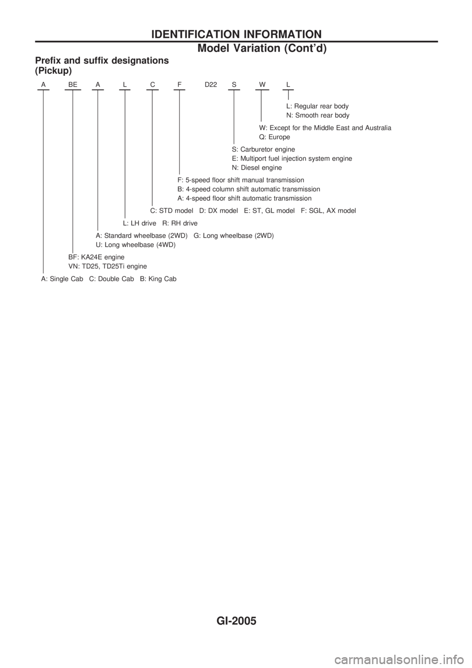
Prefix and suffix designations
(Pickup)
ABEALCFD22 SWL
L: Regular rear body
N: Smooth rear body
W: Except for the Middle East and Australia
Q: Europe
S: Carburetor engine
E: Multiport fuel injection system engine
N: Diesel engine
F: 5-speed floor shift manual transmission
B: 4-speed column shift automatic transmission
A: 4-speed floor shift automatic transmission
C: STD model D: DX model E: ST, GL model F: SGL, AX model
L: LH drive R: RH drive
A: Standard wheelbase (2WD) G: Long wheelbase (2WD)
U: Long wheelbase (4WD)
BF: KA24E engine
VN: TD25, TD25Ti engine
A: Single Cab C: Double Cab B: King Cab
IDENTIFICATION INFORMATION
Model Variation (Cont'd)
GI-2005