turn signal NISSAN PICK-UP 1999 Repair Manual
[x] Cancel search | Manufacturer: NISSAN, Model Year: 1999, Model line: PICK-UP, Model: NISSAN PICK-UP 1999Pages: 666, PDF Size: 16.21 MB
Page 80 of 666
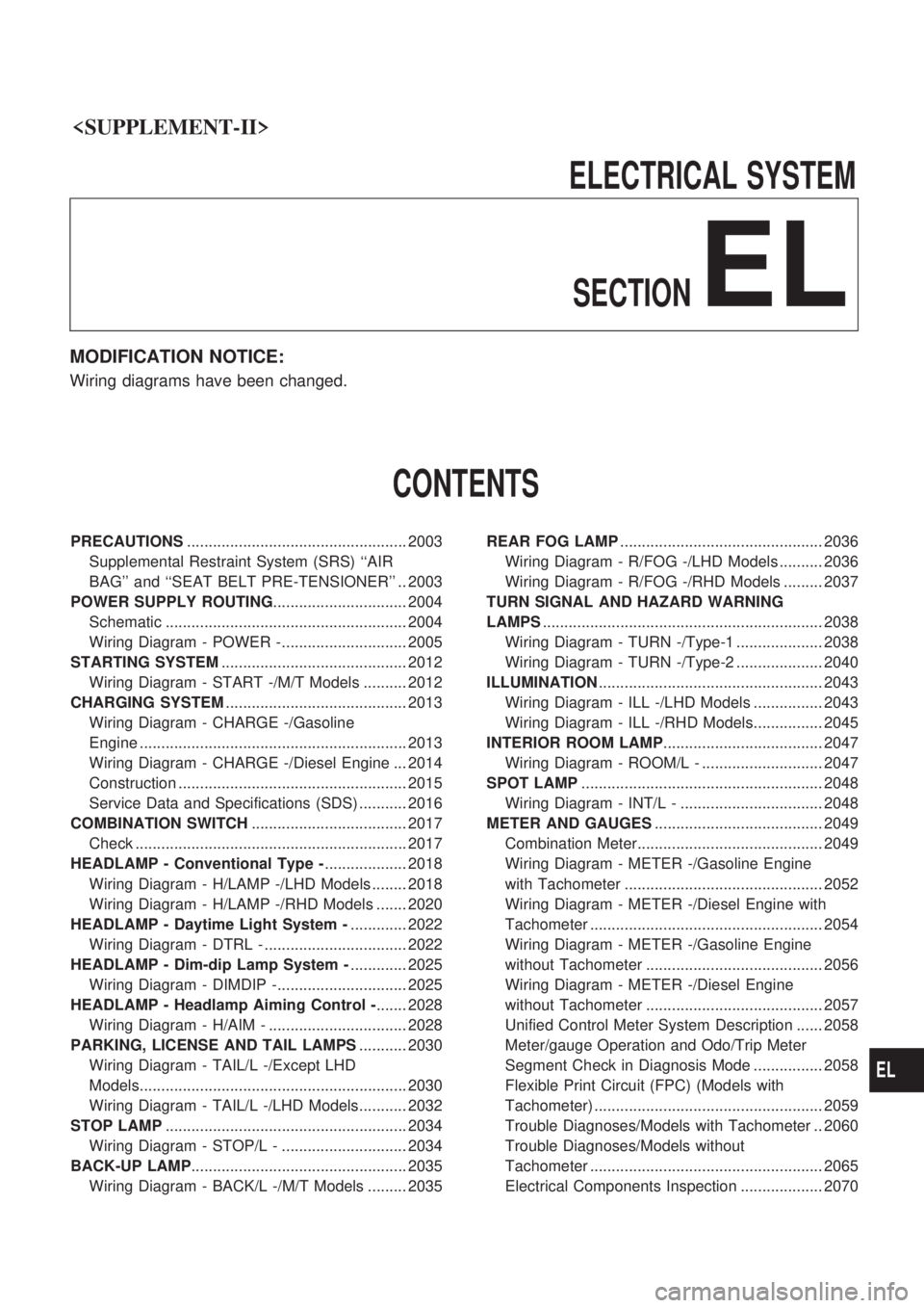
ELECTRICALSYSTEM
SECTION
EL
MODIFICATION NOTICE:
Wiring diagrams have been changed.
CONTENTS
PRECAUTIONS ................................................... 2003
Supplemental Restraint System (SRS) ``AIR
BAG'' and ``SEAT BELT PRE-TENSIONER'' .. 2003
POWER SUPPLY ROUTING ............................... 2004
Schematic ........................................................ 2004
Wiring Diagram - POWER -............................. 2005
STARTING SYSTEM ........................................... 2012
Wiring Diagram - START -/M/T Models .......... 2012
CHARGING SYSTEM .......................................... 2013
Wiring Diagram - CHARGE -/Gasoline
Engine .............................................................. 2013
Wiring Diagram - CHARGE -/Diesel Engine ... 2014
Construction ..................................................... 2015
Service Data and Specifications (SDS) ........... 2016
COMBINATION SWITCH .................................... 2017
Check ............................................................... 2017
HEADLAMP - Conventional Type - ................... 2018
Wiring Diagram - H/LAMP -/LHD Models ........ 2018
Wiring Diagram - H/LAMP -/RHD Models ....... 2020
HEADLAMP - Daytime Light System - ............. 2022
Wiring Diagram - DTRL - ................................. 2022
HEADLAMP - Dim-dip Lamp System - ............. 2025
Wiring Diagram - DIMDIP -.............................. 2025
HEADLAMP - Headlamp Aiming Control - ....... 2028
Wiring Diagram - H/AIM - ................................ 2028
PARKING, LICENSE AND TAIL LAMPS ........... 2030
Wiring Diagram - TAIL/L -/Except LHD
Models.............................................................. 2030
Wiring Diagram - TAIL/L -/LHD Models........... 2032
STOP LAMP ........................................................ 2034
Wiring Diagram - STOP/L - ............................. 2034
BACK-UP LAMP .................................................. 2035
Wiring Diagram - BACK/L -/M/T Models ......... 2035 REAR FOG LAMP
............................................... 2036
Wiring Diagram - R/FOG -/LHD Models .......... 2036
Wiring Diagram - R/FOG -/RHD Models ......... 2037
TURN SIGNAL AND HAZARD WARNING
LAMPS ................................................................. 2038
Wiring Diagram - TURN -/Type-1 .................... 2038
Wiring Diagram - TURN -/Type-2 .................... 2040
ILLUMINATION .................................................... 2043
Wiring Diagram - ILL -/LHD Models ................ 2043
Wiring Diagram - ILL -/RHD Models................ 2045
INTERIOR ROOM LAMP ..................................... 2047
Wiring Diagram - ROOM/L - ............................ 2047
SPOT LAMP ........................................................ 2048
Wiring Diagram - INT/L - ................................. 2048
METER AND GAUGES ....................................... 2049
Combination Meter........................................... 2049
Wiring Diagram - METER -/Gasoline Engine
with Tachometer .............................................. 2052
Wiring Diagram - METER -/Diesel Engine with
Tachometer ...................................................... 2054
Wiring Diagram - METER -/Gasoline Engine
without Tachometer ......................................... 2056
Wiring Diagram - METER -/Diesel Engine
without Tachometer ......................................... 2057
Unified Control Meter System Description ...... 2058
Meter/gauge Operation and Odo/Trip Meter
Segment Check in Diagnosis Mode ................ 2058
Flexible Print Circuit (FPC) (Models with
Tachometer) ..................................................... 2059
Trouble Diagnoses/Models with Tachometer .. 2060
Trouble Diagnoses/Models without
Tachometer ...................................................... 2065
Electrical Components Inspection ................... 2070
EL
Page 117 of 666
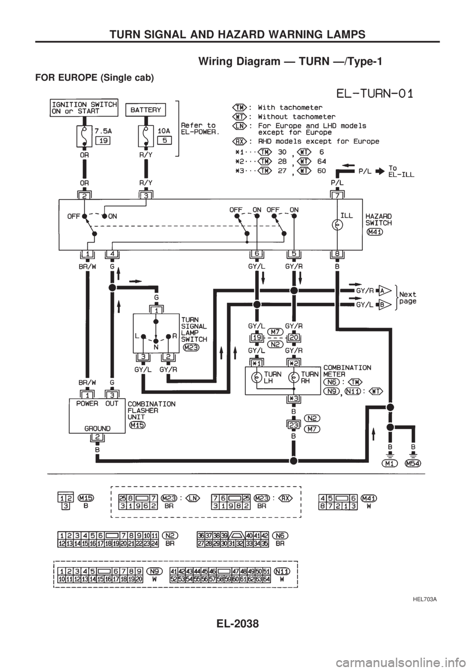
Wiring Diagram Ð TURN Ð/Type-1
FOR EUROPE (Single cab)
HEL703A
TURN SIGNAL AND HAZARD WARNING LAMPS
EL-2038
Page 118 of 666
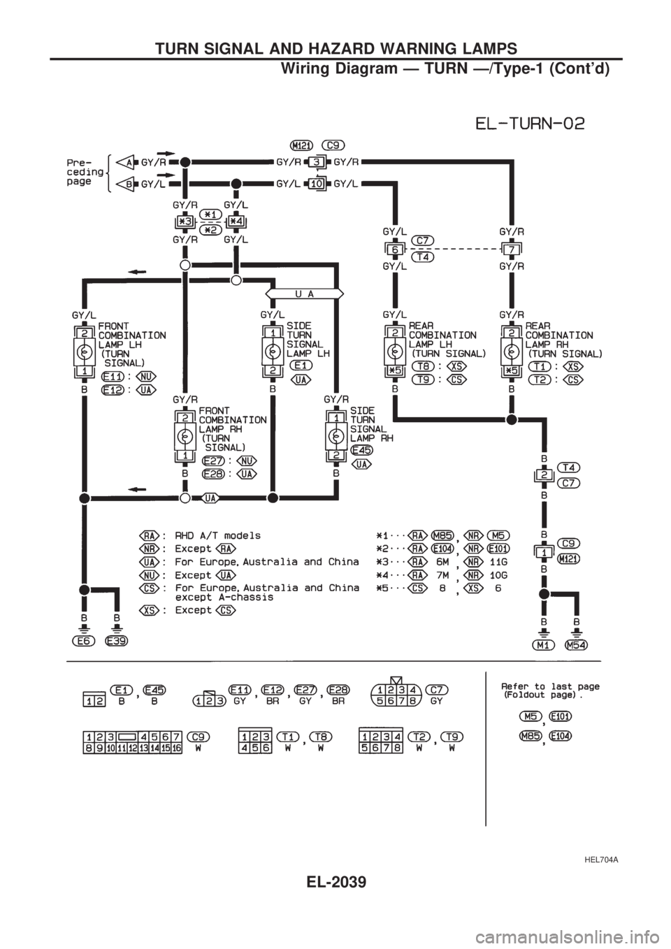
HEL704A
TURN SIGNAL AND HAZARD WARNING LAMPS
Wiring Diagram Ð TURN Ð/Type-1 (Cont'd)
EL-2039
Page 119 of 666
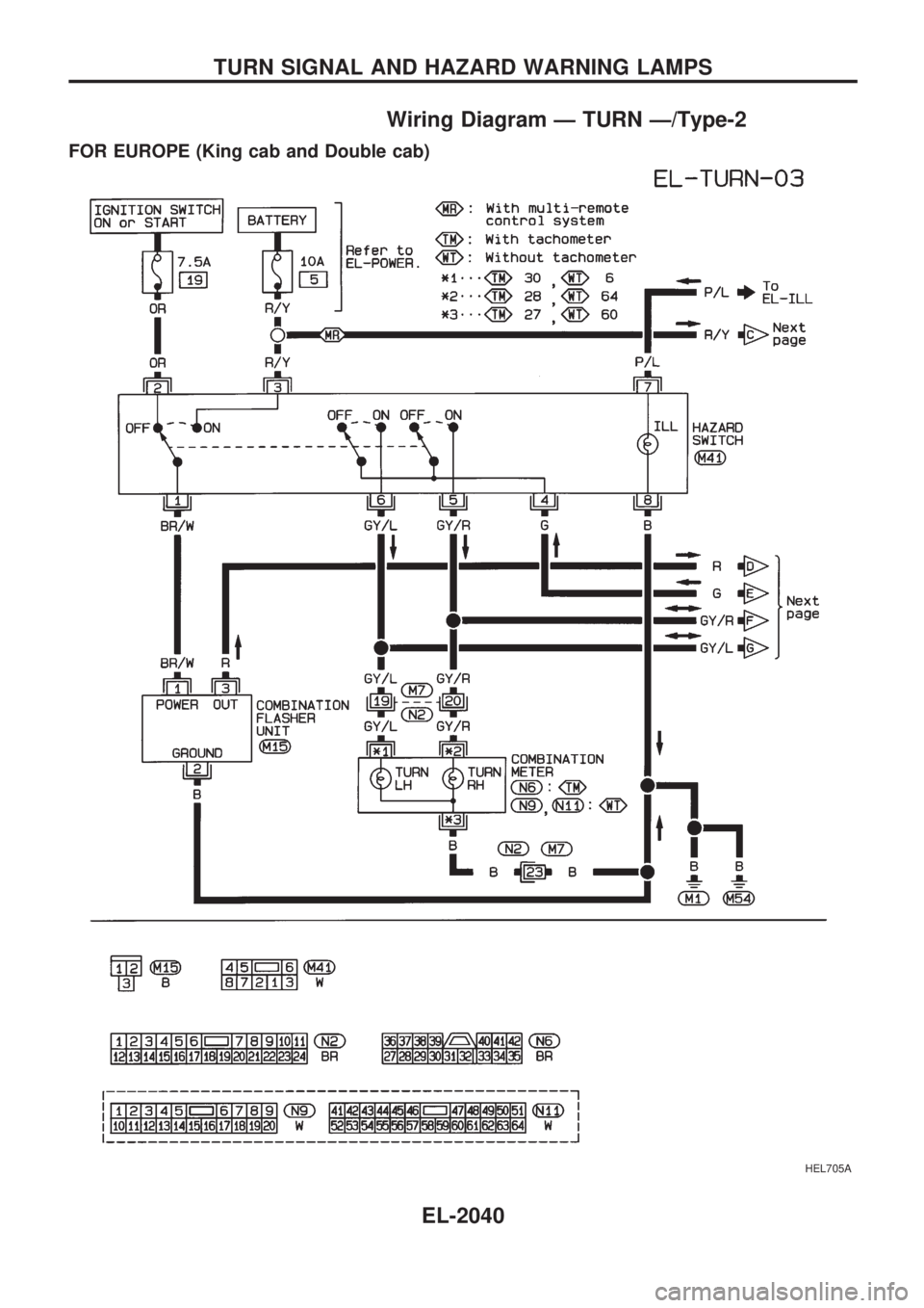
Wiring Diagram Ð TURN Ð/Type-2
FOR EUROPE (King cab and Double cab)
HEL705A
TURN SIGNAL AND HAZARD WARNING LAMPS
EL-2040
Page 120 of 666
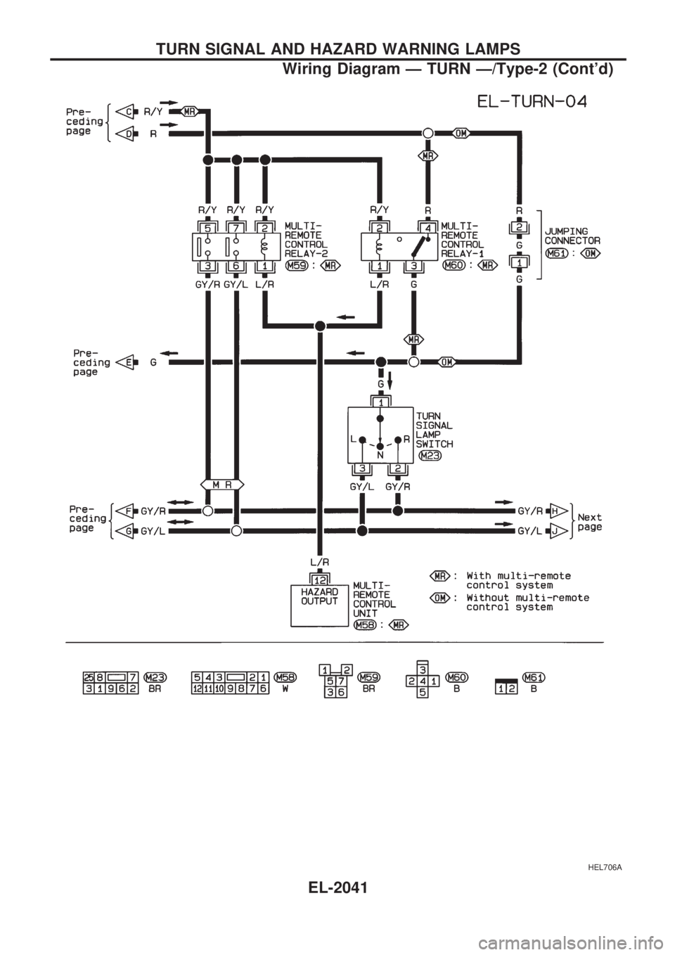
HEL706A
TURN SIGNAL AND HAZARD WARNING LAMPS
Wiring Diagram Ð TURN Ð/Type-2 (Cont'd)
EL-2041
Page 121 of 666
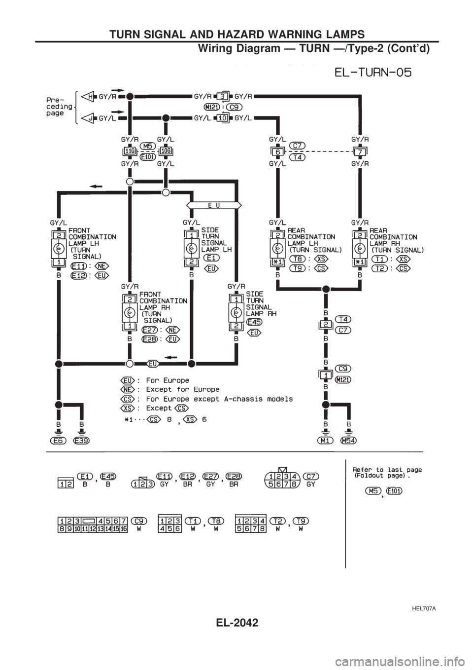
HEL707A
TURN SIGNAL AND HAZARD WARNING LAMPS
Wiring Diagram Ð TURN Ð/Type-2 (Cont'd)
EL-2042
Page 142 of 666
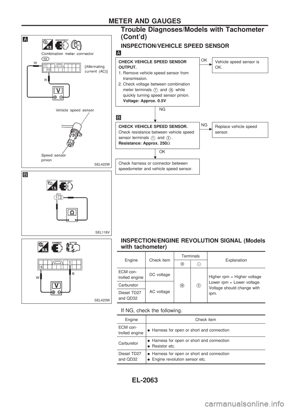
INSPECTION/VEHICLE SPEED SENSOR
CHECK VEHICLE SPEED SENSOR
OUTPUT.
1. Remove vehicle speed sensor from
transmission.
2. Check voltage between combination
meter terminals
V7andV15while
quickly turning speed sensor pinion.
Voltage: Approx. 0.5V
NG
cOK
Vehicle speed sensor is
OK.
CHECK VEHICLE SPEED SENSOR.
Check resistance between vehicle speed
sensor terminals
V1andV2.
Resistance: Approx. 250W
OK
cNG
Replace vehicle speed
sensor.
Check harness or connector between
speedometer and vehicle speed sensor.
INSPECTION/ENGINE REVOLUTION SIGNAL (Models
with tachometer)
Engine Check itemTerminals
ExplanationÅ@
ECM con-
trolled engineDC voltage
V16V3
Higher rpm = Higher voltage
Lower rpm = Lower voltage
Voltage should change with
rpm. Carburetor
AC voltage
Diesel TD27
and QD32
If NG, check the following.
Engine Check item
ECM con-
trolled engine
lHarness for open or short and connection
Carburetor
lHarness for open or short and connection
lResistor etc.
Diesel TD27
and QD32
lHarness for open or short and connection
lEngine revolution sensor etc.
SEL422W
SEL118V
SEL423W
.
.
METER AND GAUGES
Trouble Diagnoses/Models with Tachometer
(Cont'd)
EL-2063
Page 150 of 666
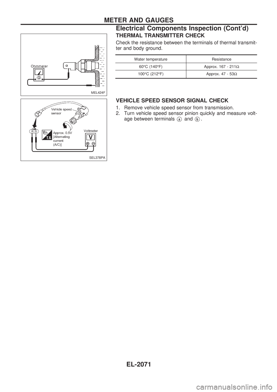
THERMAL TRANSMITTER CHECK
Check the resistance between the terminals of thermal transmit-
ter and body ground.
Water temperature Resistance
60ÉC (140ÉF) Approx. 167 - 211W
100ÉC (212ÉF) Approx. 47 - 53W
VEHICLE SPEED SENSOR SIGNAL CHECK
1. Remove vehicle speed sensor from transmission.
2. Turn vehicle speed sensor pinion quickly and measure volt-
age between terminals
VaandVb.
MEL424F
SEL378PA
METER AND GAUGES
Electrical Components Inspection (Cont'd)
EL-2071
Page 193 of 666
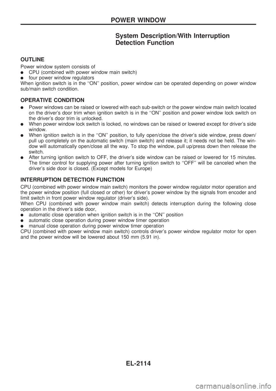
System Description/With Interruption
Detection Function
OUTLINE
Power window system consists of
lCPU (combined with power window main switch)
lfour power window regulators
When ignition switch is in the ``ON'' position, power window can be operated depending on power window
sub/main switch condition.
OPERATIVE CONDITION
lPower windows can be raised or lowered with each sub-switch or the power window main switch located
on the driver's door trim when ignition switch is in the ``ON'' position and power window lock switch on
the driver's door trim is unlocked.
lWhen power window lock switch is locked, no windows can be raised or lowered except for driver's side
window.
lWhen ignition switch is in the ``ON'' position, to fully open/close the driver's side window, press down/
pull up completely on the automatic switch (main switch) and release it; it needs not be held. The win-
dow will automatically open/close all the way. To stop the window, pull up/press down then release the
switch.
lAfter turning ignition switch to OFF, the driver's side window can be raised or lowered for 15 minutes.
The timer control for supplying power after turning ignition switch to ``OFF'' will be canceled when the
driver's side door is closed. (Except models for Europe)
INTERRUPTION DETECTION FUNCTION
CPU (combined with power window main switch) monitors the power window regulator motor operation and
the power window position (full closed or other) for driver's power window by the signals from encoder and
limit switch in front power window regulator (driver's side).
When CPU (combined with power window main switch) detects interruption during the following close
operation in the driver's side door,
lautomatic close operation when ignition switch is in the ``ON'' position
lautomatic close operation during power window timer operation
lmanual close operation during power window timer operation
CPU (combined with power window main switch) controls driver's power window regulator motor for open
and the power window will be lowered about 150 mm (5.91 in).
POWER WINDOW
EL-2114
Page 199 of 666
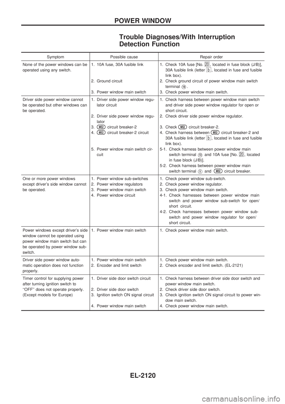
Trouble Diagnoses/With Interruption
Detection Function
Symptom Possible cause Repair order
None of the power windows can be
operated using any switch.1. 10A fuse, 30A fusible link
2. Ground circuit
3. Power window main switch1. Check 10A fuse [No.
20, located in fuse block (J/B)],
30A fusible link (letter
b, located in fuse and fusible
link box).
2. Check ground circuit of power window main switch
terminal
V19.
3. Check power window main switch.
Driver side power window cannot
be operated but other windows can
be operated.1. Driver side power window regu-
lator circuit
2. Driver side power window regu-
lator
3.
M52circuit breaker-2
4.
M52circuit breaker-2 circuit
5. Power window main switch cir-
cuit1. Check harness between power window main switch
and driver side power window regulator for open or
short circuit.
2. Check driver side power window regulator.
3. Check
M52circuit breaker-2.
4. Check harness between
M52circuit breaker-2 and
30A fusible link (letter
b, located in fuse and fusible
link box).
5-1. Check harness between power window main
switch terminal
V13and 10A fuse [No.20, located
in fuse block (J/B)].
5-2. Check harness between power window main
switch terminal
V5andM52circuit breaker.
One or more power windows
except driver's side window cannot
be operated.1. Power window sub-switches
2. Power window regulators
3. Power window main switch
4. Power window circuit1. Check power window sub-switch.
2. Check power window regulator.
3. Check power window main switch.
4-1. Check harnesses between power window main
switch and power window sub-switch for open/
short circuit.
4-2. Check harnesses between power window sub-
switch and power window regulator for open/
short circuit.
Power windows except driver's side
window cannot be operated using
power window main switch but can
be operated by power window sub-
switch.1. Power window main switch 1. Check power window main switch.
Driver side power window auto-
matic operation does not function
properly.1. Power window main switch
2. Encoder and limit switch1. Check power window main switch.
2. Check encoder and limit switch. (EL-2121)
Timer control for supplying power
after turning ignition switch to
``OFF'' does not operate properly.
(Except models for Europe)1. Driver side door switch circuit
2. Driver side door switch
3. Ignition switch ON signal circuit
4. Power window main switch1. Check harness between driver side door switch and
power window main switch.
2. Check driver side door switch.
3. Check ignition switch ON signal circuit to power win-
dow main switch.
4. Check power window main switch.
POWER WINDOW
EL-2120