belt NISSAN PICK-UP 2003 Repair Manual
[x] Cancel search | Manufacturer: NISSAN, Model Year: 2003, Model line: PICK-UP, Model: NISSAN PICK-UP 2003Pages: 229, PDF Size: 8.89 MB
Page 5 of 229
ENGINE CONTROL SYSTEM
SECTION
EC
CONTENTS
PRECAUTIONS AND PREPARATION............... 4002
Supplemental Restraint System (SRS) ``AIR
BAG'' and ``SEAT BELT PRE-TENSIONER'' .. 4002
KA24DE
TROUBLE DIAGNOSIS FOR
NON-DETECTABLE ITEMS................................ 4003
Electrical Load Signal ...................................... 4003
IACV-FICD Solenoid Valve .............................. 4005
KA24DE (EURO OBD)
ENGINE AND EMISSION CONTROL OVERALL
SYSTEM...............................................................4006
Circuit Diagram ................................................ 4006IACV-FICD SOLENOID VALVE.......................... 4007
Wiring Diagram ................................................ 4007
Diagnostic Procedure....................................... 4009
YD25DDTi
ENGINE AND EMISSION CONTROL OVERALL
SYSTEM...............................................................4013
Circuit Diagram ................................................ 4013
DTC 0208 OVER HEAT....................................... 4014
Wiring Diagram ................................................ 4014
GLOW CONTROL SYSTEM............................... 4015
Wiring Diagram ................................................ 4015
AIR CONDITIONER CONTROL.......................... 4016
Wiring Diagram ................................................ 4016
When you read wiring diagrams:
lRead GI section, ªHOW TO READ WIRING DIAGRAMSº.
lSee EL section, ªPOWER SUPPLY ROUTINGº for power distribution circuit.
When you perform trouble diagnoses, read GI section, ªHOW TO FOLLOW FLOW CHART IN
TROUBLE DIAGNOSESº and ªHOW TO PERFORM EFFICIENT DIAGNOSIS FOR AN ELECTRICAL
INCIDENTº.
EC
Page 6 of 229
Supplemental Restraint System (SRS) ªAIR
BAGº and ªSEAT BELT PRE-TENSIONERº
The Supplemental Restraint System such as ªAIR BAGº and ªSEAT BELT PRE-TENSIONERº used along
with a seat belt, helps to reduce the risk or severity of injury to the driver and front passenger in a frontal
collision. The SRS system composition which is available to NISSAN MODEL D22 is as follows (The com-
position varies according to the destination and optional equipment.):
Driver air bag module (located in the center of the steering wheel), front passenger air bag module (located
on the instrument panel on passenger side), seat belt pre-tensioner, a diagnosis sensor unit, warning lamp,
wiring harness and spiral cable.
Information necessary to service the system safely is included in theRS sectionof this Service Manual.
WARNING:
lTo avoid rendering the SRS inoperative, which could increase the risk of personal injury or death
in the event of a collision which would result in air bag inflation, all maintenance must be per-
formed by an authorized NISSAN dealer.
lImproper maintenance, including incorrect removal and installation of the SRS, can lead to per-
sonal injury caused by unintentional activation of the system. For removal of Spiral Cable and
Air Bag Module, see the RS section.
lDo not use electrical test equipment on any circuit related to the SRS unless instructed to in this
Service Manual. Spiral Cable and wiring harnesses (except ªSEAT BELT PRE-TENSIONERº) cov-
ered with yellow insulation either just before the harness connectors or for the complete harness
are related to the SRS.
PRECAUTIONS AND PREPARATION
EC-4002
Page 26 of 229

Side Step
REMOVAL Ð Side step assembly
V1Remove front kicking plate (left/right).
V2Remove rear kicking plate (left/right).
V3Remove dash side finisher (left/right).
V4Remove front seat (left/right).
V5Disconnect front seat belt harness connector (right).
V6Remove bolts of side step (front).
V7Remove bolts of side step (rear).
V8Remove bolts of side step (center).
V9Remove side step assembly.
PIIA6339E
EXTERIOR
BT-4005
Page 30 of 229
ELECTRICAL SYSTEM
SECTION
EL
MODIFICATION NOTICE:
lWiring diagrams have been changed.
lHarness layouts have been changed.
lFog lamp system has been changed.
lCD auto-changer has been added.
CONTENTS
PRECAUTIONS................................................... 4002
Supplemental Restraint System (SRS)²AIR
BAG²and²SEAT BELT PRE-TENSIONER².. 4002
POWER SUPPLY ROUTING............................... 4003
Schematic ........................................................ 4003
Wiring Diagram - POWER -............................. 4004
COMBINATION SWITCH.................................... 4011
HEADLAMP - Headlamp Aiming Control -....... 4012
Wiring Diagram - H/AIM - ................................ 4012
PARKING, LICENSE AND TAIL LAMPS........... 4014
Wiring Diagram - TAIL/L -/LHD Models........... 4014
FRONT FOG LAMP............................................. 4016
Wiring Diagram - F/FOG -/LHD Models .......... 4016
Wiring Diagram - F/FOG -/RHD Models.......... 4017
REAR FOG LAMP............................................... 4018
Wiring Diagram - R/FOG -/LHD Models
without Front Fog Lamp................................... 4018
Wiring Diagram - R/FOG -/RHD Models
without Front Fog Lamp................................... 4019
Wiring Diagram - R/FOG -/LHD Models with
Front Fog Lamp ............................................... 4020
Wiring Diagram - R/FOG -/RHD Models with
Front Fog Lamp ............................................... 4022
INTERIOR ROOM LAMP..................................... 4023
Wiring Diagram - ROOM/L - ............................ 4023
ILLUMINATION.................................................... 4024
Wiring Diagram - ILL -/LHD Models ................ 4024
Wiring Diagram - ILL -/RHD Models................ 4026
METER AND GAUGES....................................... 4028
Wiring Diagram - METER -/Gasoline Engine
with Tachometer .............................................. 4028WARNING LAMPS.............................................. 4030
Schematic/With Tachometer ............................ 4030
Schematic/Without Tachometer ....................... 4031
Wiring Diagram - WARN -/Gasoline Engine
with Tachometer .............................................. 4032
Wiring Diagram - WARN -/Gasoline Engine
without Tachometer ......................................... 4036
Wiring Diagram - WARN -/Diesel Engine with
Tachometer ...................................................... 4040
Wiring Diagram - WARN -/Diesel Engine
without Tachometer ......................................... 4044
WARNING CHIME............................................... 4049
Wiring Diagram - CHIME -/LHD Models.......... 4049
AUDIO.................................................................. 4050
Wiring Diagram - AUDIO -/LHD Models .......... 4050
Wiring Diagram - AUDIO -/RHD Models ......... 4052
NATS (Nissan Anti-Theft System).................... 4054
Wiring Diagram - NATS -/LHD Models............ 4054
Wiring Diagram - NATS -/RHD Models ........... 4055
HARNESS LAYOUT............................................ 4056
Main Harness ................................................... 4056
Engine Room Harness..................................... 4062
Engine Control Harness................................... 4068
Chassis Harness and Tail Harness ................. 4071
Room Lamp Harness/LHD Models .................. 4072
Room Lamp Harness/RHD Models ................. 4073
WIRING DIAGRAM CODES (CELL CODES)..... 4074
SUPER MULTIPLE JUNCTION (SMJ)............... 4075
Terminal Arrangement ..................................... 4075
EL
Page 31 of 229
Supplemental Restraint System (SRS) ªAIR
BAGº and ªSEAT BELT PRE-TENSIONERº
The Supplemental Restraint System such as ªAIR BAGº and ªSEAT BELT PRE-TENSIONERº used along
with a seat belt, helps to reduce the risk or severity of injury to the driver and front passenger in a frontal
collision. The SRS composition which is available to NISSAN MODEL D22 is as follows (The composition
varies according to the destination and optional equipment.):
Driver air bag module (located in the center of the steering wheel), front passenger air bag module (located
on the instrument panel on passenger side), seat belt pre-tensioner, a diagnosis sensor unit, warning lamp,
wiring harness and spiral cable.
WARNING:
lTo avoid rendering the SRS inoperative, which could increase the risk of personal injury or death
in the event of a collision which would result in air bag inflation, all maintenance must be per-
formed by an authorized NISSAN dealer.
lImproper maintenance, including incorrect removal and installation of the SRS, can lead to per-
sonal injury caused by unintentional activation of the system.
lDo not use electrical test equipment on any circuit related to the SRS unless instructed to in this
Service Manual. SRS wiring harnesses can be identified by yellow harness connector.
PRECAUTIONS
EL-4002
Page 106 of 229
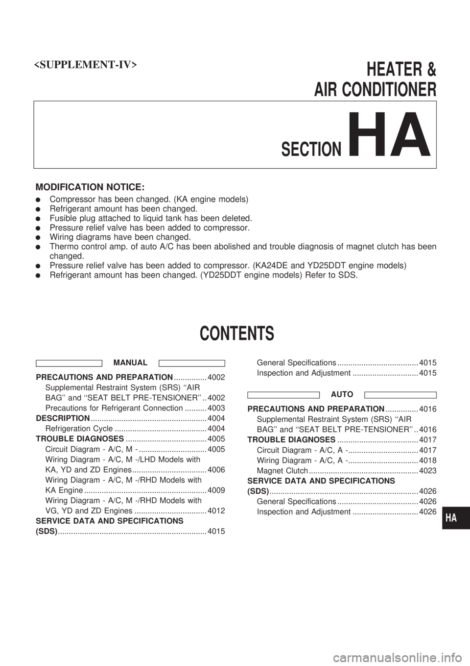
HEATER &
AIR CONDITIONER
SECTION
HA
MODIFICATION NOTICE:
lCompressor has been changed. (KA engine models)
lRefrigerant amount has been changed.
lFusible plug attached to liquid tank has been deleted.
lPressure relief valve has been added to compressor.
lWiring diagrams have been changed.
lThermo control amp. of auto A/C has been abolished and trouble diagnosis of magnet clutch has been
changed.
lPressure relief valve has been added to compressor. (KA24DE and YD25DDT engine models)
lRefrigerant amount has been changed. (YD25DDT engine models) Refer to SDS.
CONTENTS
MANUAL
PRECAUTIONS AND PREPARATION............... 4002
Supplemental Restraint System (SRS) ``AIR
BAG'' and ``SEAT BELT PRE-TENSIONER'' .. 4002
Precautions for Refrigerant Connection .......... 4003
DESCRIPTION..................................................... 4004
Refrigeration Cycle .......................................... 4004
TROUBLE DIAGNOSES..................................... 4005
Circuit Diagram - A/C, M - ............................... 4005
Wiring Diagram - A/C, M -/LHD Models with
KA, YD and ZD Engines .................................. 4006
Wiring Diagram - A/C, M -/RHD Models with
KA Engine ........................................................ 4009
Wiring Diagram - A/C, M -/RHD Models with
VG, YD and ZD Engines ................................. 4012
SERVICE DATA AND SPECIFICATIONS
(SDS).................................................................... 4015General Specifications ..................................... 4015
Inspection and Adjustment .............................. 4015
AUTO
PRECAUTIONS AND PREPARATION............... 4016
Supplemental Restraint System (SRS) ``AIR
BAG'' and ``SEAT BELT PRE-TENSIONER'' .. 4016
TROUBLE DIAGNOSES..................................... 4017
Circuit Diagram - A/C, A -................................ 4017
Wiring Diagram - A/C, A -................................ 4018
Magnet Clutch .................................................. 4023
SERVICE DATA AND SPECIFICATIONS
(SDS).................................................................... 4026
General Specifications ..................................... 4026
Inspection and Adjustment .............................. 4026
HA
Page 107 of 229
Supplemental Restraint System (SRS) ªAIR
BAGº and ªSEAT BELT PRE-TENSIONERº
The Supplemental Restraint System such as ªAIR BAGº and ªSEAT BELT PRE-TENSIONERº used along
with a seat belt, helps to reduce the risk or severity of injury to the driver and front passenger in a frontal
collision. The SRS composition which is available to NISSAN MODEL D22 is as follows (The composition
varies according to the destination and optional equipment.):
Driver air bag module (located in the center of the steering wheel), front passenger air bag module (located
on the instrument panel on passenger side), seat belt pre-tensioner, a diagnosis sensor unit, warning lamp,
wiring harness and spiral cable.
WARNING:
lTo avoid rendering the SRS inoperative, which could increase the risk of personal injury or death
in the event of a collision which would result in air bag inflation, all maintenance must be per-
formed by an authorized NISSAN dealer.
lImproper maintenance, including incorrect removal and installation of the SRS, can lead to per-
sonal injury caused by unintentional activation of the system.
lDo not use electrical test equipment on any circuit related to the SRS unless instructed to in this
Service Manual. SRS wiring harnesses can be identified by yellow harness connector.
PRECAUTIONS AND PREPARATIONMANUAL
HA-4002
Page 120 of 229
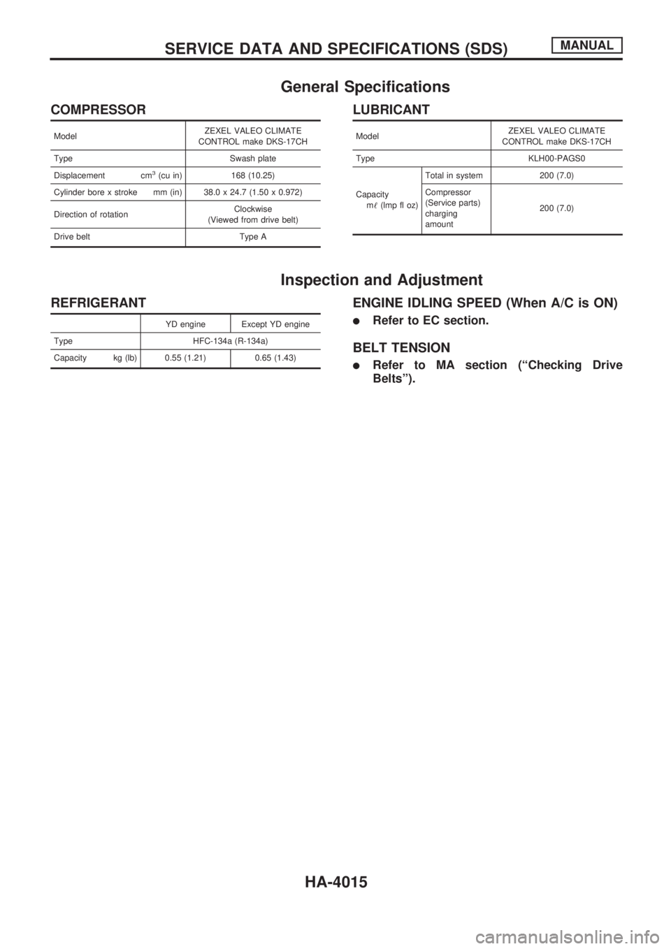
General Specifications
COMPRESSOR
ModelZEXEL VALEO CLIMATE
CONTROL make DKS-17CH
Type Swash plate
Displacement cm
3(cu in) 168 (10.25)
Cylinder bore x stroke mm (in) 38.0 x 24.7 (1.50 x 0.972)
Direction of rotationClockwise
(Viewed from drive belt)
Drive belt Type A
LUBRICANT
ModelZEXEL VALEO CLIMATE
CONTROL make DKS-17CH
Type KLH00-PAGS0
Capacity
m!(lmp fl oz)Total in system 200 (7.0)
Compressor
(Service parts)
charging
amount200 (7.0)
Inspection and Adjustment
REFRIGERANT
YD engine Except YD engine
Type HFC-134a (R-134a)
Capacity kg (lb) 0.55 (1.21) 0.65 (1.43)
ENGINE IDLING SPEED (When A/C is ON)
lRefer to EC section.
BELT TENSION
lRefer to MA section (ªChecking Drive
Beltsº).
SERVICE DATA AND SPECIFICATIONS (SDS)MANUAL
HA-4015
Page 121 of 229
Supplemental Restraint System (SRS) ªAIR
BAGº and ªSEAT BELT PRE-TENSIONERº
The Supplemental Restraint System such as ªAIR BAGº and ªSEAT BELT PRE-TENSIONERº used along
with a seat belt, helps to reduce the risk or severity of injury to the driver and front passenger in a frontal
collision. The SRS composition which is available to NISSAN MODEL D22 is as follows (The composition
varies according to the destination and optional equipment.):
Driver air bag module (located in the center of the steering wheel), front passenger air bag module (located
on the instrument panel on passenger side), seat belt pre-tensioner, a diagnosis sensor unit, warning lamp,
wiring harness and spiral cable.
WARNING:
lTo avoid rendering the SRS inoperative, which could increase the risk of personal injury or death
in the event of a collision which would result in air bag inflation, all maintenance must be per-
formed by an authorized NISSAN dealer.
lImproper maintenance, including incorrect removal and installation of the SRS, can lead to per-
sonal injury caused by unintentional activation of the system.
lDo not use electrical test equipment on any circuit related to the SRS unless instructed to in this
Service Manual. SRS wiring harnesses can be identified by yellow harness connector.
PRECAUTIONS AND PREPARATIONAUTO
HA-4016
Page 131 of 229
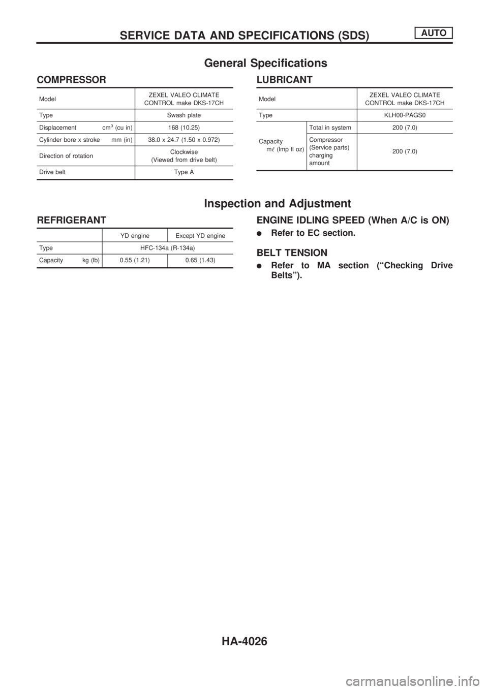
General Specifications
COMPRESSOR
ModelZEXEL VALEO CLIMATE
CONTROL make DKS-17CH
Type Swash plate
Displacement cm
3(cu in) 168 (10.25)
Cylinder bore x stroke mm (in) 38.0 x 24.7 (1.50 x 0.972)
Direction of rotationClockwise
(Viewed from drive belt)
Drive belt Type A
LUBRICANT
ModelZEXEL VALEO CLIMATE
CONTROL make DKS-17CH
Type KLH00-PAGS0
Capacity
m!(lmp fl oz)Total in system 200 (7.0)
Compressor
(Service parts)
charging
amount200 (7.0)
Inspection and Adjustment
REFRIGERANT
YD engine Except YD engine
Type HFC-134a (R-134a)
Capacity kg (lb) 0.55 (1.21) 0.65 (1.43)
ENGINE IDLING SPEED (When A/C is ON)
lRefer to EC section.
BELT TENSION
lRefer to MA section (ªChecking Drive
Beltsº).
SERVICE DATA AND SPECIFICATIONS (SDS)AUTO
HA-4026