oil pressure NISSAN PICK-UP 2003 Repair Manual
[x] Cancel search | Manufacturer: NISSAN, Model Year: 2003, Model line: PICK-UP, Model: NISSAN PICK-UP 2003Pages: 229, PDF Size: 8.89 MB
Page 103 of 229

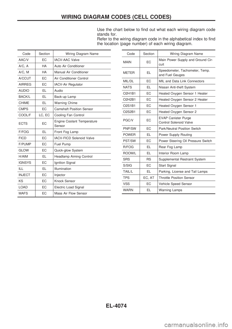
Use the chart below to find out what each wiring diagram code
stands for.
Refer to the wiring diagram code in the alphabetical index to find
the location (page number) of each wiring diagram.
Code Section Wiring Diagram Name
AAC/V EC IACV-AAC Valve
A/C, A HA Auto Air Conditioner
A/C, M HA Manual Air Conditioner
A/CCUT EC Air Conditioner Control
AIRREG EC IACV-Air Regulator
AUDIO EL Audio
BACK/L EL Back-up Lamp
CHIME EL Warning Chime
CMPS EC Camshaft Position Sensor
COOL/F LC, EC Cooling Fan Control
ECTS ECEngine Coolant Temperature
Sensor
F/FOG EL Front Fog Lamp
FICD EC IACV-FICD Solenoid Valve
F/PUMP EC Fuel Pump
GLOW EC Quick-glow System
H/AIM EL Headlamp Aiming Control
IGNSYS EC Ignition Signal
ILL EL Illumination
INJECT EC Injector
KS EC Knock Sensor
LOAD EC Electric Load Signal
MAFS EC Mass Air Flow SensorCode Section Wiring Diagram Name
MAIN ECMain Power Supply and Ground Cir-
cuit
METER ELSpeedometer, Tachometer, Temp.
and Fuel Gauges
MIL/DL EC MIL and Data Link Connectors
NATS EL Nissan Anti-theft System
O2H1B1 EC Heated Oxygen Sensor 1 Heater
O2H2B1 EC Heated Oxygen Sensor 2 Heater
O2S1B1 EC Heated Oxygen Sensor 1
O2S2B1 EC Heated Oxygen Sensor 2
PGC/V ECEVAP Canister Purge
Control Solenoid Valve
PNP/SW EC Park/Neutral Position Switch
POWER EL Power Supply Routing
PST/SW EC Power Steering Oil Pressure Switch
R/FOG EL Rear Fog Lamp
ROOM/L EL Interior Room Lamp
SRS RS Supplemental Restraint System
S/SIG EC Start Signal
TAIL/L EL Parking, License and Tail Lamps
TPS EC, AT Throttle Position Sensor
VSS EC Vehicle Speed Sensor
WARN EL Warning Lamps
WIRING DIAGRAM CODES (CELL CODES)
EL-4074
Page 130 of 229

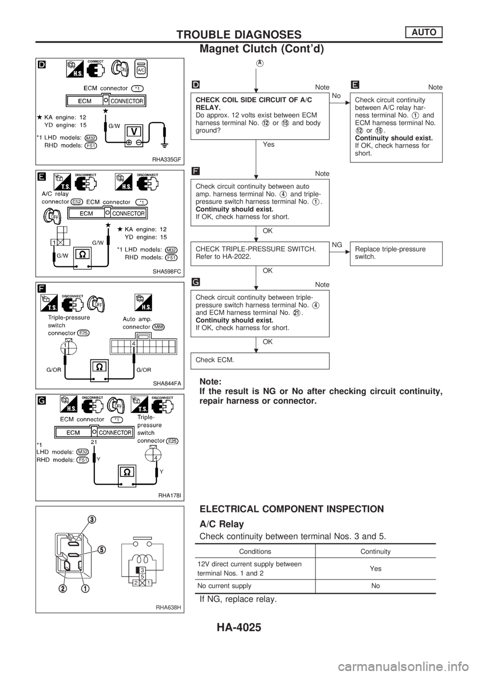
VA
NoteNote
CHECK COIL SIDE CIRCUIT OF A/C
RELAY.
Do approx. 12 volts exist between ECM
harness terminal No.
V12orV15and body
ground?
Yes
cNo
Check circuit continuity
between A/C relay har-
ness terminal No.
V1and
ECM harness terminal No.
V12orV15.
Continuity should exist.
If OK, check harness for
short.
Note
Check circuit continuity between auto
amp. harness terminal No.
V4and triple-
pressure switch harness terminal No.
V1.
Continuity should exist.
If OK, check harness for short.
OK
CHECK TRIPLE-PRESSURE SWITCH.
Refer to HA-2022.
OK
cNG
Replace triple-pressure
switch.
Note
Check circuit continuity between triple-
pressure switch harness terminal No.
V4and ECM harness terminal No.V21.
Continuity should exist.
If OK, check harness for short.
OK
Check ECM.
Note:
If the result is NG or No after checking circuit continuity,
repair harness or connector.
ELECTRICAL COMPONENT INSPECTION
A/C Relay
Check continuity between terminal Nos. 3 and 5.
Conditions Continuity
12V direct current supply between
terminal Nos. 1 and 2Yes
No current supply No
If NG, replace relay.
RHA335GF
SHA598FC
SHA844FA
RHA178I
RHA638H
.
.
. .
.
.
TROUBLE DIAGNOSESAUTO
Magnet Clutch (Cont'd)
HA-4025
Page 229 of 229

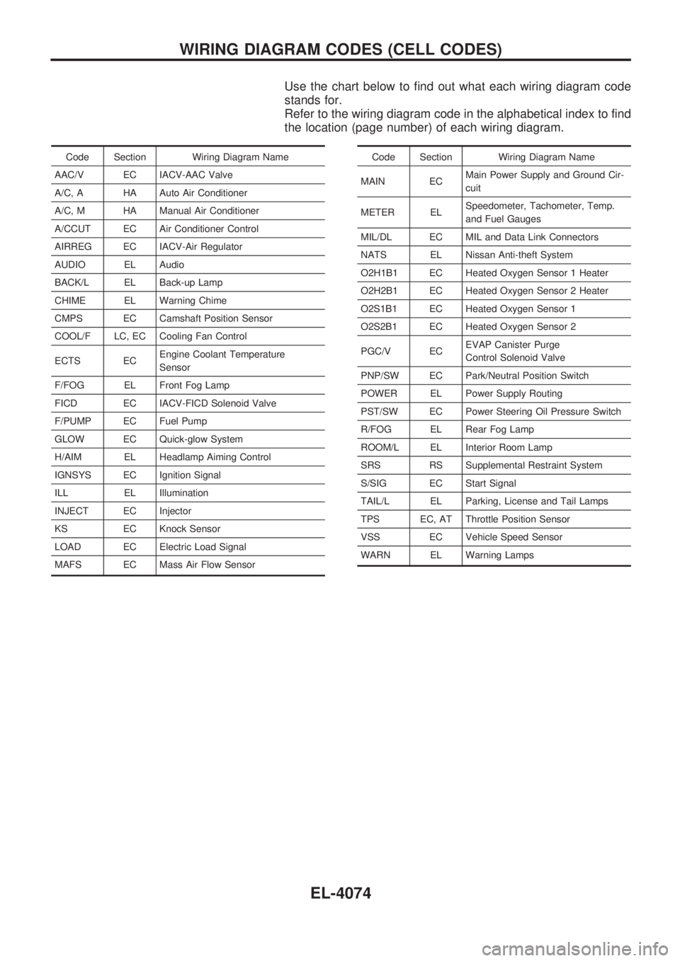
Use the chart below to find out what each wiring diagram code
stands for.
Refer to the wiring diagram code in the alphabetical index to find
the location (page number) of each wiring diagram.
Code Section Wiring Diagram Name
AAC/V EC IACV-AAC Valve
A/C, A HA Auto Air Conditioner
A/C, M HA Manual Air Conditioner
A/CCUT EC Air Conditioner Control
AIRREG EC IACV-Air Regulator
AUDIO EL Audio
BACK/L EL Back-up Lamp
CHIME EL Warning Chime
CMPS EC Camshaft Position Sensor
COOL/F LC, EC Cooling Fan Control
ECTS ECEngine Coolant Temperature
Sensor
F/FOG EL Front Fog Lamp
FICD EC IACV-FICD Solenoid Valve
F/PUMP EC Fuel Pump
GLOW EC Quick-glow System
H/AIM EL Headlamp Aiming Control
IGNSYS EC Ignition Signal
ILL EL Illumination
INJECT EC Injector
KS EC Knock Sensor
LOAD EC Electric Load Signal
MAFS EC Mass Air Flow SensorCode Section Wiring Diagram Name
MAIN ECMain Power Supply and Ground Cir-
cuit
METER ELSpeedometer, Tachometer, Temp.
and Fuel Gauges
MIL/DL EC MIL and Data Link Connectors
NATS EL Nissan Anti-theft System
O2H1B1 EC Heated Oxygen Sensor 1 Heater
O2H2B1 EC Heated Oxygen Sensor 2 Heater
O2S1B1 EC Heated Oxygen Sensor 1
O2S2B1 EC Heated Oxygen Sensor 2
PGC/V ECEVAP Canister Purge
Control Solenoid Valve
PNP/SW EC Park/Neutral Position Switch
POWER EL Power Supply Routing
PST/SW EC Power Steering Oil Pressure Switch
R/FOG EL Rear Fog Lamp
ROOM/L EL Interior Room Lamp
SRS RS Supplemental Restraint System
S/SIG EC Start Signal
TAIL/L EL Parking, License and Tail Lamps
TPS EC, AT Throttle Position Sensor
VSS EC Vehicle Speed Sensor
WARN EL Warning Lamps
WIRING DIAGRAM CODES (CELL CODES)
EL-4074