change time NISSAN PULSAR 1987 Workshop Manual
[x] Cancel search | Manufacturer: NISSAN, Model Year: 1987, Model line: PULSAR, Model: NISSAN PULSAR 1987Pages: 238, PDF Size: 28.91 MB
Page 16 of 238

16 Lubrication and Maintenance
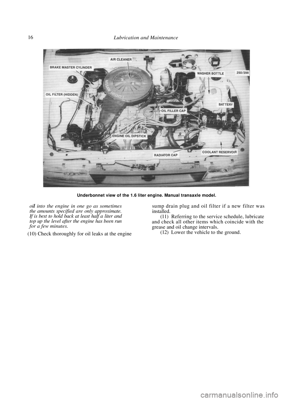
Underbonnet view of the 1.6 liter engine. Manual transaxle model.
oil into the engine in one go as sometimes
the amounts specified are only approximate.
If is best to hold back at least half a liter and
top up the level after the engine has been run
for a few minutes.
(10) Check thoroughly for oil leaks at the engine
sump drain plug and oil filter if a new filter was
installed.
(11) Referring to the service schedule, lubricate
and check all other items which coincide with the
grease and oil change intervals.
(12) Lower the vehicle to the ground.
Page 24 of 238

24 Wheels and Tires
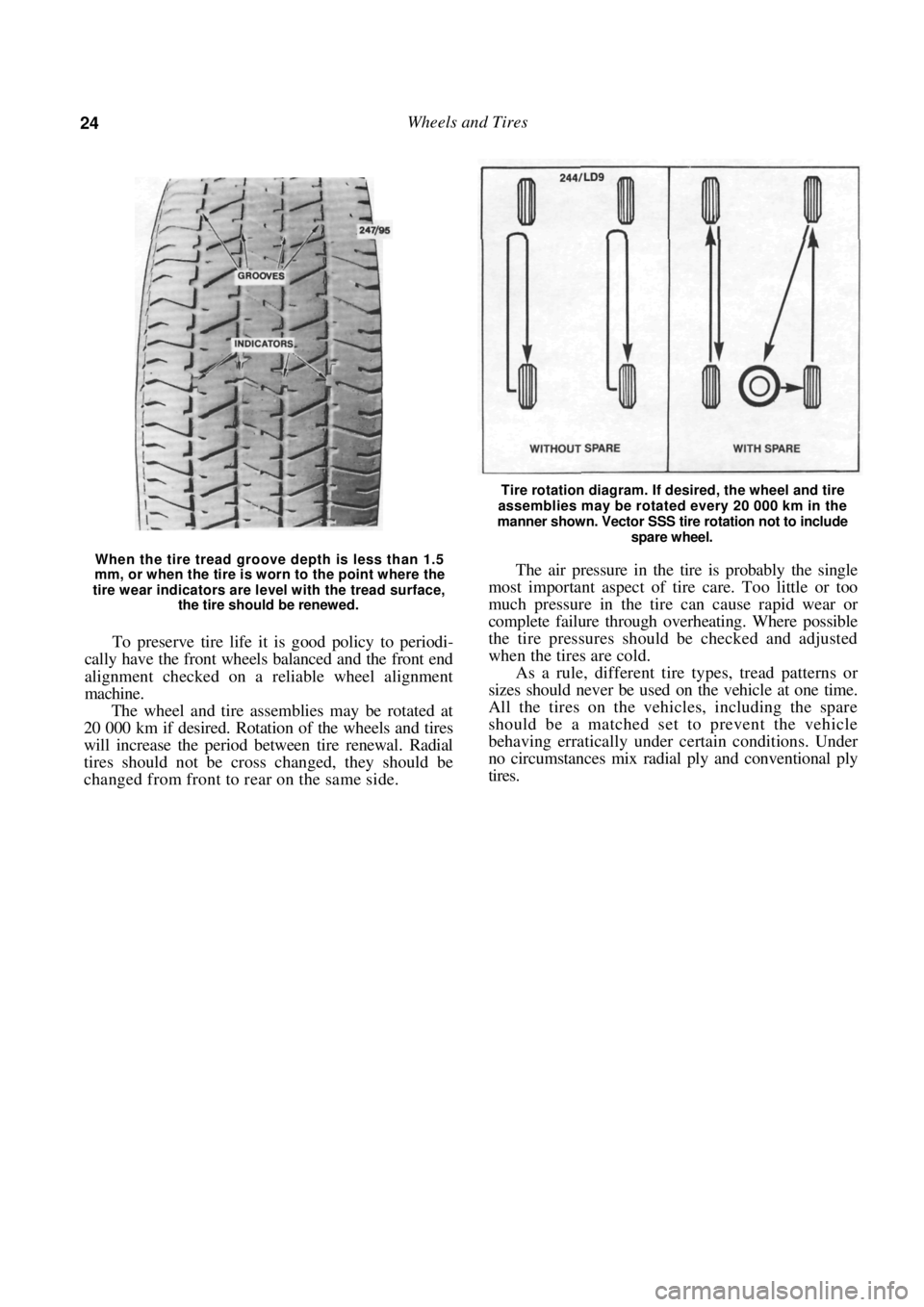
When the tire tread groove depth is less than 1.5
mm, or when the tire is worn to the point where the
tire wear indicators are level with the tread surface,
the tire should be renewed.
To preserve tire life it is good policy to periodi-
cally have the front wheels balanced and the front end
alignment checked on a reliable wheel alignment
machine.
The wheel and tire assemblies may be rotated at
20 000 km if desired. Rotation of the wheels and tires
will increase the period between tire renewal. Radial
tires should not be cross changed, they should be
changed from front to rear on the same side.
Tire rotation diagram. If desired, the wheel and tire
assemblies may be rotated every 20 000 km in the
manner shown. Vector SSS tire rotation not to include
spare wheel.
The air pressure in the tire is probably the single
most important aspect of tire care. Too little or too
much pressure in the tire can cause rapid wear or
complete failure through overheating. Where possible
the tire pressures should be checked and adjusted
when the tires are cold.
As a rule, different tire types, tread patterns or
sizes should never be used on the vehicle at one time.
All the tires on the vehicles, including the spare
should be a matched set to prevent the vehicle
behaving erratically under certain conditions. Under
no circumstances mix radial ply and conventional ply
tires.
Page 51 of 238

Engine 51
coolant temperature sensor and temperature sender
switch located in the thermostat housing.
(8) Remove the bolt securing the wiring clamp
to the rear of the manifold and maneuver the wiring
away from the cylinder head and the inlet manifold.
(9) Disconnect the throttle cable and on auto-
matic transaxle models, the kickdown cable from the
throttle body linkage. (10) Remove the bolls securing the throttle cable
bracket to the inlet manifold and place the bracket
and cable(s) to one side.
(11) Mark the fuel supply and return hoses to
ensure correct installation and disconnect the hoses
from the fuel rail or throttle body. Plug the hoses to
prevent the loss of fuel or the entry of dirt. (12) Mark the vacuum hoses connected to the
inlet manifold and throttle body to ensure correct
installation and disconnect the hoses. (13) Remove the nuts securing the engine pipe to
the exhaust manifold and separate the pipe from the
manifold. (14) Remove the oxygen sensor from the exhaust
manifold. Refer to the Fuel and Engine Management
section if necessary. (15) Remove the distributor and coil as described
in the Fuel and Engine Management section. (16) Disconnect the engine breather hoses from
the camshaft housing and cams haft housing top cover.
(17) Remove the bolts retaining the top cover to
the camshaft housing and remove the top cover. (18) Using an open end spanner, hold the cam-
shaft between the inlet and exhaust lobes of number
four cylinder and remove the camshaft timing gear
retaining bolt and the camshaft timing gear.
(19) Remove the bolts securing the camshaft
drive belt inner cover to the camshaft housing. (20) Loosen the cylinder head bolts in the reverse
order of the tightening sequence, backing off each bolt
a quarter turn then half a turn at a time until the bolts
are loose.
NOTE: Do not loosen the head bolts while
the engine is warm as distortion of the
cylinder head could result.
(21) Remove the cylinder head bolts and lift the
camshaft housing from the cylinder head. (22) Remove the cylinder head and gasket from
the cylinder block. Installation is a reversal of the removal procedure
with attention to the following points:
(1) Thoroughly clean the gasket surfaces of the
cylinder head, cylinder block and camshaft housing
and check all mating surfaces with a straight edge.
Ensure that all the oilways are clean and free of any
foreign material and lightly oil all operating parts with
engine oil.
(2) Install new gaskets throughout during
assem-
bly.
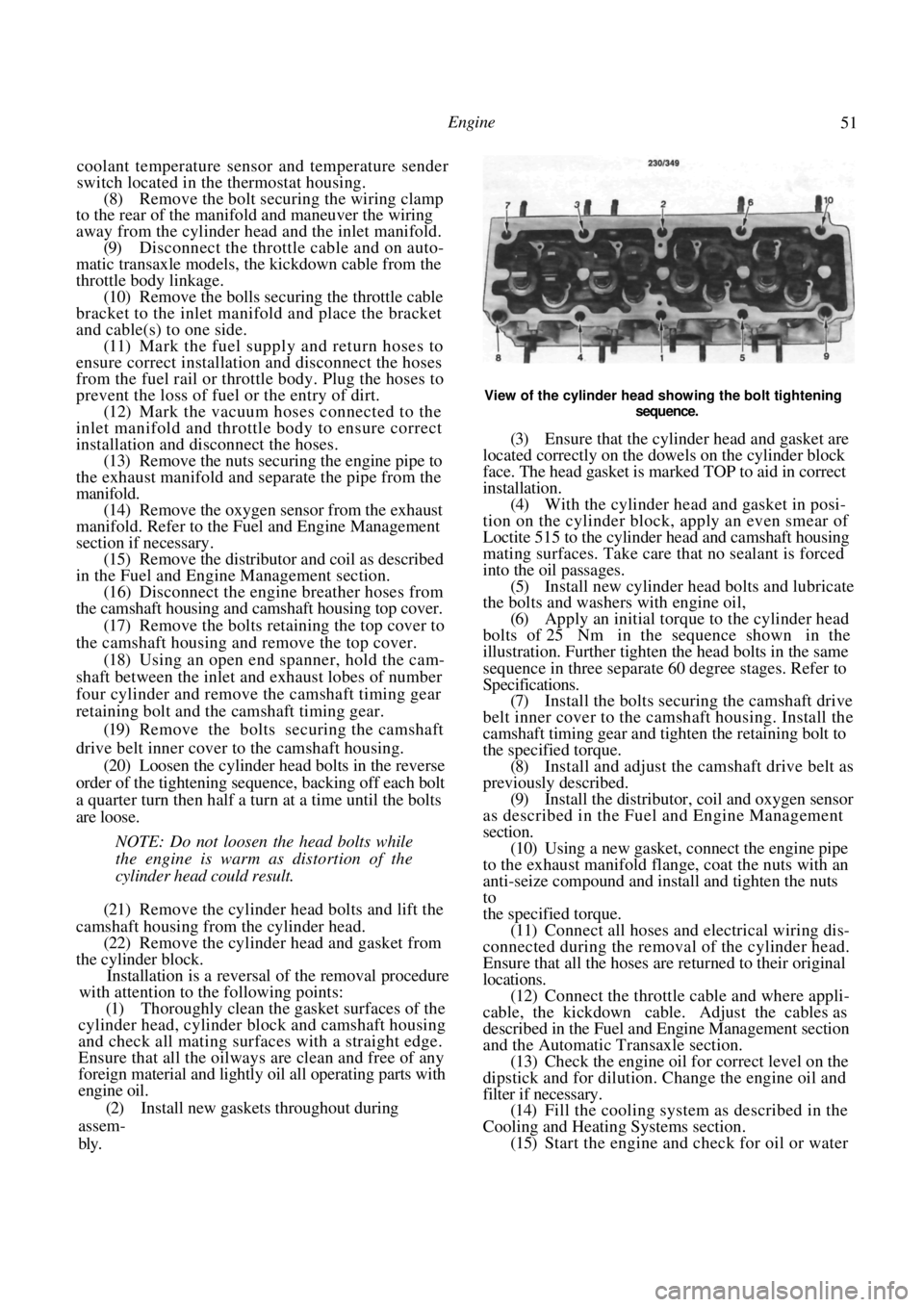
View of the cylinder head showing the bolt tightening
sequence.
(3) Ensure that the cylinde r head and gasket are
located correctly on the dowels on the cylinder block
face. The head gasket is marked TOP to aid in correct
installation. (4) With the cylinder head and gasket in posi-
tion on the cylinder block, apply an even smear of
Loctite 515 to the cylinder head and camshaft housing
mating surfaces. Take care that no sealant is forced
into the oil passages. (5) Install new cylinder head bolts and lubricate
the bolts and washers with engine oil,
(6) Apply an initial torque to the cylinder head
bolts of 25 Nm in the sequence shown in the
illustration. Further tighten the head bolts in the same
sequence in three separate 60 degree stages. Refer to
Specifications. (7) Install the bolts secur ing the camshaft drive
belt inner cover to the camshaft housing. Install the
camshaft timing gear and tighten the retaining bolt to
the specified torque. (8) Install and adjust the camshaft drive belt as
previously described. (9) Install the distributor, coil and oxygen sensor
as described in the Fuel and Engine Management
section.
(10) Using a new gasket, connect the engine pipe
to the exhaust manifold flange, coat the nuts with an
anti-seize compound and install and tighten the nuts
to
the specified torque. (11) Connect all hoses and electrical wiring dis-
connected during the removal of the cylinder head.
Ensure that all the hoses are returned to their original
locations. (12) Connect the throttle cable and where appli-
cable, the kickdown cable. Adjust the cables as
described in the Fuel and Engine Management section
and the Automatic Transaxle section. (13) Check the engine oil fo r correct level on the
dipstick and for dilution. Change the engine oil and
filter if necessary. (14) Fill the cooling system as described in the
Cooling and Heating Systems section. (15) Start the engine and check for oil or water