clock NISSAN PULSAR 1987 Workshop Manual
[x] Cancel search | Manufacturer: NISSAN, Model Year: 1987, Model line: PULSAR, Model: NISSAN PULSAR 1987Pages: 238, PDF Size: 28.91 MB
Page 10 of 238
10 General Information
If tools are to be stored for any length of time, it is
good policy to wipe them with an oily cloth.
Bladed screwdrivers should be checked for dam-
age to the tip. If necessary, the tip can be returned to
its original profile by careful grinding. Do not grind
screwdriver tips to a sharp point.
Hammer heads should be secure on their handles
and should be regularly checked for cracking or other
damage.
Chisels and punches should be checked for dam-
age or 'mushrooming' of the head. Any faults should
be rectified by grinding.
Hydraulic jacks should be regularly checked for
fluid leaks. Chassis stands and car ramps should be
checked for damage and cracks. Any equipment that
is suspect should not be used.
STORES
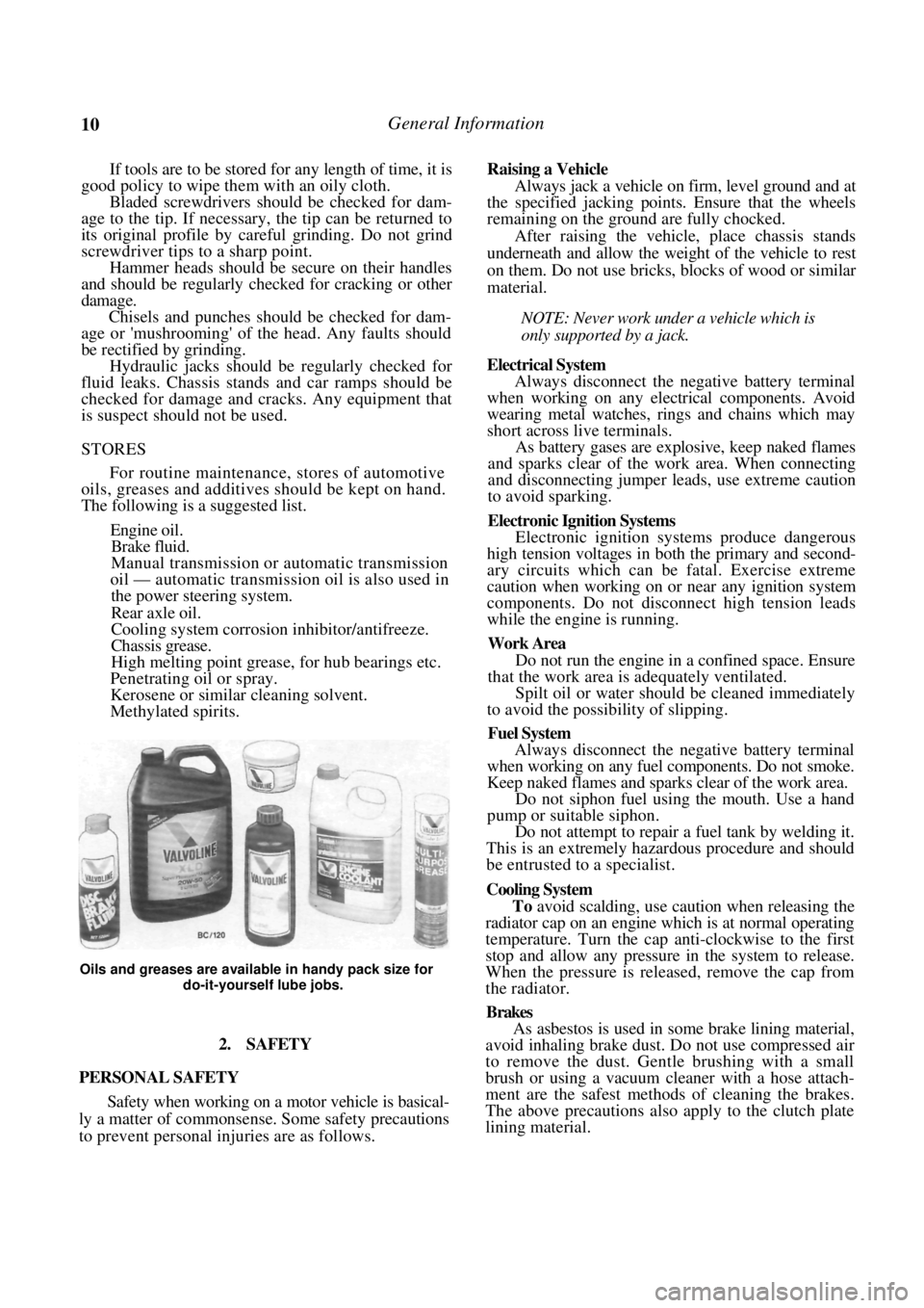
For routine maintenance, stores of automotive
oils, greases and additives should be kept on hand.
The following is a suggested list.
Engine oil.
Brake fluid.
Manual transmission or automatic transmission
oil — automatic transmission oil is also used in
the power steering system.
Rear axle oil.
Cooling system corrosion inhibitor/antifreeze.
Chassis grease.
High melting point grease, for hub bearings etc.
Penetrating oil or spray.
Kerosene or similar cleaning solvent.
Methylated spirits.
Oils and greases are available in handy pack size for
do-it-yourself lube jobs.
2. SAFETY
PERSONAL SAFETY
Safety when working on a motor vehicle is basical-
ly a matter of commonsense. Some safety precautions
to prevent personal in juries are as follows.
Raising a Vehicle
Always jack a vehicle on firm, level ground and at
the specified jacking points . Ensure that the wheels
remaining on the ground are fully chocked.
After raising the vehicle, place chassis stands
underneath and allow the weight of the vehicle to rest
on them. Do not use bricks, blocks of wood or similar
material.
NOTE: Never work under a vehicle which is
only supported by a jack.
Electrical System
Always disconnect the negative battery terminal
when working on any electrical components. Avoid
wearing metal watches, rings and chains which may
short across live terminals.
As battery gases are explosive, keep naked flames
and sparks clear of the work area. When connecting
and disconnecting jumper leads, use extreme caution
to avoid sparking.
Electronic Ignition Systems
Electronic ignition systems produce dangerous
high tension voltages in bo th the primary and second-
ary circuits which can be fatal. Exercise extreme
caution when working on or near any ignition system
components. Do not disconnect high tension leads
while the engine is running.
Work Area
Do not run the engine in a confined space. Ensure
that the work area is adequately ventilated.
Spilt oil or water should be cleaned immediately
to avoid the possibility of slipping.
Fuel System
Always disconnect the negative battery terminal
when working on any fuel components. Do not smoke.
Keep naked flames and sparks clear of the work area.
Do not siphon fuel using the mouth. Use a hand
pump or suitable siphon.
Do not attempt to repair a fuel tank by welding it.
This is an extremely hazardous procedure and should
be entrusted to a specialist.
Cooling System
To avoid scalding, use caution when releasing the
radiator cap on an engine wh ich is at normal operating
temperature. Turn the cap anti-clockwise to the first
stop and allow any pressure in the system to release.
When the pressure is released, remove the cap from
the radiator.
Brakes
As asbestos is used in some brake lining material,
avoid inhaling brake dust. Do not use compressed air
to remove the dust. Gentle brushing with a small
brush or using a vacuum cleaner with a hose attach-
ment are the safest methods of cleaning the brakes.
The above precautions also apply to the clutch plate
lining material.
Page 36 of 238
36 Roadside Trouble Shooting
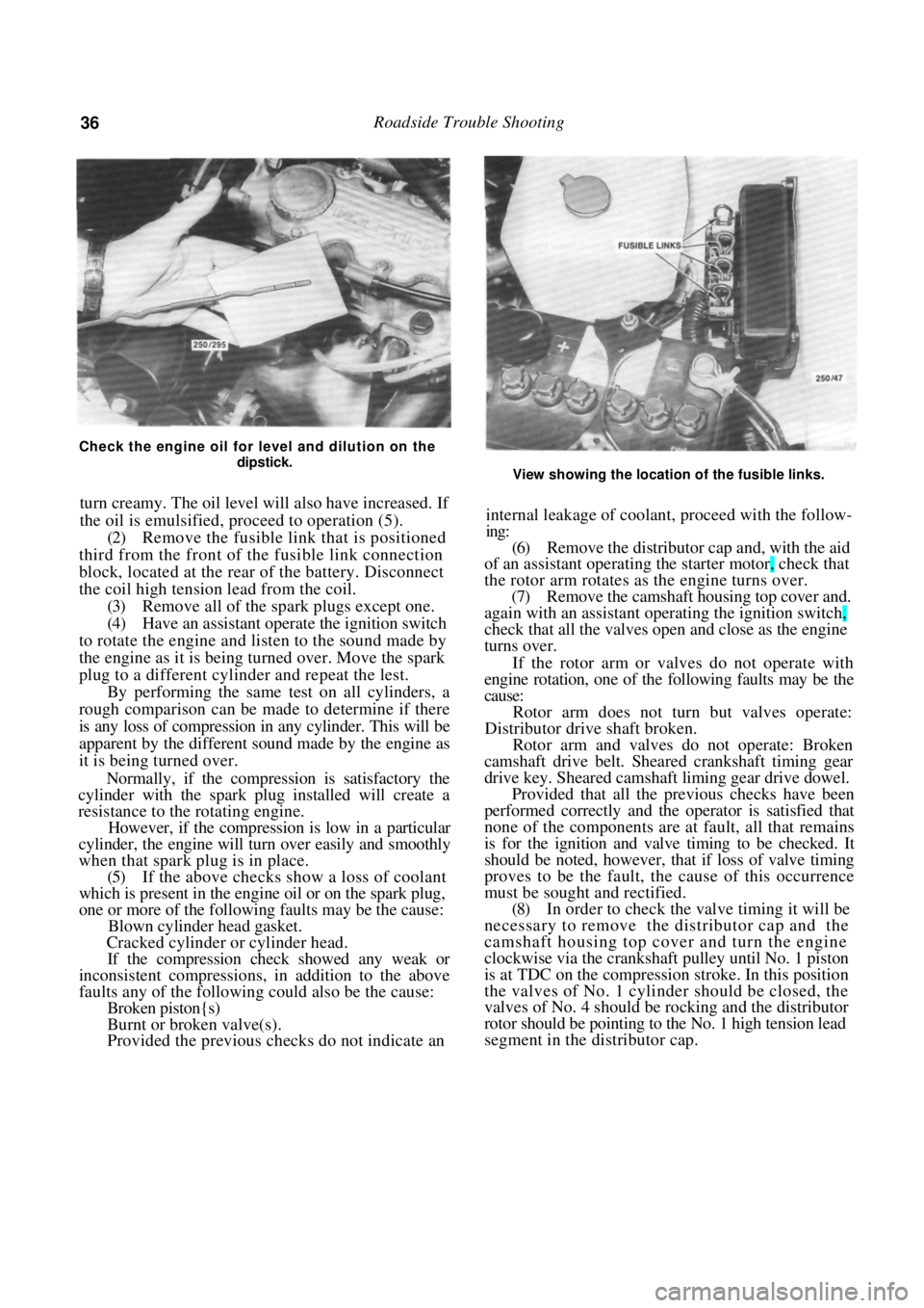
Check the engine oil for level and dilution on the dipstick.
turn creamy. The oil level will also have increased. If
the oil is emulsified, proceed to operation (5).
(2) Remove the fusible link that is positioned
third from the front of th e fusible link connection
block, located at the rear of the battery. Disconnect
the coil high tension lead from the coil. (3) Remove all of the spark plugs except one.
(4) Have an assistant operate the ignition switch
to rotate the engine and listen to the sound made by
the engine as it is being turned over. Move the spark
plug to a different cylinder and repeat the lest. By performing the same test on all cylinders, a
rough comparison can be made to determine if there
is any loss of compression in any cylinder. This will be
apparent by the different sound made by the engine as
it is being turned over.
Normally, if the compression is satisfactory the
cylinder with the spark plug installed will create a
resistance to the rotating engine.
However, if the compression is low in a particular
cylinder, the engine will tu rn over easily and smoothly
when that spark plug is in place.
(5) If the above checks show a loss of coolant
which is present in the engine oil or on the spark plug,
one or more of the following faults may be the cause:
Blown cylinder head gasket.
Cracked cylinder or cylinder head.
If the compression check showed any weak or
inconsistent compressions, in addition to the above
faults any of the following could also be the cause:
Broken piston{s)
Burnt or broken valve(s).
Provided the previous checks do not indicate an
View showing the location of the fusible links.
internal leakage of coolant, proceed with the follow-
ing:
(6) Remove the distributor cap and, with the aid
of an assistant operating th e starter motor, check that
the rotor arm rotates as the engine turns over. (7) Remove the camshaft hous ing top cover and.
again with an assistant operating the ignition switch,
check that all the valves open and close as the engine
turns over.
If the rotor arm or valves do not operate with
engine rotation, one of the following faults may be the
cause:
Rotor arm does not turn but valves operate:
Distributor drive shaft broken.
Rotor arm and valves do not operate: Broken
camshaft drive belt. Sheare d crankshaft timing gear
drive key. Sheared camshaft liming gear drive dowel.
Provided that all the previous checks have been
performed correctly and the operator is satisfied that
none of the components are at fault, all that remains
is for the ignition and valve timing to be checked. It
should be noted, however, that if loss of valve timing
proves to be the fault, th e cause of this occurrence
must be sought and rectified.
(8) In order to check the valve timing it will be
necessary to remove the distributor cap and the
camshaft housing top cover and turn the engine
clockwise via the crankshaft pulley until No. 1 piston
is at TDC on the compression stroke. In this position
the valves of No. 1 cylinder should be closed, the
valves of No. 4 should be rocking and the distributor
rotor should be pointing to the No. 1 high tension lead
segment in the distributor cap.
Page 62 of 238
Engine
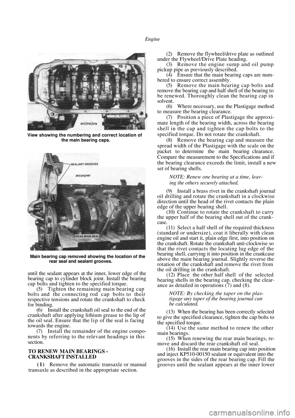
Main bearing cap removed showing the location of the rear seal and sealant grooves.
until the sealant appears at the inner, lower edge of the
bearing cap to cylinder block joint. Install the bearing
cap bolts and tighten to the specified torque.
(5) Tighten the remaining main bearing cap
bolts and the connecting rod cap bolts to their
respective tensions and rotate the crankshaft to check
for binding. (6) Install the crankshaft oil seal to the end of the
crankshaft after applying lithium grease to the lip of
the oil seal. Ensure that the l i p of the seal is facing
towards the engine.
(7) Install the remainder of the engine compo-
nents by referring to the relevant headings in this
section.
TO RENEW MAIN BEARINGS -
CRANKSHAFT INSTALLED
(1) Remove the automatic transaxle or manual
transaxle as described in the appropriate section.
(2) Remove the flywheel/drive plate as outlined
under the Flywheel/Drive Plate heading. (3) Remove the engine sump and oil pump
pickup pipe as previously described. (4) Ensure that the main bearing caps are num-
bered to ensure correct assembly. (5) Remove the main bearing cap bolts and
remove the bearing cap and half shell of the bearing to
be renewed. Thoroughly clean the bearing cap in
solvent. (6) Where necessary, use the Plastigage method
to measure the bearing clearance.
(7) Position a piece of Plastigage the approxi-
mate length of the bearing width, across the bearing
shell in the cap and tigh ten the cap bolts to the
specified torque. Do not rotate the crankshaft. (8) Remove the bearing cap and measure the
spread width of the Plastigage with the scale on the
packet to determine the main bearing clearance.
Compare the measurement to the Specifications and if
the bearing clearance exceeds the limit, install a new
set of bearing shells.
NOTE: Renew one bearing at a time, leav-
ing the others securely attached.
(9) Install a brass rivet in the crankshaft journal
oil drilling and rotate the crankshaft in a clockwise
direction until the head of the rivet contacts the plain
edge of the upper bearing shell. (10) Continue to rotate the crankshaft to carry
the upper half of the bearing shell out of the crank-
case.
(11) Select a half shell of the required thickness
(standard or undersize), coat it liberally with clean
engine oil and start it, plai n edge first, into position on
the crankshaft. Rotate the crankshaft anti-clockwise so
that the rivet contacts the locating lug edge of the
bearing shell, carrying it into position in the crankcase
above the main bearing journal. Slightly reverse the
rotation of the crankshaft and remove the rivet from
the oil drilling in the crankshaft. (12) Place the other half shell of the selected
bearing shells in the bear ing cap. checking the clear-
ance as detailed in operations (7) and (8).
NOTE: By checking the taper on the plas-
tigage any taper of the bearing journal can
be calculated.
(13) When the bearing has been correctly selected
to give the specified clearance, tighten the cap bolts to
the specified torque. (14) Use the same method to renew the other
main bearings. (15) When renewing the rear main bearings, re-
move and discard the rear crankshaft oil seal. (16) Install the rear main bearing cap into position
and inject KP510-00150 sealant or equivalent into the
grooves in the sides of the rear bearing cap. Fill the
grooves until the sealant a ppears at the inner lower
View showing the numbering and correct location of
the main bearing caps.
Page 70 of 238
70 Cooling and Heating Systems
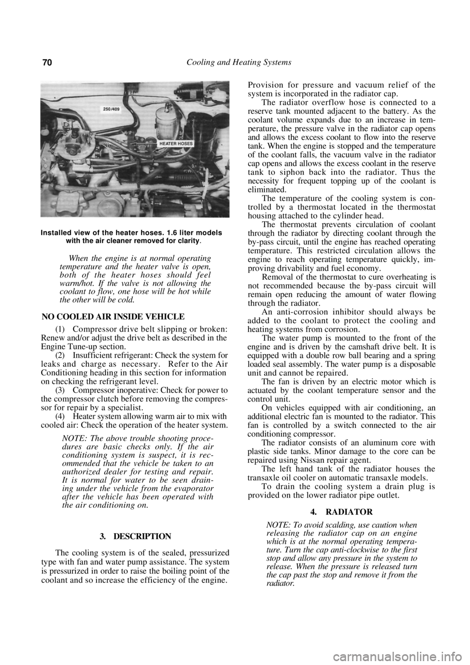
Installed view of the heater hoses. 1.6 liter models with the air cleaner removed for clarity
.
When the engine is at normal operating
temperature and the heater valve is open,
both of the heater hoses should feel
warm/hot. If the valve is not allowing the
coolant to flow, one hose will be hot while
the other will be cold.
NO COOLED AIR INSIDE VEHICLE
(1) Compressor drive belt slipping or broken:
Renew and/or adjust the drive belt as described in the
Engine Tune-up section.
(2) Insufficient refrigerant: Check the system for
leaks and charge as necessary. Refer to the Air
Conditioning heading in th is section for information
on checking the refrigerant level. (3) Compressor inoperative: Check for power to
the compressor clutch before removing the compres-
sor for repair by a specialist. (4) Heater system allowing warm air to mix with
cooled air: Check the operation of the heater system.
NOTE: The above trouble shooting proce-
dures are basic checks only. If the air
conditioning system is suspect, it is rec-
ommended that the vehicle be taken to an
authorized dealer for testing and repair.
It is normal for water to be seen drain-
ing under the vehicle from the evaporator
after the vehicle has been operated with
the air conditioning on.
3. DESCRIPTION
The cooling system is of the sealed, pressurized
type with fan and water pump assistance. The system
is pressurized in order to raise the boiling point of the
coolant and so increase the efficiency of the engine.
Provision for pressure a nd vacuum relief of the
system is incorporated in the radiator cap.
The radiator overflow hose is connected to a
reserve tank mounted adjacent to the battery. As the
coolant volume expands due to an increase in tem-
perature, the pressure valve in the radiator cap opens
and allows the excess coolant to flow into the reserve
tank. When the engine is stopped and the temperature
of the coolant falls, the vacuum valve in the radiator
cap opens and allows the excess coolant in the reserve
tank to siphon back into the radiator. Thus the
necessity for frequent topping up of the coolant is
eliminated.
The temperature of the cooling system is con-
trolled by a thermostat located in the thermostat
housing attached to the cylinder head.
The thermostat prevents circulation of coolant
through the radiator by directing coolant through the
by-pass circuit, until the engine has reached operating
temperature. This restricted circulation allows the
engine to reach operating temperature quickly, im-
proving drivability and fuel economy.
Removal of the thermostat to cure overheating is
not recommended because th e by-pass circuit will
remain open reducing the amount of water flowing
through the radiator.
An anti-corrosion inhibitor should always be
added to the coolant to protect the cooling and
heating systems from corrosion.
The water pump is mounted to the front of the
engine and is driven by the camshaft drive belt. It is
equipped with a double row ball bearing and a spring
loaded seal assembly. The water pump is a disposable
unit and cannot be repaired.
The fan is driven by an electric motor which is
actuated by the coolant temperature sensor and the
control unit.
On vehicles equipped with air conditioning, an
additional electric fan is m ounted to the radiator. This
fan is controlled by a sw itch connected to the air
conditioning compressor.
The radiator consists of an aluminum core with
plastic side tanks. Minor damage to the core can be
repaired using Nissan repair agent.
The left hand tank of the radiator houses the
transaxle oil cooler on automatic transaxle models.
To drain the cooling system a drain plug is
provided on the lower radiator pipe outlet.
4. RADIATOR
NOTE: To avoid scalding, use caution when
releasing the radiator cap on an engine
which is at the normal operating tempera-
ture. Turn the cap anti-clockwise to the first
stop and allow any pressure in the system to
release. When the pressure is released turn
the cap past the stop and remove it from the
radiator.
Page 79 of 238
Cooling and Heating Systems 79
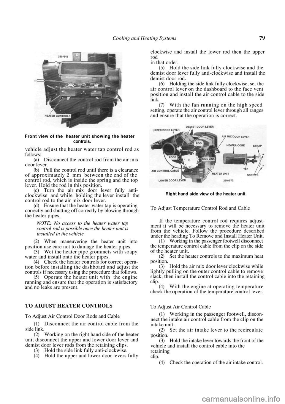
Front view of the heater unit showing the heater controls.
vehicle adjust the heater water tap control rod as
follows:
(a) Disconnect the control rod from the air mix
door lever.
(b) Pull the control rod un til there is a clearance
of approximately 2 mm between the end of the
control rod, which is inside the spring and the top
lever. Hold the rod in this position.
(c) Turn the air mix door lever fully anti-
clockwise and while holding the lever install the
control rod to the air mix door lever. (d) Ensure that the heater water tap is operating
correctly and shutting off correctly by blowing through
the heater pipes.
NOTE: No access to the heater water tap
control rod is possible once the heater unit is
installed in the vehicle.
(2) When maneuvering the heater unit into
position use care not to damage the heater pipes. (3) Wet the heater pipe grommets with soapy
water and install onto the heater pipes. (4) Check the heater controls for correct opera-
tion before installing the dashboard and adjust the
controls if necessary using the procedure that follows. (5) Operate the heater unit with the engine
running and ensure that the operation is satisfactory
and no leaks are present. clockwise and install the lower rod then the upper
rod
in that order.
(5)
Hold the side link fully clockwise and the
demist door lever fully anti-clockwise and install the
demist door rod. (6) Holding the side link fully clockwise, set the
air control lever on the dashboard to the face vent
position and install the air control cable to the side
link. (7) With the fan running on the high speed
setting, operate the air cont rol lever through all ranges
and ensure that the operation is correct.
Right hand side view of the heater unit.
To Adjust Temperature Control Rod and Cable
If the temperature control rod requires adjust-
ment it will be necessary to remove the heater unit
from the vehicle. Follow the procedure described
under the heading To Remove and Install Heater Unit.
(1) Working in the passenger footwell disconnect
the temperature control cable from the clip on the side
of the heater unit. (2) Set the heater controls to the maximum heat
position. (3) Hold the air mix door lever clockwise while
lightly pulling on the outer control cable to remove
slack, then install the control cable into the retaining
clip.
(4) With the engine at operating temperature
check the operation of the temperature control lever.
TO ADJUST HEATER CONTROLS
To Adjust Air Control Door Rods and Cable
(1) Disconnect the air control cable from the
side link. (2) Working on the right hand side of the heater
unit disconnect the upper and lower door lever and
demist door lever rods from the retaining clips.
(3) Hold the side link fully anti-clockwise.
(4) Hold the upper and lower door levers fully To Adjust Air Control Cable
(1)
Working in the passeng er footwell, discon-
nect the intake air control cable from the clip on the
intake unit. (2) Set the air intake lever to the recirculate
position. (3) Hold the intake lever to wards the front of the
vehicle and install the control cable into the
retaining
clip.
(4) Check the operation of the air intake control.
Page 82 of 238

82
FUEL AND ENGINE MANAGEMENT
CAUTION: To prevent severe electrical shock, extreme care must be taken when
working on or near the electronic ignition system as dangerous high tension voltages
are produced in both the primary and secondary circuits. See the text fo\
r
precautionary notes.
SPECIFICATIONS
FUEL INJECTION
Type:
1.6 liter engine .................................. Single point
1.8 liter engine................................... Multi point
FUEL PUMP
Type ................................................................ Electric
Pressure at idle:
1.6 liter engine ..................................... 62-90 kPa
1.8 liter engine ................................ 190-230 kPa
FUEL FILTER
Type ................................................ Inline, disposable
AIR FILTER
Type ................................... Disposable paper element
DISTRIBUTOR
Make ........................................................ Delco Remy
Advance contro l .......................................... Electronic
Rotation of rotor .................................. Anti-clockwise
Firing order....................................................1 -3-4-2
ADJUSTMENTS
Base idle speed ..................................... 550-650 rpm
Ignition timing.......................................... 10° BTDC
TORQUE WRENCH SETTINGS
Throttle body nuts.......................................... 10 Nm
*Throttle body bolts ........................................ 12 Nm
*Fuel hose fittings............................................ 35 Nm
Fuel rail bolts ....................................................8 Nm
Fuel tank drain plug ........................................ 24 Nm
Coolant temperature sensor ............................ 12 Nm
Oxygen sensor .................................................. 40 Nm
MAT sensor..................................................... 14 Nm
*1.6 liter engine
l . 8 liter engine
1. FUEL AND ENGINE MANAGEMENT
TROUBLE SHOOTING
NOTE: The following Trouble Shooting pro-
cedures are basic checks only. If these pro-
cedures fail to locate the fault, refer to the
System Diagnosis and Adjustments heading
for more thorough testing.
Prior to performing any of the following
operations, refer to the Service Precautions
and Procedures heading.
ENGINE WILL NOT START OR HARD TO
START
(1) Water in the fuel: Dr ain the fuel from the
system and renew the fuel filter.
(2) Fault in the power supply: Check the battery,
fusible links and fuses. Check for clean, secure con-
nections, particularly the earth connections. Check the
EG1 and fuel pump relays.
NOTE: If the fuel pump relay fails, power
will be supplied to the fuel pump via the oil
pressure switch. When starting the engine,
Check that the MAP sensor hose is not blocked or split
and ensure that all electrical connections are clean and
secure.
Page 181 of 238

Brakes 181
chor plate to the steering knuckle and slide the caliper
off the brake disc. Suspend the caliper clear of the
work area using wire or cord.
(3) Suitably mark the location of the disc in
relation to the hub.
(4) Slide the disc off the hub. If the disc is
difficult to remove, install two M8 x 1.25 mm bolts in
the disc and by alternatively tightening the bolts,
remove the disc.
Do not use a hammer to remove the disc.
Installation is a reversal of the removal procedure
ensuring that the mating face s of the disc and hub are
clean and free from burrs and that the marks made on
removal are aligned.
To Inspect
(1) Inspect the machined faces of the disc for
scores, cracks, wear and signs of overheating. (2) Using a micrometer, measure the thickness
of the disc at several positi ons around the face of the
disc. Renew the disc if the minimum thickness is
below Specifications.
Inspect the brake discs for scoring and wear.
(3) If the disc thickness is satisfactory but the
disc is scored, machine equal amounts from the
machined face on each side of the disc, to restore the
serviceability of the disc.
NOTE: Disc machining is best entrusted to
a reliable brake specialist who can advise on
disc serviceability.
6. REAR DISC BRAKES
Special Equipment Required:
To Check Disc Runout — Dial gauge
To Check Disc Thickness — Micrometer
TO CHECK AND RENEW BRAKE PADS
( 1 ) Raise the rear of the vehicle and place it on
chassis stands. Remove the rear wheels.
Renew the rear brake pads if the friction material is less
than 2 mm thick.
(2) Inspect the brake pads on both sides of the
vehicle. If the friction material on one or more of the
pads is less than 2 mm thick or contaminated with
fluid or grease, renew the brake pad as a set as follows.
NOTE: If the brake pads are contaminated
trace and rectify the cause prior to installing
the new set of pads.
(3) Drain approximately two thirds of the brake
fluid from the master cylinder reservoir. This can be
done by loosening the bleeder valve on the caliper and
allowing the fluid to drai n into a container. Discard
this fluid.
NOTE: Do not drain all the fluid from the
reservoir otherwise it will be necessary to
bleed the hydraulic system. The fluid is
drained from the reservoir to prevent over-
flow when the caliper piston is pushed back
into the caliper bore to facilitate pad re-
newal.
(4) Remove the guide bolts and lift the caliper
body clear of the disc.
NOTE: Do not allow the caliper to hang on
the brake hose.
(5) Noting the installed positions, remove the
brake pads, shims and spring clips from the anchor
plate.
(6) Using a pair of long nosed pliers with the
nose located in the recesses of the piston, rotate the
piston clockwise to retract it into the cylinder body.
Align the recesses between the brake pad retaining
lugs on the caliper body. Refer to the illustration. (7) If necessary, check the disc runout and
thickness as described under the Brake Disc heading.
(8) Ensure that the guide bolts move freely in the
caliper body and that the dust boots are in good
condition.
Page 183 of 238
Brakes 183
To Dismantle
(1) Raise the rear of the vehicle and place it on
chassis stands. Remove the relevant rear wheel.
(2) Remove the brake hose retaining bolt from
the caliper body and plug the hose to prevent the loss
of fluid and the ingress of dirt. (3) Remove the handbrake cable bracket retain-
ing bolt and disconnect the handbrake cable from the
cam lever.
(4) Remove the guide bolts and slide the caliper
body off the pads. (5) Using a pair of long nose pliers with the nose
located in the recesses of the piston, rotate the piston
anticlockwise to remove it from the caliper body.
(6) Remove the dust cover retaining clip and dust
cover. Discard the dust cover. (7) Using a thin blunt probe, preferably made
from wood or plastic, remove and discard the piston
seal from the groove in the caliper bore. (8) Using internal snap ring pliers, remove the
snap ring from the caliper bore. (9) Withdraw the spring cover, spring, key plate,
pushrod and link from the caliper bore. Do not mix
these components from the left and right hand sides as
they differ. (10) Remove and discard the O ring from the
pushrod. (11) Remove the spring, nut and washer from the
cam lever. Remove the cam lever and cam from the
caliper body. (12) Remove the cam seal from the caliper using a
screwdriver.
(13) Clean all the caliper components in methy-
lated spirits and arrange the components in order on a
clean dry surface to aid assembly.
To Inspect
(1) Inspect the caliper bore and piston for pit-
ting, wear or damage. Renew the caliper assembly or
piston if damage is evident.
NOTE: Slight rust spots in the caliper bore
may be removed with fine emery paper. The
piston must not be polished as the plated
surface will be damaged.
(2) Inspect the guide bolts for wear or damage
and renew as necessary.
(3) Inspect the threads of the pushrod for wear or
damage and renew as necessary. (4) Inspect the nut inside the piston for wear,
damage and security. Renew the piston if any damage
is evident. (5) Inspect the cam for wear, damage or pitting,
renew as necessary. (6) Inspect the cam bearing in the caliper body
for wear, damage or pitting and renew the seal and
bearing as necessary. (7) Inspect the guide bolt rubbers for deteriora-
tion, wear or damage. Renew as required. To Assemble
(1)
Lubricate the cam bearing with multipurpose
grease and install the seal. (2) Install the cam and cam lever to the
caliper
body. Install the cam lever spring, washer and nut, and
tighten the nut to the specified torque. (3) Install a new O ring to the pushrod and
install
the link, pushrod, key plate, spring and spring cover to
the caliper body. The key plate must engage the caliper
body. Secure the assembly with the snap ring. (4) Dip a new piston seal in clean hydraulic brake
fluid. Insert the seal into the groove in the caliper bore
ensuring that the seal is correctly seated and not
twisted. (5) Install a new dust cover to the piston prior
to
installing the piston to the caliper bore.
(6) Coat the piston and caliper bore with clean
hydraulic brake fluid and using long nose pliers rotate
the piston clockwise into the caliper bore. (7) Locate the dust seal in the groove of the
caliper body and install the retaining clip.
(8) Lubricate the guide bolts using a suitable
grease. Install the caliper body and tighten the guide
bolts to the specified torque. (9) Replenish the master cylinder reservoir with
the recommended fluid and bleed the brakes as
described under the Hydraulic System heading. (10) Install the rear wheel and lower the vehicle to
the ground. (11) Road test the vehicle and check for correct
brake operation.
BRAKE DISC
To Check Runout
(1) Raise the rear of the vehicle and support it on
chassis stands. Remove the relevant rear wheel.
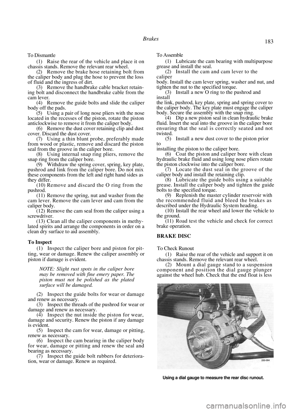
(2) Mount a dial gauge stand to a suspension
component and position the dial gauge plunger
against the wheel hub. Check that the end float is less
Using a dial gauge to measure the rear disc runout.
Page 211 of 238
Electrical System 211
When using an aiming board, position the
vehicle five meters from and square to the aiming
board. Gently rock the vehi cle and allow the suspen-
sion to stabilize. Mark a reference line on the board to
correspond with the horizontal centre line of the
headlamp low beam bulbs. Mark two reference lines on the board to
correspond with the vertical centre lines of
the
headlamp low beam bulbs. Switch on the headlamps and select low
beam. Adjust the headlamps by turning the adjust-
ing screws located at the rear of the headlamp
assemblies. Adjust the headlamps to comply with local
regulations. As a guide, adjust the lamps so that the
low beam pattern strikes the aiming board with the
horizontal cut off point 50 mm below the headlamp
bulb horizontal centre line and the point where the
beam raises from the horizontal is on the headlamp
low beam bulb vertical centre line.
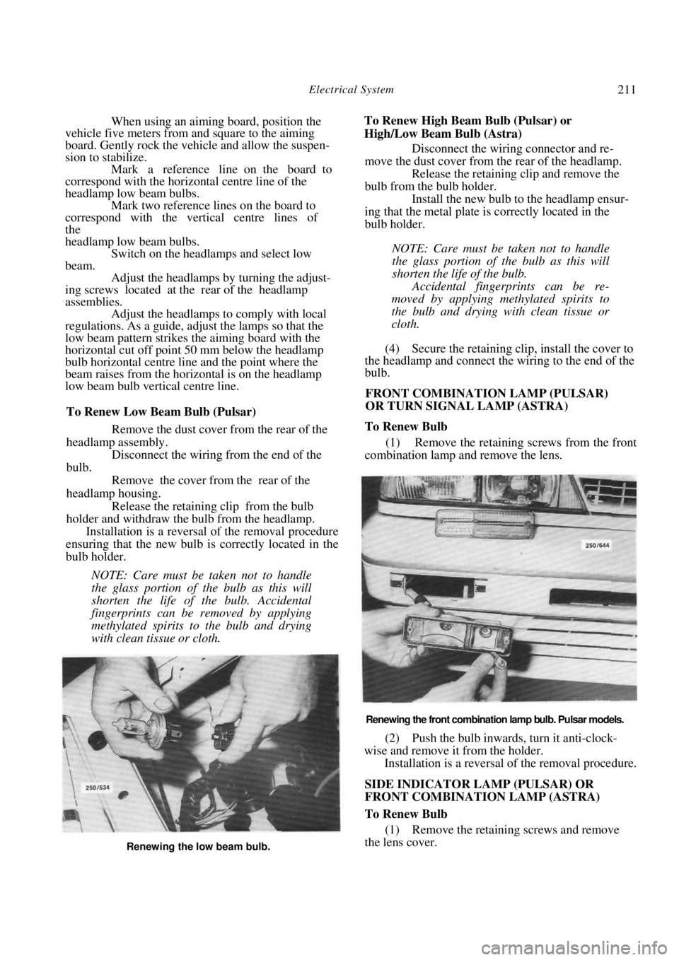
To Renew Low Beam Bulb (Pulsar)
Remove the dust cover from the rear of the
headlamp assembly.
Disconnect the wiring from the end of the
bulb.
Remove the cover from the rear of the
headlamp housing. Release the retaining clip from the bulb
holder and withdraw the bulb from the headlamp. Installation is a reversal of the removal procedure
ensuring that the new bulb is correctly located in the
bulb holder.
NOTE: Care must be taken not to handle
the glass portion of the bulb as this will
shorten the life of the bulb. Accidental
fingerprints can be removed by applying
methylated spirits to the bulb and drying
with clean tissue or cloth.
To Renew High Beam Bulb (Pulsar) or
High/Low Beam Bulb (Astra) Disconnect the wiring connector and re-
move the dust cover from the rear of the headlamp. Release the retaining clip and remove the
bulb from the bulb holder. Install the new bulb to the headlamp ensur-
ing that the metal plate is correctly located in the
bulb holder.
NOTE: Care must be taken not to handle
the glass portion of the bulb as this will
shorten the life of the bulb.
Accidental fingerprints can be re-
moved by applying methylated spirits to
the bulb and drying with clean tissue or
cloth.
(4) Secure the retaining clip, install the cover to
the headlamp and connect the wiring to the end of the
bulb.
FRONT COMBINATION LAMP (PULSAR)
OR TURN SIGNAL LAMP (ASTRA)
To Renew Bulb
(1) Remove the retaining screws from the front
combination lamp and remove the lens.
Renewing the front combination lamp bulb. Pulsar models.
(2) Push the bulb inwards, turn it anti-clock-
wise and remove it from the holder. Installation is a reversal of the removal procedure.
SIDE INDICATOR LAMP (PULSAR) OR
FRONT COMBINATION LAMP (ASTRA)
To Renew Bulb
(1) Remove the retaining screws and remove
the lens cover.
Renewing the low beam bulb.
Page 212 of 238

212 Electrical System
Renewing the side indicator lamp bulb.
(2) Push the bulb inwards, turn it anti-clockwise
and remove it from the holder.
Installation is a reversal of the removal procedure.
REAR COMBINATION LAMP
To Renew Bulb
(1) Working inside the luggage compartment,
remove the combination lamp trim cover.
Renewing the rear combination lamp bulb.
Remove the desired bulb holder from the
combination lamp by twisting it anti-clockwise and
withdrawing it from the lamp body.
Push the bulb inwards, turn it anti-clockwise
and remove it from the holder.
Installation is a reversal of the removal procedure.
NUMBER PLATE LAMP
To Renew Bulb
(1) On Pulsar models, proceed as follows:
Carefully prise the number plate lamp unit
from the rear bumper bar. Remove the retaining screws and remove
the lens cover and lens.
Renewing the number plate lamp bulb.
(2) On Astra models, remove the retaining
screws and remove the lamp unit from the bumper
bar. Remove the bulb holder from the lamp unit.
(3) Remove the bulb from the lamp.
Installation is a reversal for the removal procedure.
COURTESY LAMP
To Renew Bulb
Turn the lamp lens anti-clockwise and lower
it from the lamp. Grip and remove the bulb from between the
bulb contacts.
Renewing the courtesy lamp bulb.
Installation is a reversal of the removal procedure
with attention to the following points:
Ensure that when the bulb is installed, the con-
tacts hold the bulb with enough tension to provide a
good electrical contact.
HIGH MOUNTED STOP LAMP
To Renew Bulb
(1) Remove the retaining screws from the cover
on the high mounted stop lamp and remove the cover.