fuse box location NISSAN PULSAR 1987 Workshop Manual
[x] Cancel search | Manufacturer: NISSAN, Model Year: 1987, Model line: PULSAR, Model: NISSAN PULSAR 1987Pages: 238, PDF Size: 28.91 MB
Page 73 of 238

Cooling and Heating Systems 73
(1) Renew all hoses that show signs of cracking
or perishing.
(2) Before finally tightening the hose clips, en-
sure that the hoses are push ed fully onto the radiator
and are not kinked. (3) On automatic transaxle models, ensure that
the oil cooler hoses are correctly installed to the
radiator and show no signs of leakage. Check and top
up the automatic transaxle fluid as necessary.
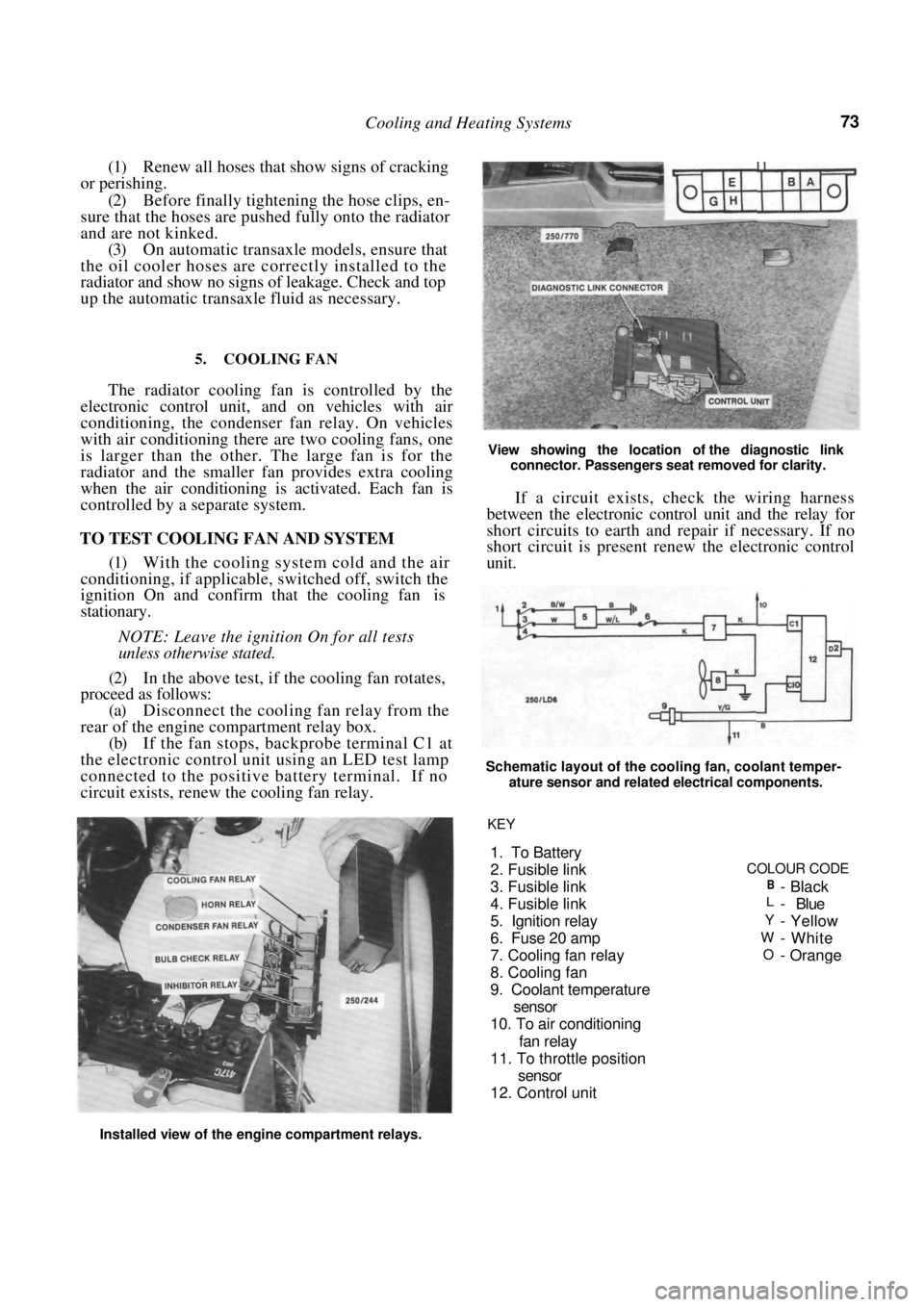
5. COOLING FAN
The radiator cooling fan is controlled by the
electronic control unit, and on vehicles with air
conditioning, the condenser fan relay. On vehicles
with air conditioning there are two cooling fans, one
is larger than the other. The large fan is for the
radiator and the smaller fan provides extra cooling
when the air conditioning is activated. Each fan is
controlled by a separate system.
TO TEST COOLING FAN AND SYSTEM
(1) With the cooling system cold and the air
conditioning, if applicable, switched off, switch the
ignition On and confirm that the cooling fan is
stationary.
NOTE: Leave the ignition On for all tests
unless otherwise stated.
(2) In the above test, if the cooling fan rotates,
proceed as follows:
(a) Disconnect the cooling fan relay from the
rear of the engine compartment relay box.
(b) If the fan stops, backprobe terminal C1 at
the electronic control unit using an LED test lamp
connected to the positive battery terminal. If no
circuit exists, renew the cooling fan relay.
View showing the location of the diagnostic link
connector. Passengers seat removed for clarity.
If a circuit exists, check the wiring harness
between the electronic control unit and the relay for
short circuits to earth and repair if necessary. If no
short circuit is present renew the electronic control
unit.
Schematic layout of the cooling fan, coolant temper-
ature sensor and related electrical components.
Installed view of the engine compartment relays. KEY
1. To Battery
2. Fusible link
COLOUR CODE
3. Fusible link
B-Black
4. Fusible linkL- Blue
5. I
gnition relayY- Yellow
6. Fuse 20 am
pW-White
7. Coolin
g fan relayO-Orange
8. Coolin
g fan
9. Coolant tem
perature
sensor
10. To air conditionin
g
fan rela
y
11. To throttle
position
sensor
12. Control unit
Page 216 of 238

216 Electrical System
NOTE: While checking the operation of the
fusible link, loosely connect the battery-
terminal only, to safeguard against damage
to the wiring harness.
(5) If the circuit is still inoperative or the fusible
link burns out again, refer the problem to an auto-
motive electrician.
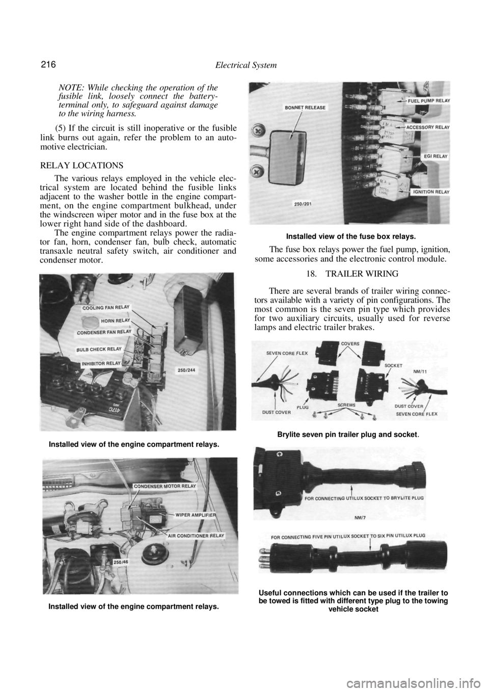
RELAY LOCATIONS
The various relays employed in the vehicle elec-
trical system are located behind the fusible links
adjacent to the washer bottle in the engine compart-
ment, on the engine compartment bulkhead, under
the windscreen wiper motor and in the fuse box at the
lower right hand side of the dashboard.
The engine compartment relays power the radia-
tor fan, horn, condenser fan, bulb check, automatic
transaxle neutral safety switch, air conditioner and
condenser motor.
Installed view of the fuse box relays.
The fuse box relays power the fuel pump, ignition,
some accessories and the el ectronic control module.
18. TRAILER WIRING
There are several brands of trailer wiring connec-
tors available with a variet y of pin configurations. The
most common is the seven pin type which provides
for two auxiliary circuits, usually used for reverse
lamps and electric trailer brakes.
Installed view of the engine compartment relays.
Installed view of the engine compartment relays.
Useful connections which can be used if the trailer to
be towed is fitted with different type plug to the towing
vehicle socket
Brylite seven pin trailer plug and socket.