fuse diagram NISSAN PULSAR 1987 Workshop Manual
[x] Cancel search | Manufacturer: NISSAN, Model Year: 1987, Model line: PULSAR, Model: NISSAN PULSAR 1987Pages: 238, PDF Size: 28.91 MB
Page 4 of 238

FRONT SUSPENSION............................ 156
Specifications......................................................... 156
Front suspension tr ouble shooting ........................ 156
Description ............................................................ 157
Steering knuckle.................................................... 157
Suspension unit..................................................... 159
Control arm ........................................................... 161
Stabiliser bar ........................................................ 162
Suspension and steering angles .......................... 163
REAR SUSPENSION................................ 164
Specifications ........................................................ 164
Rear suspension tr ouble shooting ........................ 164
Description ............................................................ 165
Rear hub ............................................................... 166
Suspension unit .................................................... 167
Control arm ........................................................... 169
Knuckle assembly.................................................. 170
Stabiliser bar ........................................................ 170
Rear wheel alignment ........................................... 171
BRAKES...................................................... 172
Specifications......................................................... 172
Brakes trouble shooting ........................................ 172
Description ............................................................ 174
Master cyli nder...................................................... 175
Brake servo unit .................................................... 177
Front brakes ......................................................... 178
Rear disc brakes................................................... 181
Rear drum brakes ................................................. 184
Handbrake cable and le ver assembly ................... 186
Brake adjustments ................................................ 187
Brake pedal ........................................................... 187
Hydraulic system................................................... 188
ELECTRICAL SYSTEM............................ 190
Specifications......................................................... 190
Battery and charging system trouble shooting ....... 190
Battery and starting system trouble shooting ........ 191
Lighting system trouble shooting ........................... 192
Turn signal lamp trouble shooting ........................ 192
Test equipment and so me applications................. 193
Battery ................................................................... 194
Alternator ............................................................... 196
Starter motor ......................................................... 201
Ignition system ...................................................... 206
Steering wheel ....................................................... 206
Switches and controls........................................... 206
Instrument cluster.................................................. 209
Blower fan .............................................................. 209
Radio/cassette...................................................... 209
lamp units ............................................................ 210
Windscreen wiper ................................................. 213
Fuses, fusible links and relays ............................. 215
Trailer wiring ......................................................... 216
Wiring diagrams ................................................... 218
BODY........................................................... 225
Windscreen and re ar glass .................................. 225
Front doors ........................................................... 225
Rear doors............................................................ 228
Engine bonnet...................................................... 231
Tailgate and lock — hatchback ............................ 231
Luggage compartment lid and lock — sedan ........ 233
Radiator grille.............................................................. 234
Centre console...................................................... 234 Dashboard ............................................................ 235
Scat belts ............................................................. 236
Seats .................................................................... 236
Vehicle cleaning ........................................................... 237
CONVERSION TABLES.......................... 238
Page 109 of 238
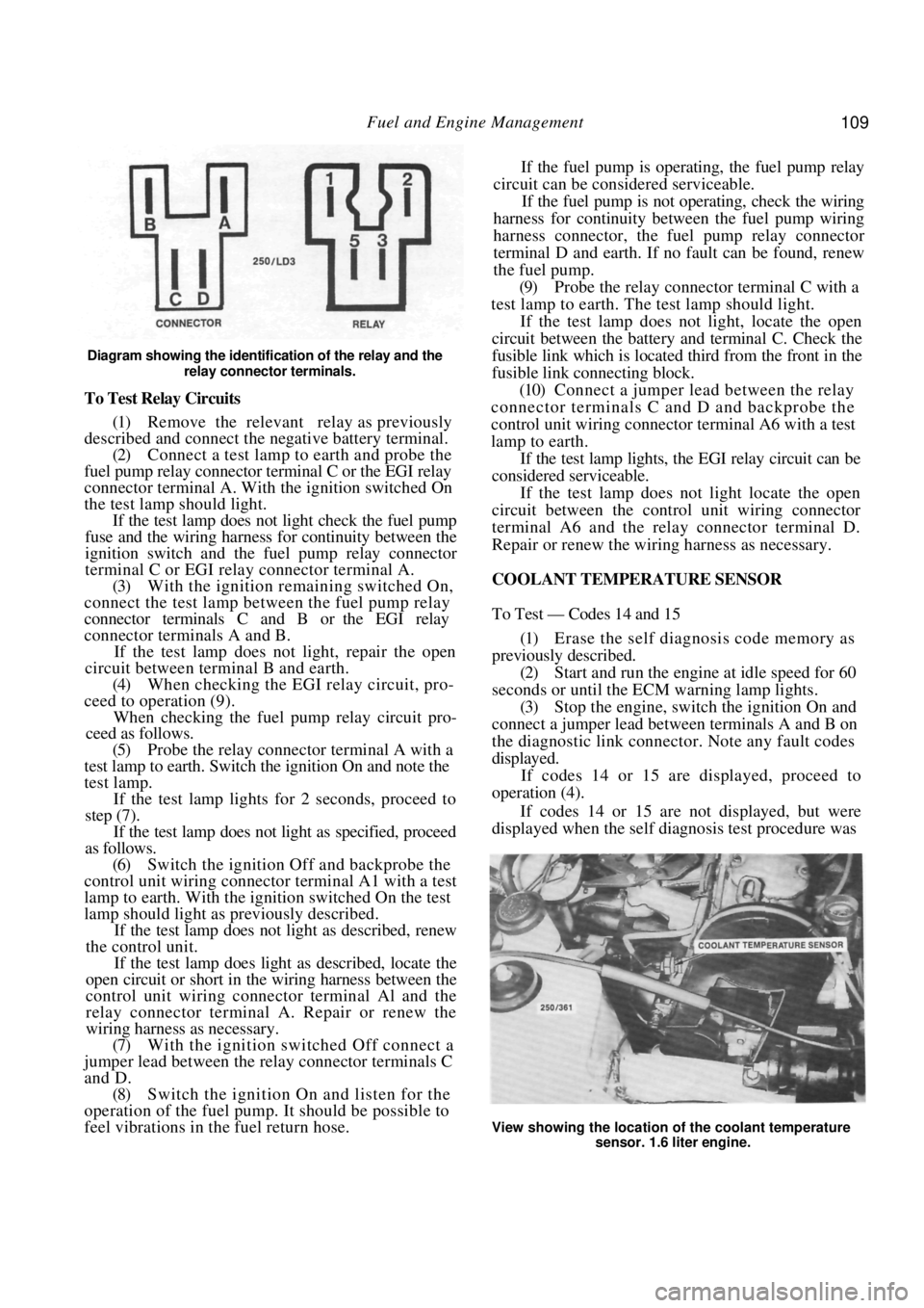
Fuel and Engine Management 109
Diagram showing the identification of the relay and the relay connector terminals.
To Test Relay Circuits
(1) Remove the relevant relay as previously
described and connect the ne gative battery terminal.
(2) Connect a test lamp to earth and probe the
fuel pump relay connector terminal C or the EGI relay
connector terminal A. With the ignition switched On
the test lamp should light. If the test lamp does not light check the fuel pump
fuse and the wiring harness for continuity between the
ignition switch and the fuel pump relay connector
terminal C or EGI rela y connector terminal A.
(3) With the ignition remaining switched On,
connect the test lamp between the fuel pump relay
connector terminals C and B or the EGI relay
connector terminals A and B.
If the test lamp does not light, repair the open
circuit between terminal B and earth.
(4) When checking the EGI relay circuit, pro-
ceed to operation (9).
When checking the fuel pu mp relay circuit pro-
ceed as follows.
(5) Probe the relay connector terminal A with a
test lamp to earth. Switch the ignition On and note the
test lamp.
If the test lamp lights for 2 seconds, proceed to
step (7).
If the test lamp does not light as specified, proceed
as follows.
(6) Switch the ignition Off and backprobe the
control unit wiring connector terminal A1 with a test
lamp to earth. With the ignition switched On the test
lamp should light as previously described.
If the test lamp does not light as described, renew
the control unit.
If the test lamp does light as described, locate the
open circuit or short in the wiring harness between the
control unit wiring connector terminal Al and the
relay connector terminal A. Repair or renew the
wiring harness as necessary.
(7) With the ignition switched Off connect a
jumper lead between the relay connector terminals C
and D. (8) Switch the ignition On and listen for the
operation of the fuel pump. It should be possible to
feel vibrations in the fuel return hose. If the fuel pump is operating, the fuel pump relay
circuit can be considered serviceable.
If the fuel pump is not operating, check the wiring
harness for continuity between the fuel pump wiring
harness connector, the fuel pump relay connector
terminal D and earth. If no fault can be found, renew
the fuel pump.
(9) Probe the relay connector terminal C with a
test lamp to earth. The test lamp should light.
If the test lamp does not light, locate the open
circuit between the battery and terminal C. Check the
fusible link which is located third from the front in the
fusible link connecting block.
(10) Connect a jumper lead between the relay
connector terminals C and D and backprobe the
control unit wiring connector terminal A6 with a test
lamp to earth.
If the test lamp lights, the EGI relay circuit can be
considered serviceable.
If the test lamp does not light locate the open
circuit between the contro l unit wiring connector
terminal A6 and the relay connector terminal D.
Repair or renew the wiring harness as necessary.
COOLANT TEMPERATURE SENSOR
To Test — Codes 14 and 15
(1) Erase the self diagnosis code memory as
previously described. (2) Start and run the engine at idle speed for 60
seconds or until the ECM warning lamp lights.
(3) Stop the engine, switch the ignition On and
connect a jumper lead between terminals A and B on
the diagnostic link connect or. Note any fault codes
displayed. If codes 14 or 15 are displayed, proceed to
operation (4).
If codes 14 or 15 are not displayed, but were
displayed when the self diagnosis test procedure was
View showing the location of the coolant temperature
sensor. 1.6 liter engine.
Page 219 of 238
Electrical System 219
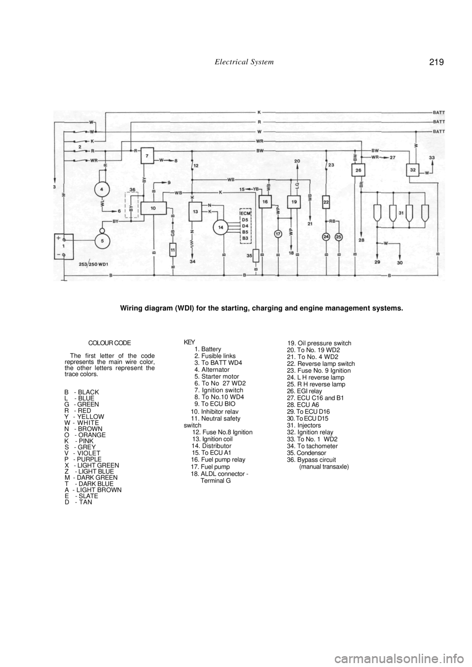
Wiring diagram (WDI) for the starting, charging and engine management systems.
COLOUR CODE
The first letter of the code
represents the main wire color,
the other letters represent the
trace colors.
B - BLACK
L - BLUE
G - GREEN
R - RED
Y - YELLOW
W - WHITE
N - BROWN
O - ORANGE
K - PINK
S - GREY V - VIOLET
P - PURPLE X - LIGHT GREEN
Z - LIGHT BLUE
M - DARK GREEN
T - DARK BLUE
A - LIGHT BROWN
E - SLATE
D - TAN
KEY 1. Battery
2. Fusible links
3. To BATT WD4
4. Alternator
5. Starter motor
6. To No 27 WD2
7. Ignition switch
8. To No.10 WD4
9. To ECU BIO
10. Inhibitor relav
11. Neutral safety
switch
12. Fuse No.8 Ignition
13. Ignition coil
14. Distributor
15. To ECU A1
16. Fuel pump relay
17. Fuel pump
18. ALDL connector - Terminal G
19. Oil pressure switch
20. To No. 19 WD2
21. To No. 4 WD2
22. Reverse lamp switch
23. Fuse No. 9 Ignition
24. L H reverse lamp
25. R H reverse lamp
26. EGI relay
27. ECU C16 and B1
28. ECU A6
29. To ECU D16
30. To ECU D15
31. Injectors
32. Ignition relay
33. To No. 1 WD2
34. To tachometer
35. Condensor
36. Bypass circuit (manual transaxle)
Page 220 of 238
220 Electrical System
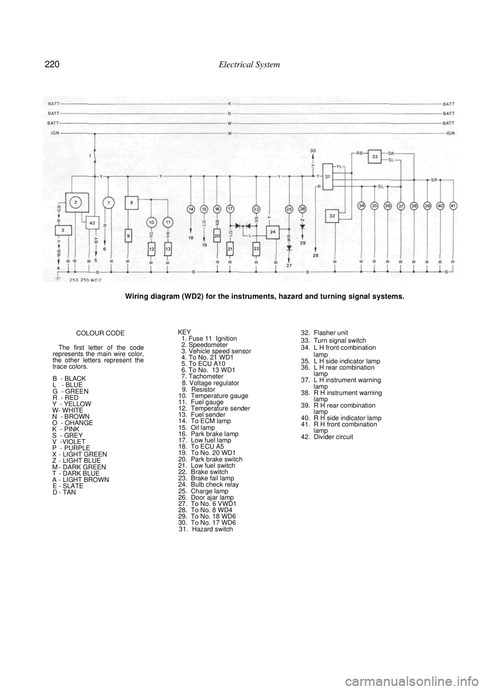
Wiring diagram (WD2) for the instruments, hazard and turning signal systems.
COLOUR CODE
The first letter of the code
represents the main wire color,
the other letters represent the
trace colors.
B - BLACK
L - BLUE
G - GREEN
R - RED
Y - YELLOW
W- WHITE
N - BROWN
O - OHANGE
K - PINK
S - GREY V -VIOLET
P - PURPLE X - LIGHT GREEN Z - LIGHT BLUE M - DARK GREEN T - DARK BLUE A - LIGHT BROWN E - SLATE D - TAN
KEY 1. Fuse 11 Ignition
2. Speedometer
3. Vehicle speed sensor
4. To No. 21 WD1
5. To ECU A10
6. To No. 13 WD1
7. Tachometer
8. Voltage regulator
9. Resistor
10. Temperature gauge
11. Fuel gauge
12. Temperature sender
13. Fuel sender
14. To ECM lamp
15. Oil lamp
16. Park brake lamp
17. Low fuel lamp
18. To ECU A5
19. To No. 20 WD1
20. Park brake switch
21. Low fuel switch
22. Brake switch
23. Brake fail lamp
24. Bulb check relay
25. Charge lamp
26. Door ajar lamp
27. To No. 6 VWD1
28. To No. 8 WD4
29. To No. 18 WD6
30. To No. 17 WD6 31. Hazard switch
32. Flasher unit
33. Turn signal switch
34. L H front combination
lamp
35. L H side indicator lamp
36. L H rear combination lamp
37. L H instrument warning
lamp
38. R H instrument warning lamp
39. R H rear combination lamp
40. R H side indicator lamp
41. R H front combination lamp
42. Divider circuit
Page 221 of 238
Electrical System 221
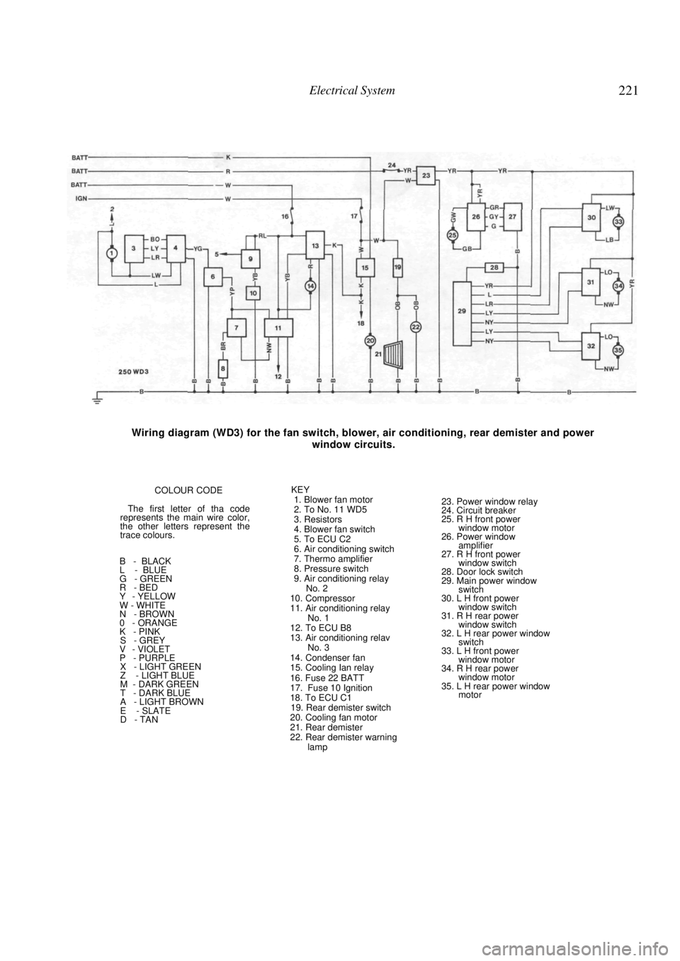
Wiring diagram (WD3) for the fan switch, blower, air conditioning, rear demister and power
window circuits.
COLOUR CODE
The first letter of tha code
represents the main wire color,
the other letters represent the
trace colours.
B - BLACK
L - BLUE
G - GREEN
R - BED
Y - YELLOW
W - WHITE
N - BROWN
0 - ORANGE
K - PINK
S - GREY
V - VIOLET
P - PURPLE
X - LIGHT GREEN
Z - LIGHT BLUE
M - DARK GREEN
T - DARK BLUE
A - LIGHT BROWN
E - SLATE
D - TAN KEY
1. Blower fan motor
2. To No. 11 WD5
3. Resistors
4. Blower fan switch
5. To ECU C2
6. Air conditioning switch
7. Thermo amplifier
8. Pressure switch
9. Air conditioning relay No. 2
10. Compressor
11. Air conditioning relay No. 1
12. To ECU B8
13. Air conditioning relav No. 3
14. Condenser fan
15. Cooling Ian relay
16. Fuse 22 BATT
17. Fuse 10 Ignition
18. To ECU C1
19. Rear demister switch
20. Cooling fan motor
21. Rear demister
22. Rear demister warning lamp
23. Power window relay
24. Circuit breaker
25. R H front power
window motor
26. Power window amplifier
27. R H front power window switch
28. Door lock switch
29. Main power window switch
30. L H front power
window switch
31. R H rear power window switch
32. L H rear power window switch
33. L H front power
window motor
34. R H rear power window motor
35. L H rear power window motor
Page 222 of 238

222 Electrical System
Wiring diagram (WD4) for the horn, audio, front wiper/washer and rear wiper/washer circuits.
COLOUR CODE
The first letter of the code
represents the main wire color.
the other letters represent the
trace colors.
B - BLACK
L - BLUE
G - GREEN
R - RED
Y - YELLOW
W - WHITE
N - BROWN
O - ORANGE
K - PINK
S - GREY V - VIOLET
P - PURPLE X - LIGHT GREEN
Z - LIGHT BLUE
M - DARK GREEN
T - DARK BLUE
A - LIGHT BROWN
E - SLATE
D - TAN
KEY 1. Fuse No. 18 Batt
2. Horn relay
3. Horn switch
4. Horn
5. Stop lamp switch
6. L H stop lamp
7. R H stop lamp
8. To No. 28 WD2
9. To No. 14 WD6
10. To No. 8 WD1
11. Radio cassette and clock
12. L H front speaker
13. L H rear speaker
14. R H front speaker
15. R H rear speaker
16. Fuse No. 19 Batt
17. Fuse No. 20 Batt
18. Fuse No. 6 ACC
19. Rear washer motor
20. Rear wiper/washer
motor
21. Rear wiper motor
22. Fuse No. 7 ACC
23. Front wiper motor
24. Front washer motor
25. Intermittent wiper relay
26. Front wiper/washer
switch
27. Variable intermittent
switch
Page 223 of 238

Electrical System 223
Wiring diagram (WD5) for the mirrors, cigarette lighter and door lock circuits.
COLOUR CODE
The first letter of the code
represents the main wire color,
the other letters represent the
trace colors.
B - BLACK
L - BLUE
G - GREEN
R - RED
Y - YELLOW
W - WHITE
N - BROWN
O - ORANGE
K - PINK
S - GREY V - VIOLET
P - PURPLE X - LIGHT GREEN
Z - LIGHT BLUE
M - DARK GREEN
T - DARK BLUE
A - LIGHT BROWN
E - SLATE
D - TAN
KEY 1. Accessories relay
2. R H power mirror 3. L H power mirror
4. Power mirror switch
5. Fuse No. 3 ACC
6. Fuse No. 4 ACC
7. Fuse No. 5 ACC
8. Fuse No 21 B
9. Cigarette lighter
10. To No. 13 WD6
11. To No. 2 WD3
12. Door lock timer
13. Front door lock switch
14. Key lock switch
15. Door lock switch
16. L H front door lock solenoid
17. R H rear door lock solenoid
18. L H rear door lock
solenoid
Page 224 of 238
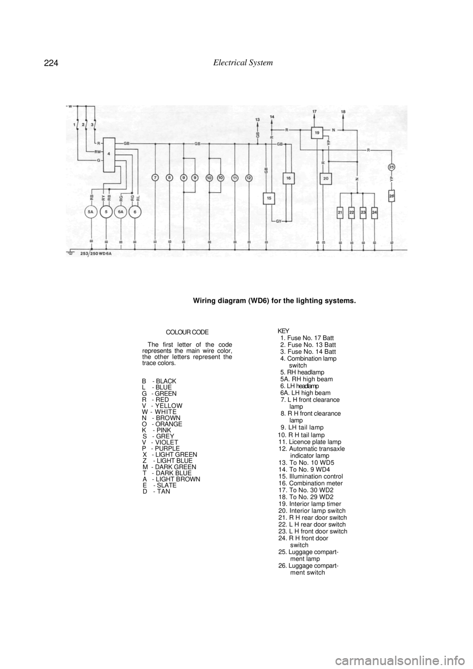
224 Electrical System
Wiring diagram (WD6) for the lighting systems.
COLOUR CODE
The first letter of the code
represents the main wire color,
the other letters represent the
trace colors.
B - BLACK
L - BLUE
G - GREEN
R - RED
V - YELLOW
W - WHITE
N - BROWN
O - ORANGE
K - PINK
S - GREY V - VIOLET
P - PURPLE X - LIGHT GREEN
Z - LIGHT BLUE
M - DARK GREEN
T - DARK BLUE
A - LIGHT BROWN
E - SLATE
D - TAN
KEY 1. Fuse No. 17 Batt
2. Fuse No. 13 Batt
3. Fuse No. 14 Batt
4. Combination lamp
switch
5. RH headlamp
5A. RH high beam
6 . L H headlamp
6A. LH high beam 7. L H front clearance lamp
8. R H front clearance lamp
9. LH tail lamp
10. R H tail lamp 11. Licence plate lamp
12. Automatic transaxle indicator lamp
13. To No. 10 WD5
14. To No. 9 WD4
15. Illumination control
16. Combination meter
17. To No. 30 WD2
18. To No. 29 WD2
19. Interior lamp timer
20. Interior lamp switch
21. R H rear door switch
22. L H rear door switch
23. L H front door switch
24. R H front door switch
25. Luggage compart- ment lamp
26. Luggage compart- ment switch