service indicator NISSAN PULSAR 1987 Workshop Manual
[x] Cancel search | Manufacturer: NISSAN, Model Year: 1987, Model line: PULSAR, Model: NISSAN PULSAR 1987Pages: 238, PDF Size: 28.91 MB
Page 191 of 238

Electrical System 191
This is usually accompanied by discoloura-
tion of the electrolyte.
CHARGE INDICATOR LAMP REMAINS ON
• Loose or broken alternator drive belt: Adjust
or renew the drive belt.
• Faulty regulator unit: Check and renew the
regulator unit. • Faulty alternator: Check and overhaul the
alternator. • Short to earth in the warning lamp circuit:
Check and repair the circuit.
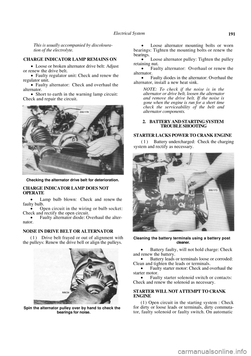
Checking the alternator drive belt for deterioration.
CHARGE INDICATOR LAMP DOES NOT
OPERATE
• Lamp bulb blown: Check and renew the
faulty bulb. • Open circuit in the wi ring or bulb socket:
Check and rectify the open circuit. • Faulty alternator diode: Overhaul the alter-
nator.
NOISE IN DRIVE BELT OR ALTERNATOR
(1) Drive belt frayed or out of alignment with
the pulleys: Renew the drive bell or align the pulleys.
• Loose alternator moun ting bolts or worn
bearings: Tighten the mounting bolts or renew the
bearings. • Loose alternator pulley: Tighten the pulley
retaining nut.
• Faulty alternator: Overhaul or renew the
alternator. • Faulty diodes in the alternator: Overhaul the
alternator, install a new heat sink.
NOTE: To check if the noise is in the
alternator or drive belt, loosen the alternator
and remove the drive belt. If the noise is
gone when the engine is run for a short time
check the serviceability of the belt and
alternator components.
2. BATTERY AND STARTING SYSTEM TROUBLE SHOOTING
STARTER LACKS POWER TO CRANK ENGINE
(1) Battery undercharged: Check the charging
system and rectify as necessary.
Cleaning the battery terminals using a battery post
cleaner.
• Battery faulty, will not hold charge: Check
and renew the battery. • Battery leads or terminals loose or corroded:
Clean and tighten the leads or terminals.
• Faulty starter motor: Check and overhaul the
starter motor. • Faulty starter solenoid switch or contacts:
Check and renew the solenoid as necessary.
STARTER WILL NOT ATTEMPT TO CRANK
ENGINE
(1 ) Open circuit in the starting system : Check
for dirty or loose leads or terminals, dirty commuta-
tor, faulty solenoid or faulty switch. On automatic
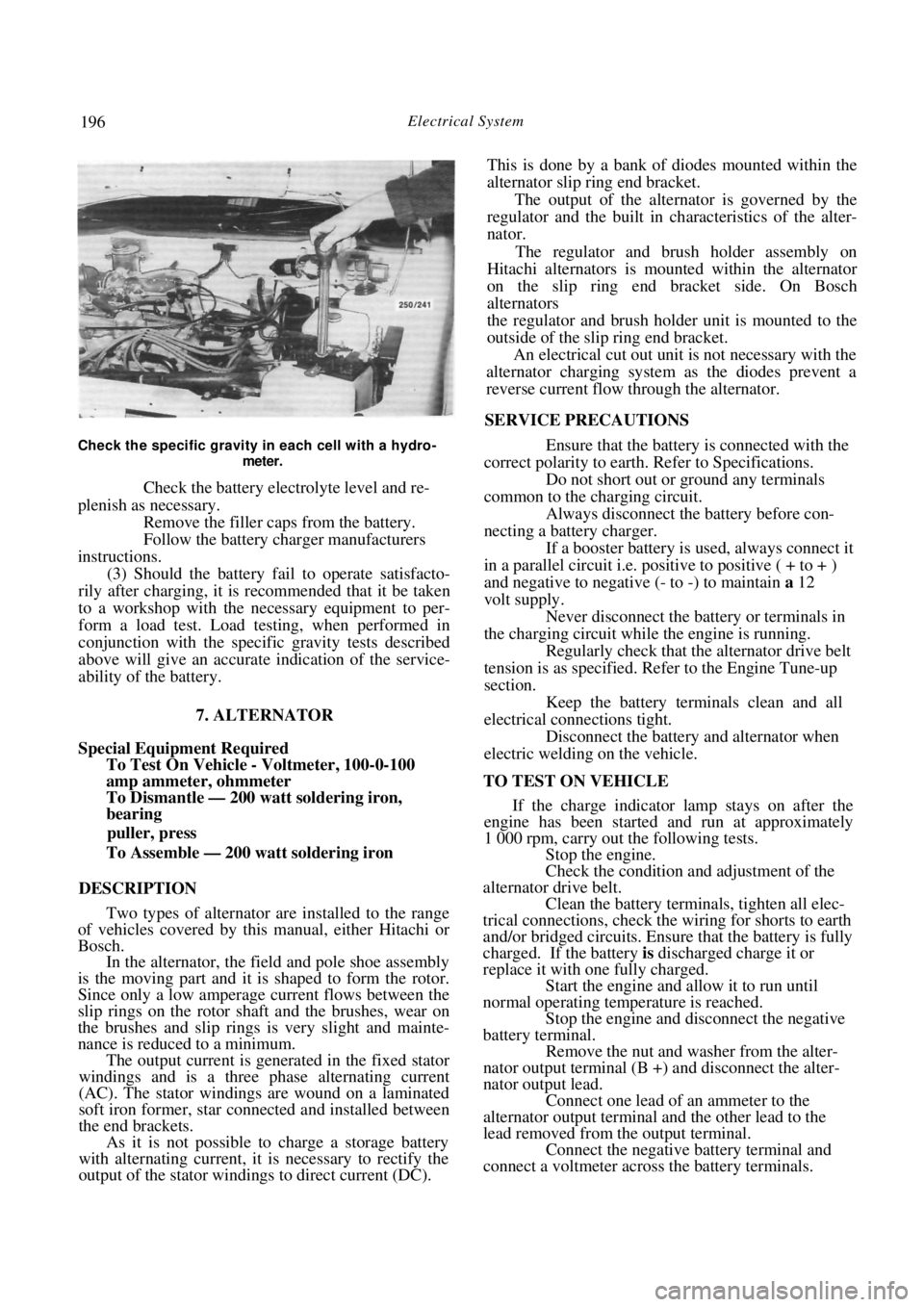
Spin the alternator pulley over by hand to check the
bearings for noise.
Page 196 of 238

196 Electrical System
Check the specific gravity in each cell with a hydro-
meter.
Check the battery electrolyte level and re-
plenish as necessary. Remove the filler cap s from the battery.
Follow the battery charger manufacturers
instructions. (3) Should the battery fail to operate satisfacto-
rily after charging, it is recommended that it be taken
to a workshop with the necessary equipment to per-
form a load test. Load testing, when performed in
conjunction with the specific gravity tests described
above will give an accurate indication of the service-
ability of the battery.
7. ALTERNATOR
Special Equipment Required
To Test On Vehicle - Voltmeter, 100-0-100
amp ammeter, ohmmeter
To Dismantle — 200 watt soldering iron,
bearing
puller, press
To Assemble — 200 watt soldering iron
DESCRIPTION
Two types of alternator are installed to the range
of vehicles covered by this manual, either Hitachi or
Bosch. In the alternator, the field and pole shoe assembly
is the moving part and it is shaped to form the rotor.
Since only a low amperage current flows between the
slip rings on the rotor shaft and the brushes, wear on
the brushes and slip rings is very slight and mainte-
nance is reduced to a minimum. The output current is generated in the fixed stator
windings and is a three phase alternating current
(AC). The stator windings are wound on a laminated
soft iron former, star connected and installed between
the end brackets. As it is not possible to charge a storage battery
with alternating current, it is necessary to rectify the
output of the stator windings to direct current (DC). This is done by a bank of diodes mounted within the
alternator slip ring end bracket.
The output of the alternator is governed by the
regulator and the built in ch aracteristics of the alter-
nator.
The regulator and brush holder assembly on
Hitachi alternators is mounted within the alternator
on the slip ring end bracket side. On Bosch
alternators
the regulator and brush holder unit is mounted to the
outside of the slip ring end bracket. An electrical cut out unit is not necessary with the
alternator charging system as the diodes prevent a
reverse current flow through the alternator.
SERVICE PRECAUTIONS
Ensure that the battery is connected with the
correct polarity to earth. Refer to Specifications.
Do not short out or ground any terminals
common to the charging circuit. Always disconnect the battery before con-
necting a battery charger.
If a booster battery is used, always connect it
in a parallel circuit i.e. positive to positive ( + to + )
and negative to negative (- to -) to maintain a 12
volt supply. Never disconnect the battery or terminals in
the charging circuit while the engine is running. Regularly check that the alternator drive belt
tension is as specified. Refer to the Engine Tune-up
section.
Keep the battery terminals clean and all
electrical connections tight. Disconnect the battery and alternator when
electric welding on the vehicle.
TO TEST ON VEHICLE If the charge indicator lamp stays on after the
engine has been started and run at approximately
1 000 rpm, carry out the following tests. Stop the engine.
Check the condition and adjustment of the
alternator drive belt. Clean the battery terminals, tighten all elec-
trical connections, check the wiring for shorts to earth
and/or bridged circuits. Ensure that the battery is fully
charged. If the battery is discharged charge it or
replace it with one fully charged. Start the engine and allow it to run until
normal operating temperature is reached.
Stop the engine and disconnect the negative
battery terminal.
Remove the nut and washer from the alter-
nator output terminal (B +) and disconnect the alter-
nator output lead. Connect one lead of an ammeter to the
alternator output terminal and the other lead to the
lead removed from the output terminal. Connect the negative battery terminal and
connect a voltmeter across the battery terminals.