service NISSAN QASHQAI 2006 User Guide
[x] Cancel search | Manufacturer: NISSAN, Model Year: 2006, Model line: QASHQAI, Model: NISSAN QASHQAI 2006Pages: 297, PDF Size: 4.09 MB
Page 128 of 297
Downloaded from www.Manualslib.com manuals search engine After parking in the sun, drive for two or three
minutes with the windows open to vent hot air
from the passenger compartment. Then, close
the windows. This will allow the acceleration of
the air conditioner’s cooling operation.
Keep windows closed while the air conditioner is
operating.
The air conditioning system should be operated
for about 10 minutes, at least once a month. This
helps prevent damage to the system due to lack
of lubrication.
If the coolant temperature gauge exceeds the
“HOT” position, turn the air conditioner off. For
additional information, see “Engine overheat” in
the “6. In case of emergency” section.
If the engine coolant reaches an extremely high
temperature, the air conditioning system will au-
tomatically turn off. This may happen for example
if the engine runs at idle speed for a long time on
a hot day.
Air conditioner filter
The air conditioning system is equipped with a filter
which collects dirt, pollen, dust, etc. To make sure
the air conditioner heats, defogs, and ventilates effi-
ciently, replace the filter regularly. To replace the fil-
ter, contact a NISSAN dealer or qualified workshop.
The filter should be replaced if the airflow is ex-
tremely reduced or when the windows fog up
easily while operating the heater or air condition-
ing system.
Servicing air conditioner
The air conditioning system in your NISSAN vehicle
is charged with an environmentally friendly refriger-
ant.
NISSAN GREEN PROGRAM
This refrigerant will not harm the earth’s ozone
layer.
Special charging equipment and lubricant are re-
quired when servicing the NISSAN air conditioner.
Using improper refrigerants or lubricants will cause
severe damage to the air conditioning system. See
“Air conditioning system refrigerant and lubricant
recommendations (where fitted)” in the “9. Techni-
cal information” section.
A NISSAN dealer or qualified workshop will be able
to service the air conditioning system.
WARNING
Do not adjust the audio system while driving.
The audio system operates when the ignition switch
is in the Acc or ON position. If you want to listen to
the radio or CD while the engine is not running, turn
the ignition switch to the Acc position. Do not use
for an extended period of time with the engine
stopped.
AUDIO OPERATION PRECAUTIONS
NOTE
Models with NISSAN Connect system, see the
audio operation precautions in the separately
provided NISSAN Connect Owner’s Manual.
Radio
Radio reception is affected by station signal
strength, distance from radio transmitter, build-
ings, bridges, mountains and other external influ-
ences. Intermittent changes in reception quality
are normally caused by these external influences.
Using a mobile phone in or near the vehicle may
influence radio reception quality.
Use the antenna for the best reception.
Compact Disc (CD) player
During cold weather or rainy days, the player
may malfunction due to the humidity. If this
occurs, remove the CD and dehumidify or
ventilate the player completely.
AUDIO SYSTEM
Display screen, heater and air conditioner, and audio system4-21
Page 132 of 297
Downloaded from www.Manualslib.com manuals search engine Band select button
Press the button to change the reception
wave band as follows:
FM1 →FM 2 →FM T →MW →LW →FM1
When button is pressed while the igni-
tion switch is in the Acc or ON position, the radio
will come on at the last received radio station. If the
CD is already playing, pressing the but-
ton will switch off the CD play mode and the last
received radio station will be selected.
FM Auto store
When the button is pressed for more
than 1.5 seconds and the six strongest stations are
stored in the preset (1 to 6) of the FM T band. Dur-
ing the search, a notification message [AU-
TOSTORE] appears in the display and the sound is
muted until the operation is complete. Once com-
pleted, the radio selects preset 1.
Manual tuning buttons
WARNING
The radio should not be tuned while driving in
order for full attention to be given to the driving
operation.
Press the
orbutton repeatedly to in-
crease or decrease the frequency. The frequency increases or decreases in steps of
100 kHz on the FM band, 9kHz on the MW band,
and 3 kHz on the LW band.
If the
orbutton is held down with a long
press, the frequency will continuously increase or
decrease until the button is released.
SEEK tuning buttons
Pressing briefly on theorbutton starts the
tuning mode. The radio tuner seeks from low to high
or high to low frequencies and stops at the next
broadcasting station. During seek mode, the audio
output is muted. If no broadcasting station can be
found within the complete band cycle, it will return
to the initial frequency.
If the
orbutton is held down with a long
press, the seek mode will continuously increase or
decrease until the button is released. When the but-
ton is released, the seek mode will seek the next
broadcasting station.
Preset station buttonsj1j2j3j4j5j6
Pressing a preset button for less than 2 seconds will
select the stored radio station.
Pressing a preset button for more than 2 seconds
will cause the station currently being received to be
stored against that preset button.
Eighteen stations can be stored in the FM band.
(Six each for FM1, FM2 and FMT)
Six stations can be set for both the MW and LW
bands. If the battery is disconnected, or if the fuse blows,
the radio memory will be erased. In that case, reset
the desired stations after battery connection or fuse
replacement.
Radio data system (RDS) operation
The RDS is a system through which encoded digital
information is transmitted by FM radio station in ad-
dition to the normal FM-radio broadcasting. The
RDS provides information services such as station
name, traffic information and news.
NOTE
In some countries or regions, some of these ser-
vices may not be available.
Alternative Frequency (AF) mode:
The AF mode operates in the FM (radio) mode.
The AF mode operates both in the FM (radio)
and CD mode (if FM was previously selected in
the radio mode).
When AF mode has been set to the “ON” posi-
tion in the user set up menu mode, the [AF] indi-
cator comes on. For activation or deactivation
details, see “MENU button” later in this section.
The AF function compares signal strengths and se-
lects the station with the optimum reception condi-
tions for the currently tuned-in station.
Display screen, heater and air conditioner, and audio system4-25
Page 133 of 297
Downloaded from www.Manualslib.com manuals search engine RDS functions
Programme Service (PS) function (station name
display function):
When an RDS station is tuned in with seek or manual
tuning, the RDS data is received and the PS name
is displayed.
Emergency broadcast interrupt function
(ALARM INTERRUPTION - EBU SPEC FOR
INFO):
When the radio receives PTY code 31 (an emer-
gency broadcast code), the sound is interrupted,
the emergency broadcast is heard, and [ALARM] is
displayed. The volume level at this time is the same
as that for traffic announcements. Once the emer-
gency broadcast is finished, the unit immediately
returns to the previous source.
REG (Regional) mode:
Some local radio stations are linked according to
region because they only offer limited coverage due
a limited number of transmitters. If the signal from
one station of these stations becomes weak while
driving, RDS mode will switch to another local sta-
tion in the region with a stronger signal.
When the REG mode is activated in the FM band
and the radio receiver is tuned to a local radio sta-
tion, it will keep receiving this radio station without
switching to another local station. For activation or
deactivation details, see “MENU button” later in this
section.
TA Traffic announcement
This function operates in both FM (radio) and CD
mode.
Pressing the
mode. The TA indicator is displayed while TA
mode is on.
When the
The mode will be switched off and the TA indica-
tor will disappear from the display.
If the TA mode is not activated ,aTiconwill
appear in the display when the currently received
radio station is capable of broadcasting traffic
announcements. Pressing the
ton will activate TA mode and the indicator will
change from T to TA.
Traffic announcement interrupt function:
When a traffic announcement is received, the an-
nouncement is tuned in.
Once the traffic announcement has finished, the unit
returns to the source that was active before the traf-
fic announcement started. The volume returns to the
previous level.
If the
announcement, the traffic announcement interrupt
mode is cancelled. The TA mode returns to the
standby mode and the audio unit returns to the pre-
vious source. NOTE
TA mode operates regardless of whether the AF
mode is on or off.
NEWS mode
When the NEWS mode is activated and the radio
receives a NEWS code from a FM broadcasting
station, the playing mode will be interrupted. Once
the news broadcast has finished, the audio unit will
return to the previous source. During the interrup-
tion, NEWS and the broadcasting station name will
be displayed.
To enable or disable the NEWS mode, press the
button for more than 2 seconds. When
the NEWS mode is enabled, the NEWS icon will be
displayed.
1. NEWS standby mode
The NEWS standby mode can be activated while
in FM or CD mode.
Pressing the TA NEWS button for more than 2
seconds, the NEWS standby mode will switch
off and the NEWS icon will disappear from the
display.
2. NEWS interruption mode
Pressing the
2 seconds, the NEWS standby mode will switch
off and the NEWS icon will disappear from the
display.
4-26Display screen, heater and air conditioner, and audio system
Page 140 of 297
Downloaded from www.Manualslib.com manuals search engine Eighteen stations can be stored in the FM band.
(Six each for FM1, FM2 and FMT)
Six stations can be set for the AM band.
If the battery is disconnected, or if the fuse blows,
the radio memory will be erased. In that case, reset
the desired stations after battery connection or fuse
replacement.
Radio data system (RDS) operation
The RDS is a system through which encoded digital
information is transmitted by FM radio stations in
addition to the normal FM radio broadcasting. The
RDS provides information services such as station
name, traffic information, or news.
NOTE
In some countries or regions, some of these ser-
vices may not be available.
Alternative Frequency (AF) mode:
The AF mode operates in the FM (radio) mode.
The AF mode operates in the FM (radio), AUX or
CD mode (if FM was previously selected in the
radio mode).
The AF function compares signal strengths and
selects the station with the optimum reception
conditions for the currently tuned-in station.
RDS functions
Programme Service (PS) function (station name
display function):
When an RDS station is tuned in with seek or manual
tuning, the RDS data is received and the PS name
is displayed.
TA Traffic announcement
This function operates in FM (Radio), CD or AUX
mode.
Pressing the
The TA indicator is displayed while TA mode is
on.
When
switched off and the TA indicator will disappear
from the display.
Traffic announcement interrupt function:
When a traffic announcement is received, the an-
nouncement is tuned in and the display shows a
notification message with the radio station name e.g.
[TA: Radio 1].
Once the traffic announcement has finished, the unit
returns to the source that was active before the traf-
fic announcement started.
If
the traffic announcement interrupt mode is can-
celled. The TA mode returns to the standby mode
and the audio unit returns to the previous source.
SETUP BUTTON
To configure Audio, Clock, Bluetooth, Language or
Scroll direction settings, perform the following pro-
cedure:
1. Press the
2. Turn the
clockwise, the display will appear in the following
order:
[Audio] ⇔[Clock] ⇔[Bluetooth] ⇔[Language]
⇔ [Scroll Direction]
After the desired levels have been set, press either
the
(Back) button repeatedly, the
button, or wait for 8 seconds without pressing any
buttons to exit the menu screen.
Display brightness (Day/Night mode)
Press the
switch the display brightness between the daytime
and nighttime mode.
Audio adjustments
Press the
screen then select [Audio].
Each time the
will change as follows:
[Bass] →[Treble] →[Balance] →[Fade] →[AUX
VOL] →[SPD VOL] →setup menu screen [Audio]
→ [Bass]
Display screen, heater and air conditioner, and audio system4-33
Page 151 of 297
Downloaded from www.Manualslib.com manuals search engine in this section or “Mobile phone integration for FM
AM radio with CD player” later in this section.
SOURCE button
Repeatedly press the SOURCE button to select a
source.
mVolume control buttons
Press the + or — button to adjust the volume.When installing large capacity wireless equipment
or a car phone in your NISSAN, be sure to observe
the following as it may adversely affect the Engine
control system and other electronic parts depend-
ing on its installation location.
CAUTION
Keep the antenna as far as possible away from
the Electric Control Module.
Also keep the antenna wire more than 20 cm
(8 inches) away from the Electro Injection har-
ness. Do not route the antenna wire next to
any harness.
Adjust the antenna standing-wave ratio as rec-
ommended by the manufacturer.
Connect the ground wire from the radio chas-
sis to the body.
NOTE
For further information, visit the NISSAN web site:
www.nissan-europe.com. Select your country
from the list and go to the “SERVICES” menu. If
not available on the web site, contact a NISSAN
dealer or qualified workshop.
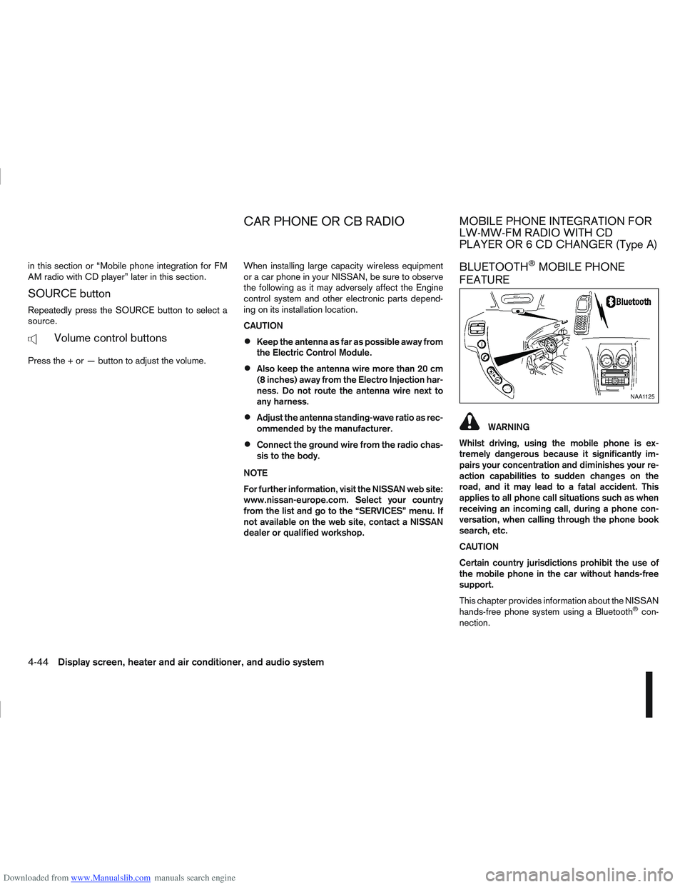
BLUETOOTH®MOBILE PHONE
FEATURE
WARNING
Whilst driving, using the mobile phone is ex-
tremely dangerous because it significantly im-
pairs your concentration and diminishes your re-
action capabilities to sudden changes on the
road, and it may lead to a fatal accident. This
applies to all phone call situations such as when
receiving an incoming call, during a phone con-
versation, when calling through the phone book
search, etc.
CAUTION
Certain country jurisdictions prohibit the use of
the mobile phone in the car without hands-free
support.
This chapter provides information about the NISSAN
hands-free phone system using a Bluetooth
®con-
nection.
NAA1125
CAR PHONE OR CB RADIOMOBILE PHONE INTEGRATION FOR
LW-MW-FM RADIO WITH CD
PLAYER OR 6 CD CHANGER (Type A)
4-44Display screen, heater and air conditioner, and audio system
Page 166 of 297
Downloaded from www.Manualslib.com manuals search engine WARNING
Do not leave children or adults who would
normally require the support of others alone
in your vehicle. Pets should also not be left
alone. They could accidentally injure them-
selves or others through inadvertent opera-
tion of the vehicle. Also, on hot, sunny days,
temperatures in a closed vehicle could quickly
become high enough to cause severe or pos-
sibly fatal injuries to people or animals.
To prevent luggage or packages from sliding
forward during braking, do not stack anything
in the cargo area higher than the seatbacks.
Secure all cargo with ropes or straps to pre-
vent it from sliding or shifting.
Failure to follow proper seating instructions
see “Seats” in the “1. Safety — seats, seat
belts and supplemental restraint system” sec-
tion, could result in serious personal injury in
an accident or sudden stop.
EXHAUST GAS (Carbon Monoxide)
WARNING
Do not breathe exhaust gases; they contain
colourless and odourless carbon monoxide.
Carbon monoxide is a dangerous gas and can
cause unconsciousness or death.
If you suspect that exhaust fumes are enter-
ing the vehicle, drive with all windows fully
open and have the vehicle inspected immedi-
ately.
Do not run the engine in closed spaces, such
as a garage, for any longer than is absolutely
necessary.
Do not park the vehicle with the engine run-
ning for any extended length of time.
Keep the back door closed while driving, oth-
erwise exhaust gases could be drawn into the
passenger compartment. If you must drive in
this way for some reason, take the following
steps:
1) Open all the windows.
2) Set the air recirculation mode (
)tothe
“OFF” position.
3) Set the fan speed control to the maximum position to circulate the air.
If electrical wiring or other cable connections
must pass to a trailer through the seal of the
body, follow the manufacturer’s recommen-
dations to prevent carbon monoxide entry into
the vehicle.
When a vehicle has been stopped in an open
area with its engine running for any significant
length of time, turn the fan on to force outside
air into the vehicle.
The exhaust system and body should be in-
spected by a NISSAN dealer or qualified work-
shop whenever:
– the vehicle is raised for service.
– you suspect that exhaust fumes are enter-ing into the passenger compartment.
– you notice a change in the sound of the exhaust system.
– you have had an accident involving dam- age to the exhaust system, underbody, or
rear of the vehicle.
PRECAUTIONS WHEN STARTING
AND DRIVING
Starting and driving5-3
Page 168 of 297
Downloaded from www.Manualslib.com manuals search engine The turbocharger system uses engine oil for lubrica-
tion and cooling of its rotating components. The tur-
bocharger turbine turns at extremely high speeds
and it can reach an extremely high temperature. It is
essential to maintain a flow of clean oil through the
turbocharger system. A sudden interruption to the
oil supply may cause a malfunction in the turbo-
charger.
To ensure prolonged life and performance of the
turbocharger, it is essential to comply with the fol-
lowing maintenance procedure:
CAUTION
Change the engine oil of the turbo-charged
diesel engine as prescribed. See the sepa-
rately provided Warranty Information & Main-
tenance Booklet for additional information.
Use only the recommended engine oil. See
“Capacities and recommended
fuel/lubricants” in the “9. Technical
information” section.
If the engine has been operating at high rpm
for an extended period of time, let it idle for a
few minutes prior to shutdown.
Do not accelerate the engine to high rpm im-
mediately after starting it.
WARNING
Be careful not to burn yourself with exhaust
gases.
Do not park the vehicle over flammable mate-
rials such as dry grass, waste paper or rags,
as they may burn easily.
If the vehicle continues to be driven at a low
speed with the DPF warning light illuminated,
the fail-safe will limit engine revolutions and/
or torque. In this case, the engine oil must be
replaced and the process of burning accumu-
lated particulate matter must be carried out
by a NISSAN dealer or qualified workshop.
Service regeneration is a maintenance item
and is not covered by the NISSAN warranty.
Use engine oil for DPF equipped models. For
details, see “Capacities and recommended
fuel/lubricants” in the “9. Technical
information” section.
CAUTION
The DPF becomes extremely hot after burning
particulate matter.
NISSAN GREEN PROGRAM
Some diesel engine models are fitted with a Diesel
Particulate Filter (DPF), which is a device that re-
moves carbon (soot) from the exhaust gas. To oper-
ate effectively, the DPF system must routinely con-
duct a cleaning operation, called regeneration, that burns-off the accumulated carbon. This regenera-
tion process is normally automatic and not visible to
the driver.
REGENERATION RESTRICTIONS
Driving conditions such as frequent short journeys
or stop/start driving can result in excessive build up
of carbon in the filter. When this happens the DPF
warning light
will illuminate (and a message
will appear in the vehicle information display, see
“Vehicle information display” later in this section) to
inform you that the vehicle must be driven in a par-
ticular manner to begin regeneration.
When the DPF warning light is illuminated, provided
that legal and safety conditions allow, the vehicle
should be driven at a speed of over 60 km/h (37.5
MPH) until the DPF warning light turns off. This pro-
cess can take up to 30 minutes to complete.
IF REGENERATION FAILS
Failure to react to the DPF warning lightmay
lead to saturation of the DPF system. If this hap-
pens, the Malfunction Indicator (MI)
will also
illuminate to indicate that a Service Regeneration by
a NISSAN dealer or qualified workshop is required.
The engine speed may also be limited to 3,000 rpm
to protect the DPF system.
NOTE
Contact a NISSAN dealer or qualified workshop
to perform a forced regeneration.
TURBOCHARGER SYSTEM
(Diesel engine models) DIESEL PARTICULATE FILTER
(DPF) (where fitted)
Starting and driving5-5
Page 199 of 297
Downloaded from www.Manualslib.com manuals search engine steep slope consider the incline (the towing
weights quoted are for a 12% slope).
Follow the trailer manufacturer’s instructions.
Have your vehicle serviced more often than at
the intervals specified in the separately provided
Warranty Information and Maintenance booklet.
Trailer towing requires more fuel than under nor-
mal circumstances because of a considerable
increase in traction power required and resis-
tance.
When towing a trailer, observe the following re-
stricted towing speed:
Speed: below 100 km/h (62 MPH)
CAUTION
While towing a trailer, check the engine coolant
temperature gauge regularly to prevent engine
overheating.
TYRE PRESSURE
When towing a trailer, inflate the vehicle tyres to the
maximum recommended COLD tyre pressure, as
indicated on the tyre placard (for full loading). Make
sure the trailer tyre pressures are correct.
CAUTION
Do not tow a trailer when the vehicle is installed
with a temporary-use spare tyre.
SAFETY CHAINS
Always use a suitable chain between the vehicle
and trailer. The chain should be attached to the hitch
and not to the vehicle bumper or axle. Be sure to
leave enough slack in the chain to permit turning
corners. The chain should not drag on the ground:
passing the chain across the trailer hitch may be the
best practice depending on your trailer.
TRAILER BRAKES
Ensure that trailer brakes are installed as required
by local regulations. Also check that all other trailer
equipment conforms to local regulations.
TRAILER DETECTION (where fitted)
When towing a trailer and the turn signal switch is
used, the electrical system of the vehicle will detect
an additional electrical load of the trailer lighting. As
a result, the trailer direction indicator light comes
on.
INSTALLATION OF COUPLING
DEVICE
NISSAN recommends that the coupling device for
trailer towing be installed under the following condi-
tions:
Maximum permissible vertical load on the cou-
pling device: 736 N (75 kg, 165 lb)
The coupling device, mounting points and instal-
lation parts on your vehicle: as shown as an ex-
ample in the illustration. Follow all of the coupling device manufacturer’s in-
structions for installation and use.
5-36Starting and driving
Page 212 of 297
Downloaded from www.Manualslib.com manuals search engine Never allow passengers to stay in the vehicle
while it is on the jack.
Remove all loads before lifting the vehicle with
the jack.
Make sure to block the wheel diagonally op-
posite the flat tyre as described earlier in this
section.
CAUTION
The jack should be used on firm, level ground.
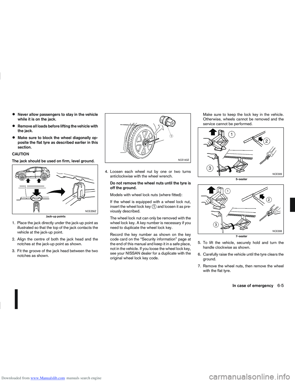
1. Place the jack directly under the jack-up point as illustrated so that the top of the jack contacts the
vehicle at the jack-up point.
2. Align the centre of both the jack head and the notches at the jack-up point as shown.
3. Fit the groove of the jack head between the two notches as shown. 4. Loosen each wheel nut by one or two turns
anticlockwise with the wheel wrench.
Do not remove the wheel nuts until the tyre is
off the ground.
Models with wheel lock nuts (where fitted):
If the wheel is equipped with a wheel lock nut,
insert the wheel lock key
j1 and loosen it as pre-
viously described.
The wheel lock nut can only be removed with the
wheel lock key. A key number is necessary if you
need to duplicate the wheel lock key.
Record the key number as shown on the key
code card on the “Security information” page at
the end of this manual and keep it in a safe place,
not in the vehicle. If you loose the wheel lock key,
see your NISSAN dealer for a duplicate with the
original wheel lock key code. Make sure to keep the lock key in the vehicle.
Otherwise, wheels cannot be removed and the
service cannot be performed.
5. To lift the vehicle, securely hold and turn the handle clockwise as shown.
6. Carefully raise the vehicle until the tyre clears the ground.
7. Remove the wheel nuts, then remove the wheel with the flat tyre.NCE256Z
Jack-up points
NCE143Z
NCE309
5–seater
NCE308
7–seater
In case of emergency6-5
Page 214 of 297
Downloaded from www.Manualslib.com manuals search engine 2. Store the subwoofer (where fitted) as it was origi-nally installed.
3. Install the retainer and replace the floor cover.
7–seater
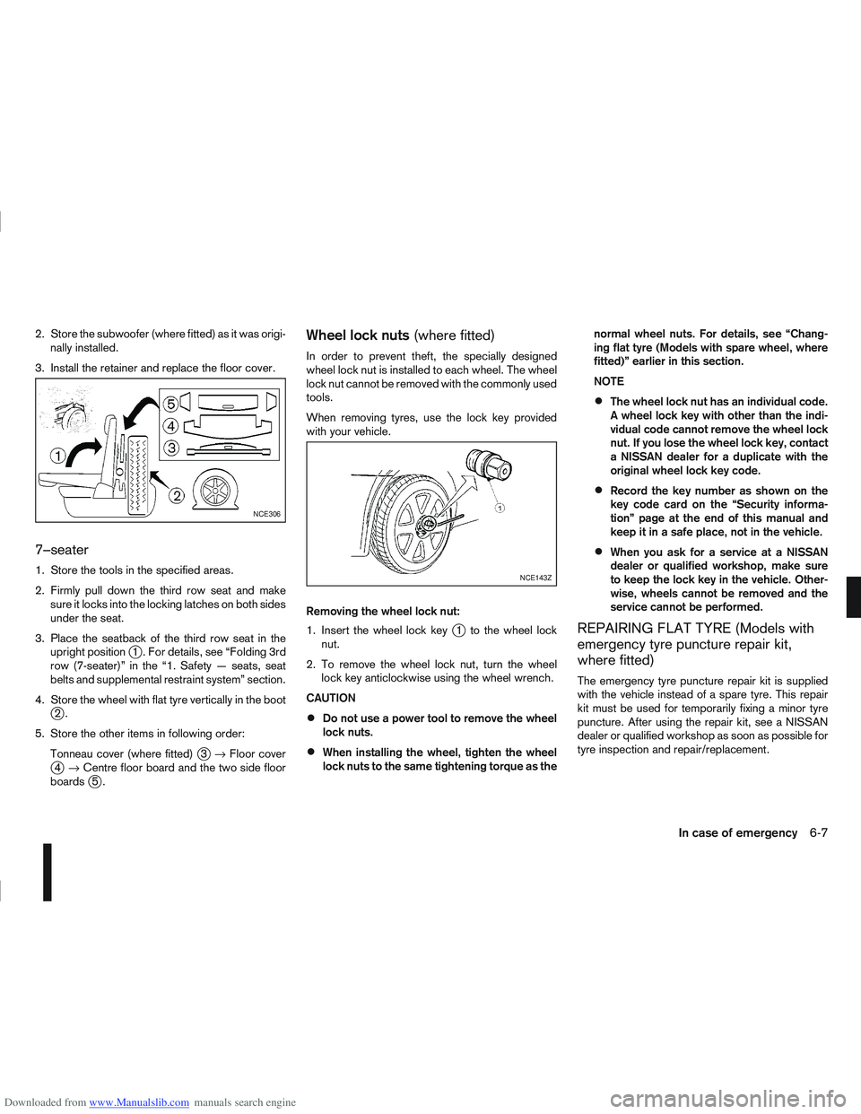
1. Store the tools in the specified areas.
2. Firmly pull down the third row seat and make sure it locks into the locking latches on both sides
under the seat.
3. Place the seatback of the third row seat in the upright position
j1 . For details, see “Folding 3rd
row (7-seater)” in the “1. Safety — seats, seat
belts and supplemental restraint system” section.
4. Store the wheel with flat tyre vertically in the boot
j2.
5. Store the other items in following order: Tonneau cover (where fitted)
j3→ Floor coverj4→ Centre floor board and the two side floor
boardsj5.
Wheel lock nuts (where fitted)
In order to prevent theft, the specially designed
wheel lock nut is installed to each wheel. The wheel
lock nut cannot be removed with the commonly used
tools.
When removing tyres, use the lock key provided
with your vehicle.
Removing the wheel lock nut:
1. Insert the wheel lock key
j1 to the wheel lock
nut.
2. To remove the wheel lock nut, turn the wheel lock key anticlockwise using the wheel wrench.
CAUTION
Do not use a power tool to remove the wheel
lock nuts.
When installing the wheel, tighten the wheel
lock nuts to the same tightening torque as the normal wheel nuts. For details, see “Chang-
ing flat tyre (Models with spare wheel, where
fitted)” earlier in this section.
NOTE
The wheel lock nut has an individual code.
A wheel lock key with other than the indi-
vidual code cannot remove the wheel lock
nut. If you lose the wheel lock key, contact
a NISSAN dealer for a duplicate with the
original wheel lock key code.
Record the key number as shown on the
key code card on the “Security informa-
tion” page at the end of this manual and
keep it in a safe place, not in the vehicle.
When you ask for a service at a NISSAN
dealer or qualified workshop, make sure
to keep the lock key in the vehicle. Other-
wise, wheels cannot be removed and the
service cannot be performed.
REPAIRING FLAT TYRE (Models with
emergency tyre puncture repair kit,
where fitted)
The emergency tyre puncture repair kit is supplied
with the vehicle instead of a spare tyre. This repair
kit must be used for temporarily fixing a minor tyre
puncture. After using the repair kit, see a NISSAN
dealer or qualified workshop as soon as possible for
tyre inspection and repair/replacement.
NCE306
NCE143Z
In case of emergency6-7