display NISSAN QASHQAI 2010 Owner's Manual
[x] Cancel search | Manufacturer: NISSAN, Model Year: 2010, Model line: QASHQAI, Model: NISSAN QASHQAI 2010Pages: 297, PDF Size: 4.09 MB
Page 69 of 297
![NISSAN QASHQAI 2010 Owners Manual Downloaded from www.Manualslib.com manuals search engine [Stop/Start] (where fitted)
The CO2 savings and the engine stop time using
the Stop/Start System are kept in a submenu.
[Trip Saving]
View the NISSAN QASHQAI 2010 Owners Manual Downloaded from www.Manualslib.com manuals search engine [Stop/Start] (where fitted)
The CO2 savings and the engine stop time using
the Stop/Start System are kept in a submenu.
[Trip Saving]
View the](/img/5/56766/w960_56766-68.png)
Downloaded from www.Manualslib.com manuals search engine [Stop/Start] (where fitted)
The CO2 savings and the engine stop time using
the Stop/Start System are kept in a submenu.
[Trip Saving]
View the estimated CO2 exhaust emissions pre-
vented since last reset.
It is possible to reset using the [Reset CO2]
submenu then push the
switch to set to zero.
NOTE
The [Trip Saving] value is the same informa-
tion that is displayed when the engine is auto-
matically stopped by the Stop/Start System.
[Total Saving]
View:
– The estimated CO2 exhaust emissions pre- vented.
– The time that the engine has been stopped by the Stop/Start System.
NOTE
The [Total Saving] values cannot be reset
and show accumulated Stop/Start System
information since the vehicle was built.
For more information, see “Stop/Start System
(where fitted)” in the “5. Starting and driving” sec-
tion.
[Maintenance]
The maintenance intervals of the following remind-
ers can be set or reset:
[Service] for engine oil change service reminder
Select this submenu to view, or reset the dis-
tance driven information or to set an interval
(petrol models).
– View the distance driven information:
Select [Service].
– Set procedure (petrol models only
jA):
1) Select [Service].
2) Select the distance driven/interval informa- tion.
3) Turn the
switch and set the interval (mile-
age) accordingly. For interval (mileage) de-
tails, see the separately provided Warranty
Information and Maintenance booklet.
4) Short press the
switch to confirm the set
interval (mileage).
– Reset procedure after changing engine oil.
CAUTION
Do not perform the reset operation unless
the engine oil has been changed.
For Petrol models
jA:
1) Select [Service].
2) Select [Reset]. 3) Select [Confirm] to confirm the reset of the
distance driven information to zero.
For Diesel models
jB:
1) Select [Service].
2) Press the
switch for more than 2 sec-
onds, then release.
3) Select [Reset].
4) Select [Confirm] to confirm the reset proce- dure.
Alternatively while the oil service message is
displayed (where fitted):
After changing the engine oil: Turn the igni-
tion switch to ON and, while the oil service
message is displayed within 3 seconds, push
both the
andswitches at the same
time for more than 5 seconds.
The display goes blank for 1 second; the de-
fault interval is then displayed; and finally the
display returns to normal.
[Tyre]
Select this submenu to set or reset the distance
for replacing tyres.
[Other]
Select this submenu and set or reset the dis-
tance for replacing or checking other items.
To return to the previous page of the setting mode,
select [Back].
2-20Instruments and controls
Page 70 of 297
![NISSAN QASHQAI 2010 Owners Manual Downloaded from www.Manualslib.com manuals search engine For more information, contact your NISSAN dealer
or qualified workshop.
[Language]
Select the submenu to set the desired language of
the displa NISSAN QASHQAI 2010 Owners Manual Downloaded from www.Manualslib.com manuals search engine For more information, contact your NISSAN dealer
or qualified workshop.
[Language]
Select the submenu to set the desired language of
the displa](/img/5/56766/w960_56766-69.png)
Downloaded from www.Manualslib.com manuals search engine For more information, contact your NISSAN dealer
or qualified workshop.
[Language]
Select the submenu to set the desired language of
the display
[Factory]
Select the submenu to reset the factory settings of
the display.
NOTE
When resetting [Factory], all previous settings
made are changed to default.
CRUISE CONTROL/SPEED LIMITER
INDICATOR (where fitted)
The CRUISE indicator is displayed when the
cruise control main “ON/OFF” switch is pushed.
When the main switch is pushed again, theCRUISE indicator disappears. When the
CRUISE indicator is displayed, the cruise con-
trol system is operational.
The cruise control SET indicator is displayed
while the vehicle speed is controlled by the cruise
control system. If the SET indicator blinks while
the engine is running, it may indicate that the
cruise control system is not functioning properly.
Have the system checked by an NISSAN dealer
or qualified workshop.
For more details, see “Cruise control (where
fitted)” in the “5. Starting and driving” section.
The LIMIT indicator is displayed when the speed
limiter main “ON/OFF” switch is pushed. When
the main switch is pushed again, the LIMIT indi-
cator disappears.
When the LIMIT indicator is displayed, the speed
limiter is operational. The speed limiter is active,
when the SET indicator is displayed.
For more details, see “Speed limiter” in the
“5. Starting and driving” section.
When the trip computer was set before using the
cruise control or speed limiter function, the trip com-
puter menu item
jA is shown together with the
cruise control or speed limiter. See “Trip computer”
earlier in this section
WARNING
In freezing temperatures the washer fluid may
freeze on the windscreen and obscure your vi-
sion. Warm the windscreen with the defroster
before you wash it.
CAUTION
Do not open/release the bonnet when the
front wiper arms are raised from their original
position.
Do not operate the washer continuously for
more than 15 seconds.
Do not operate the washer if the reservoir
tank is empty or frozen.
NIC1550
WIPER AND WASHER SWITCH
Instruments and controls2-21
Page 92 of 297
Downloaded from www.Manualslib.com manuals search engine door outside lock switch until the direction indi-
cators flash to confirm the setting mode. Then
release the driver’s door outside lock switch.
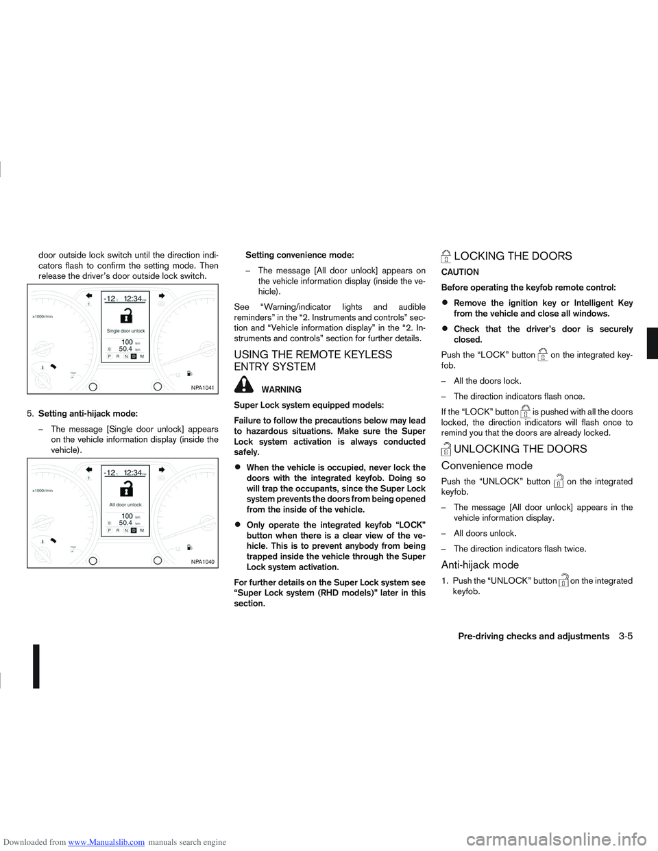
5. Setting anti-hijack mode:
– The message [Single door unlock] appears on the vehicle information display (inside the
vehicle). Setting convenience mode:
– The message [All door unlock] appears on
the vehicle information display (inside the ve-
hicle).
See “Warning/indicator lights and audible
reminders” in the “2. Instruments and controls” sec-
tion and “Vehicle information display” in the “2. In-
struments and controls” section for further details.
USING THE REMOTE KEYLESS
ENTRY SYSTEM
WARNING
Super Lock system equipped models:
Failure to follow the precautions below may lead
to hazardous situations. Make sure the Super
Lock system activation is always conducted
safely.
When the vehicle is occupied, never lock the
doors with the integrated keyfob. Doing so
will trap the occupants, since the Super Lock
system prevents the doors from being opened
from the inside of the vehicle.
Only operate the integrated keyfob “LOCK”
button when there is a clear view of the ve-
hicle. This is to prevent anybody from being
trapped inside the vehicle through the Super
Lock system activation.
For further details on the Super Lock system see
“Super Lock system (RHD models)” later in this
section.
LOCKING THE DOORS
CAUTION
Before operating the keyfob remote control:
Remove the ignition key or Intelligent Key
from the vehicle and close all windows.
Check that the driver’s door is securely
closed.
Push the “LOCK” button
on the integrated key-
fob.
– All the doors lock.
– The direction indicators flash once.
If the “LOCK” button
is pushed with all the doors
locked, the direction indicators will flash once to
remind you that the doors are already locked.
UNLOCKING THE DOORS
Convenience mode
Push the “UNLOCK” buttonon the integrated
keyfob.
– The message [All door unlock] appears in the vehicle information display.
– All doors unlock.
– The direction indicators flash twice.
Anti-hijack mode
1. Push the “UNLOCK” buttonon the integrated
keyfob.
NPA1041
NPA1040
Pre-driving checks and adjustments3-5
Page 93 of 297
![NISSAN QASHQAI 2010 Owners Manual Downloaded from www.Manualslib.com manuals search engine – The message [Single door unlock] appears inthe vehicle information display.
– Only the driver’s door unlocks.
– The direction indicat NISSAN QASHQAI 2010 Owners Manual Downloaded from www.Manualslib.com manuals search engine – The message [Single door unlock] appears inthe vehicle information display.
– Only the driver’s door unlocks.
– The direction indicat](/img/5/56766/w960_56766-92.png)
Downloaded from www.Manualslib.com manuals search engine – The message [Single door unlock] appears inthe vehicle information display.
– Only the driver’s door unlocks.
– The direction indicators flash twice, quickly.
2. Push the “UNLOCK” button
on the integrated
keyfob again.
– All doors unlock.
– The direction indicators flash twice.
Auto-relock:
An auto-relock function will operate 2 minutes after
a full or partial unlock, if no further user action is
taken. The auto-relock will be cancelled if any door
is opened or the key is inserted into the ignition.
KEYFOB OPERATION FAILURE
The keyfob may not work properly if:
The keyfob battery is low. See “Integrated key-
fob/Intelligent Key battery replacement” in the
“8. Maintenance and do-it-yourself” section for
keyfob battery replacement instructions and the
required battery type.
The locking/unlocking system has been used
continuously. An anti lock-abuse system pre-
vents the lock motors from overheating and dis-
ables the keyfob locking operation for a short
period of time if the system is used continuously.
The door handle is being pulled while the
keyfob is being operated.
The vehicle’s battery is dead. NOTE
See Intelligent Key detection warning, Intelligent
Key low battery warning or Intelligent Key system
fault warning in “Vehicle information display” ear-
lier in this section for more information.
The Intelligent Key system is a convenient keyless
entry system that allows you to operate your vehicle
without using an actual key.
WARNING
Radio waves could adversely affect electric medi-
cal equipment. Those who use a pacemaker
should contact the electric medical equipment
manufacturer for the possible influences before
use.
INTELLIGENT KEY OPERATING
RANGE
The Intelligent Key functions can only be used when
the Intelligent Key is within the specified operating
range from the request switch
j1.
When the Intelligent Key battery is discharged or
strong radio waves are present near the operating
location, the Intelligent Key system’s operating
range becomes narrower, and the Intelligent Key
may not function properly.
NPA1042NPA1018
INTELLIGENT KEY SYSTEM
(where fitted)
3-6Pre-driving checks and adjustments
Page 95 of 297
Downloaded from www.Manualslib.com manuals search engine Locking the doors
1. Make sure you have the Intelligent Key with youwhen exiting the vehicle.
2. Close all doors.
3. Press any of the outside lock switches (front doors or back door).
– All the doors lock.
– The direction indicators flash once.
– Super Lock system equipped models: The Su-
per Lock system will be activated
CAUTION
Do not leave the duplicate Intelligent Key inside
the vehicle as the locking procedure logic will
not work.
NOTE
If the Intelligent Key is left in the vehicle and the
door/back door outside lock switch is pressed, a
buzzer will sound, warning the owner that the
Intelligent Key has been left inside the vehicle.
Unlocking the doors
For details on setting the unlock mode (anti-hijack or
convenience mode) see “Switching from Conve-
nience mode to Anti-hijack mode” earlier in this sec-
tion. Convenience mode:
Push the door/back door outside lock switch.
– All doors unlock.
– The direction indicators flash twice.
– The message [All door unlock] appears in the
vehicle information display.
Anti-hijack mode:
1. Push the door/back door outside lock switch.
– The corresponding door unlocks
– The direction indicators flash twice quickly
– The message [Single door unlock] appears in the vehicle information display.
2. Push the door/back door outside lock switch again within 5 seconds.
– All doors unlock.
– The direction indicators flash twice, slowly.
NOTE
External interference may impair the Intelligent
Key’s operation. In this case, use the emergency
key located in the Intelligent Key integrated key-
fob. See “Door locks” later in this section for fur-
ther details.
CAUTION
Make sure the Intelligent Key battery is in good
condition. Note that battery life may vary de-
pending on condition, amount of use, ambi-
ent temperature, etc.
The Intelligent Key contains a miniature radio
transmitter that may be affected when placed
near metal objects.
Keep the Intelligent Key away from mobile
phones, laptop computers and other metal
objects or electronics.
STARTING THE ENGINE WITH THE
INTELLIGENT KEY
See “Ignition knob (where fitted)” in the “5. Starting
and driving” section.
CAUTION
Make sure you carry the Intelligent Key with
you when starting and driving the vehicle.
If the Intelligent Key is too far away from the
passenger compartment, the vehicle may not
start. See “Intelligent Key operating range” in
the “3. Pre-driving checks and adjustments”
section
3-8Pre-driving checks and adjustments
Page 108 of 297
Downloaded from www.Manualslib.com manuals search engine 4Display screen, heater and air conditioner,
and audio system
Display screen, heater and air conditioner,
and
audio system
Rear-view monitor (where fitted)............................... 4-2
How to read the displayed lines .......................... 4-2
Rear-view monitor setting.................................... 4-3
Operating tips..................................................... 4-3
Around view monitor (where fitted)........................... 4-4 Operation ........................................................... 4-6
Guide lines ......................................................... 4-7
Difference between predictive and actual
distances ............................................................ 4-9
How to adjust the screen view ............................ 4-11
Operating tips..................................................... 4-11
Vents ....................................................................... 4-12 Side and centre vents ......................................... 4-12
High level vent (where fitted) ............................... 4-12
Heater and air conditioner operation ........................ 4-12 Manual air conditioner......................................... 4-13
Automatic air conditioner (where fitted) ............... 4-18
Audio system ........................................................... 4-21 Audio operation precautions ............................... 4-21
Antenna .............................................................. 4-22
LW-MW-FM radio with CD player or 6 CD
changer ................................................................... 4-23 Anti-theft system ................................................. 4-24
Audio main operation .......................................... 4-24
Radio operation .................................................. 4-24
MENU button...................................................... 4-27 Compact Disc (CD) operation ............................ 4-27
AUX socket ........................................................ 4-29
Bluetooth® mobile phone feature ........................ 4-29
FM AM radio with CD player.................................... 4-30 Anti-theft system ................................................. 4-31
Audio main operation .......................................... 4-31
Radio operation .................................................. 4-32
SETUP button .................................................... 4-33
Compact Disc (CD) operation ............................ 4-35
AUX socket ........................................................ 4-36
USB Memory operation (where fitted) ................. 4-37
iPod® player operation (where fitted) .................. 4-37
Bluetooth® operation.......................................... 4-39
NISSAN Connect (where fitted) ............................... 4-43
Steering wheel switch for audio control (where
fitted) ....................................................................... 4-43 Main operation .................................................... 4-43
Car phone or CB radio ............................................ 4-44
Mobile phone integration for LW-MW-FM radio
with CD player or 6 CD changer (Type A) ................ 4-44 Bluetooth® mobile phone feature ........................ 4-44
Mobile phone integration for FM AM radio with
CD player ................................................................ 4-52 Bluetooth® mobile phone feature ........................ 4-52
Hands-free telephone control .............................. 4-53
Steering wheel switches (where fitted) ................ 4-55
Page 109 of 297
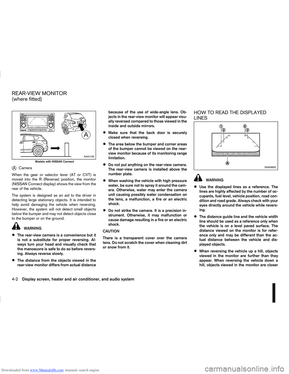
Downloaded from www.Manualslib.com manuals search engine jACamera
When the gear or selector lever (AT or CVT) is
moved into the R (Reverse) position, the monitor
(NISSAN Connect display) shows the view from the
rear of the vehicle.
The system is designed as an aid to the driver in
detecting large stationary objects. It is intended to
help avoid damaging the vehicle when reversing.
However, the system will not detect small objects
below the bumper and may not detect objects close
to the bumper or on the ground.
WARNING
The rear-view camera is a convenience but it
is not a substitute for proper reversing. Al-
ways turn your head and visually check that
the manoeuvre is safe to do so before revers-
ing. Always reverse slowly.
The distance from the objects viewed in the
rear-view monitor differs from actual distance because of the use of wide-angle lens. Ob-
jects in the rear-view monitor will appear visu-
ally reversed compared to those viewed in the
inside and outside mirrors.
Make sure that the back door is securely
closed when reversing.
The area below the bumper and corner areas
of the bumper cannot be viewed on the rear-
view monitor because of its monitoring range
limitation.
Do not put anything on the rear-view camera.
The rear-view camera is installed above the
number plate.
When washing the vehicle with high pressure
water, be sure not to spray it around the cam-
era. Otherwise, water may enter the camera
unit causing possibly water condensation on
the lens, a malfunction, a fire or an electric
shock.
Do not strike the camera. It is a precision in-
strument. Otherwise, it may malfunction or
cause damage resulting in a fire or an electric
shock.
CAUTION
There is a transparent cover over the camera
lens. Do not scratch the cover when cleaning dirt
or snow from it.
HOW TO READ THE DISPLAYED
LINES
WARNING
Use the displayed lines as a reference. The
lines are highly affected by the number of oc-
cupants, fuel level, vehicle position, road con-
dition and road grade. Always check with your
eyes directly around the vehicle while revers-
ing.
The distance guide line and the vehicle width
line should be used as a reference only when
the vehicle is on a level paved surface. The
distance viewed on the monitor is for refer-
ence only and may be different than the ac-
tual distance between the vehicle and dis-
played objects.
When reversing the vehicle up a hill, objects
viewed in the monitor are further than they
appear. When reversing the vehicle down a
hill, objects viewed in the monitor are closer
NAA1120
Models with NISSAN Connect
SAA0889Z
REAR-VIEW MONITOR
(where fitted)
4-2Display screen, heater and air conditioner, and audio system
Page 110 of 297
Downloaded from www.Manualslib.com manuals search engine than they appear. Use the inside mirror or
glance over your shoulder to properly judge
distances to other objects.
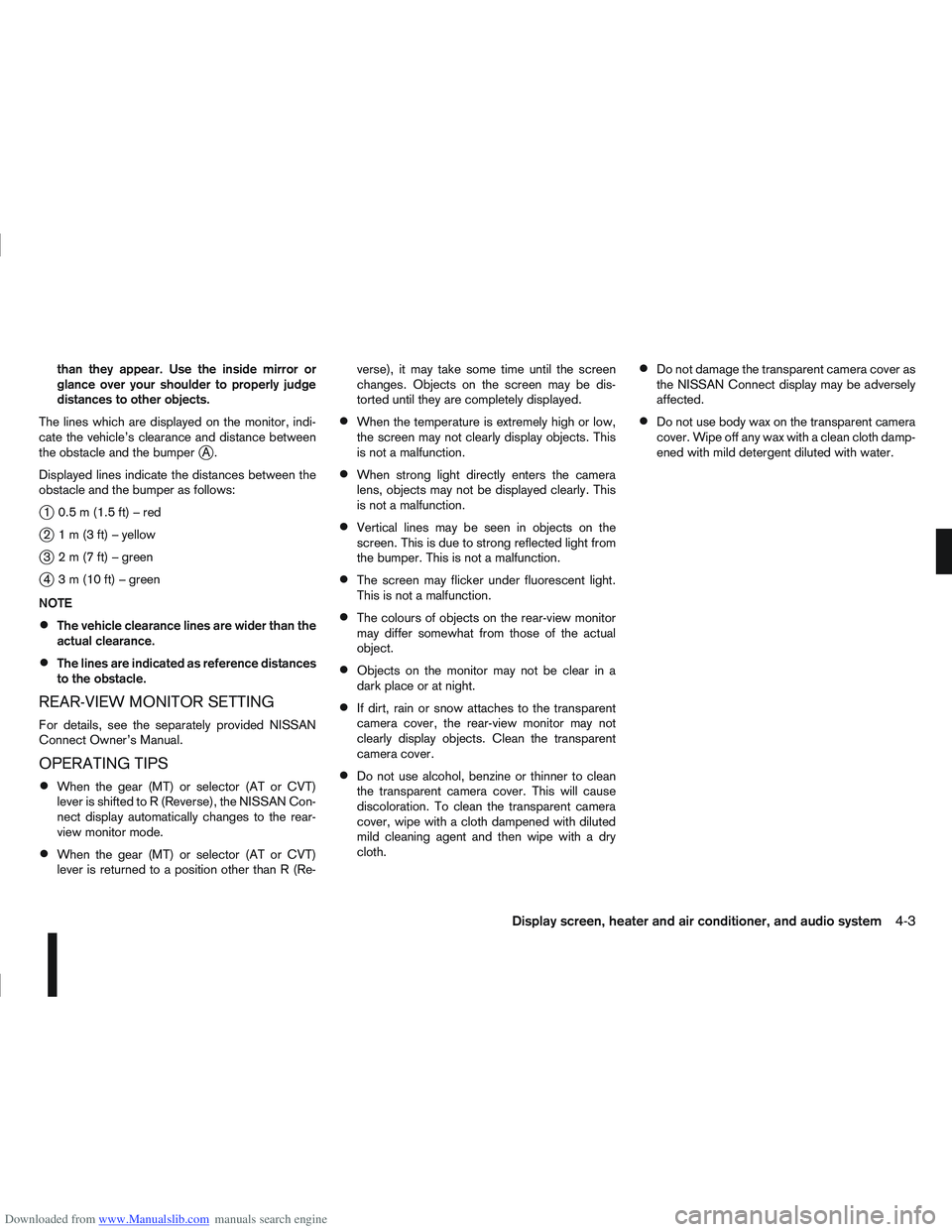
The lines which are displayed on the monitor, indi-
cate the vehicle’s clearance and distance between
the obstacle and the bumper
jA.
Displayed lines indicate the distances between the
obstacle and the bumper as follows:
j1 0.5m(1.5ft)–red
j2 1m(3ft)–yellow
j3 2m(7ft)–green
j4 3m(10ft)–green
NOTE
The vehicle clearance lines are wider than the
actual clearance.
The lines are indicated as reference distances
to the obstacle.
REAR-VIEW MONITOR SETTING
For details, see the separately provided NISSAN
Connect Owner’s Manual.
OPERATING TIPS
When the gear (MT) or selector (AT or CVT)
lever is shifted to R (Reverse), the NISSAN Con-
nect display automatically changes to the rear-
view monitor mode.
When the gear (MT) or selector (AT or CVT)
lever is returned to a position other than R (Re- verse), it may take some time until the screen
changes. Objects on the screen may be dis-
torted until they are completely displayed.
When the temperature is extremely high or low,
the screen may not clearly display objects. This
is not a malfunction.
When strong light directly enters the camera
lens, objects may not be displayed clearly. This
is not a malfunction.
Vertical lines may be seen in objects on the
screen. This is due to strong reflected light from
the bumper. This is not a malfunction.
The screen may flicker under fluorescent light.
This is not a malfunction.
The colours of objects on the rear-view monitor
may differ somewhat from those of the actual
object.
Objects on the monitor may not be clear in a
dark place or at night.
If dirt, rain or snow attaches to the transparent
camera cover, the rear-view monitor may not
clearly display objects. Clean the transparent
camera cover.
Do not use alcohol, benzine or thinner to clean
the transparent camera cover. This will cause
discoloration. To clean the transparent camera
cover, wipe with a cloth dampened with diluted
mild cleaning agent and then wipe with a dry
cloth.
Do not damage the transparent camera cover as
the NISSAN Connect display may be adversely
affected.
Do not use body wax on the transparent camera
cover. Wipe off any wax with a clean cloth damp-
ened with mild detergent diluted with water.
Display screen, heater and air conditioner, and audio system4-3
Page 111 of 297
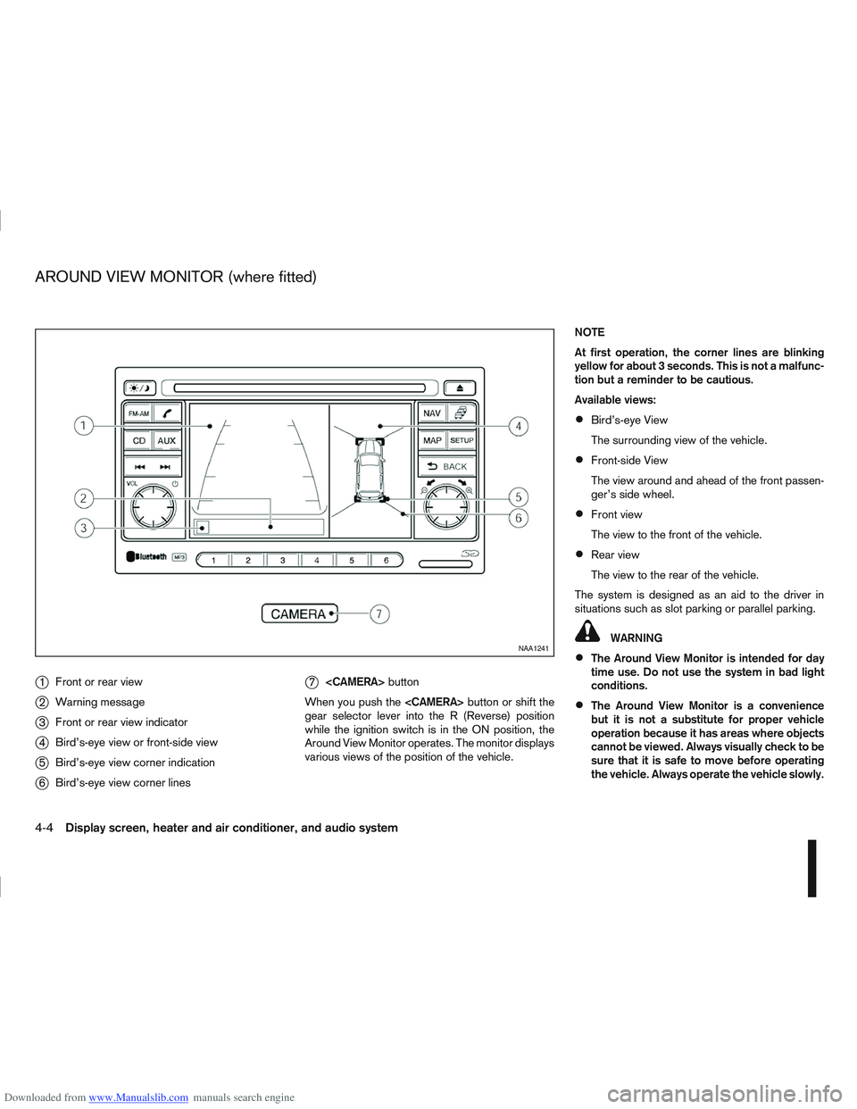
Downloaded from www.Manualslib.com manuals search engine j1Front or rear view
j2Warning message
j3Front or rear view indicator
j4Bird’s-eye view or front-side view
j5Bird’s-eye view corner indication
j6Bird’s-eye view corner lines
j7
button
When you push the
gear selector lever into the R (Reverse) position
while the ignition switch is in the ON position, the
Around View Monitor operates. The monitor displays
various views of the position of the vehicle. NOTE
At first operation, the corner lines are blinking
yellow for about 3 seconds. This is not a malfunc-
tion but a reminder to be cautious.
Available views:
Bird’s-eye View
The surrounding view of the vehicle.
Front-side View
The view around and ahead of the front passen-
ger’s side wheel.
Front view
The view to the front of the vehicle.
Rear view
The view to the rear of the vehicle.
The system is designed as an aid to the driver in
situations such as slot parking or parallel parking.
WARNING
The Around View Monitor is intended for day
time use. Do not use the system in bad light
conditions.
The Around View Monitor is a convenience
but it is not a substitute for proper vehicle
operation because it has areas where objects
cannot be viewed. Always visually check to be
sure that it is safe to move before operating
the vehicle. Always operate the vehicle slowly.
NAA1241
AROUND VIEW MONITOR (where fitted)
4-4Display screen, heater and air conditioner, and audio system
Page 112 of 297
Downloaded from www.Manualslib.com manuals search engine Do not use the Around View Monitor with the
outside mirror in the stored position, and
make sure that the back door is securely
closed when operating the vehicle using the
Around View Monitor.
The distance between objects viewed on the
Around View Monitor differs from the actual
distance.
The cameras are installed above the front
grille, the outside mirrors and above the rear
number plate. Do not put anything on or cover
the cameras.
When washing the vehicle with high-pressure
water, be sure not to spray it around the cam-
eras. Otherwise, water may enter the camera
unit causing water condensation on the lens,
a malfunction, fire or an electric shock.
Do not strike the cameras. They are precision
instruments. Doing so could cause a malfunc-
tion or cause damage resulting in a fire or an
electric shock.
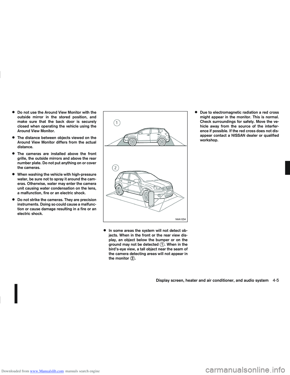
In some areas the system will not detect ob-
jects. When in the front or the rear view dis-
play, an object below the bumper or on the
ground may not be detected
j1 . When in the
bird’s-eye view, a tall object near the seam of
the camera detecting areas will not appear in
the monitor
j2.
Due to electromagnetic radiation a red cross
might appear in the monitor. This is normal.
Check surroundings for safety. Move the ve-
hicle away from the source of the interfer-
ence if possible. If the red cross does not dis-
appear contact a NISSAN dealer or qualified
workshop.
NAA1234
Display screen, heater and air conditioner, and audio system4-5