brake light NISSAN QASHQAI 2013 User Guide
[x] Cancel search | Manufacturer: NISSAN, Model Year: 2013, Model line: QASHQAI, Model: NISSAN QASHQAI 2013Pages: 297, PDF Size: 4.09 MB
Page 58 of 297
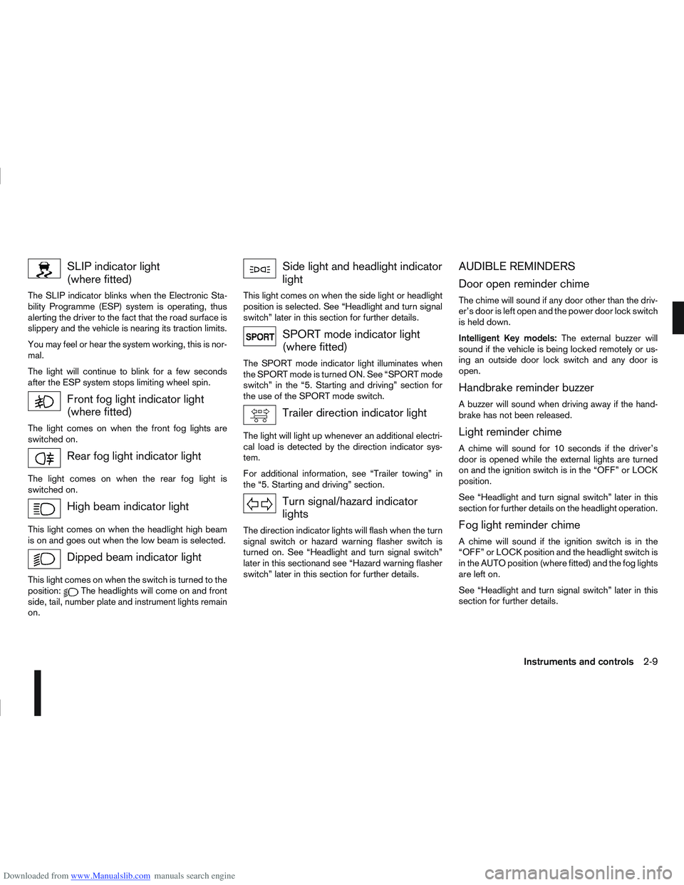
Downloaded from www.Manualslib.com manuals search engine SLIP indicator light
(where fitted)
The SLIP indicator blinks when the Electronic Sta-
bility Programme (ESP) system is operating, thus
alerting the driver to the fact that the road surface is
slippery and the vehicle is nearing its traction limits.
You may feel or hear the system working, this is nor-
mal.
The light will continue to blink for a few seconds
after the ESP system stops limiting wheel spin.
Front fog light indicator light
(where fitted)
The light comes on when the front fog lights are
switched on.
Rear fog light indicator light
The light comes on when the rear fog light is
switched on.
High beam indicator light
This light comes on when the headlight high beam
is on and goes out when the low beam is selected.
Dipped beam indicator light
This light comes on when the switch is turned to the
position:The headlights will come on and front
side, tail, number plate and instrument lights remain
on.
Side light and headlight indicator
light
This light comes on when the side light or headlight
position is selected. See “Headlight and turn signal
switch” later in this section for further details.
SPORT mode indicator light
(where fitted)
The SPORT mode indicator light illuminates when
the SPORT mode is turned ON. See “SPORT mode
switch” in the “5. Starting and driving” section for
the use of the SPORT mode switch.
Trailer direction indicator light
The light will light up whenever an additional electri-
cal load is detected by the direction indicator sys-
tem.
For additional information, see “Trailer towing” in
the “5. Starting and driving” section.
Turn signal/hazard indicator
lights
The direction indicator lights will flash when the turn
signal switch or hazard warning flasher switch is
turned on. See “Headlight and turn signal switch”
later in this sectionand see “Hazard warning flasher
switch” later in this section for further details.
AUDIBLE REMINDERS
Door open reminder chime
The chime will sound if any door other than the driv-
er’s door is left open and the power door lock switch
is held down.
Intelligent Key models: The external buzzer will
sound if the vehicle is being locked remotely or us-
ing an outside door lock switch and any door is
open.
Handbrake reminder buzzer
A buzzer will sound when driving away if the hand-
brake has not been released.
Light reminder chime
A chime will sound for 10 seconds if the driver’s
door is opened while the external lights are turned
on and the ignition switch is in the “OFF” or LOCK
position.
See “Headlight and turn signal switch” later in this
section for further details on the headlight operation.
Fog light reminder chime
A chime will sound if the ignition switch is in the
“OFF” or LOCK position and the headlight switch is
in the AUTO position (where fitted) and the fog lights
are left on.
See “Headlight and turn signal switch” later in this
section for further details.
Instruments and controls2-9
Page 103 of 297
Downloaded from www.Manualslib.com manuals search engine the fuel system and emission control system.
An incorrect cap can result in a serious mal-
function and possible injury.
CAUTION
If fuel is spilled on the vehicle body, flush it away
with water to avoid paint damage.
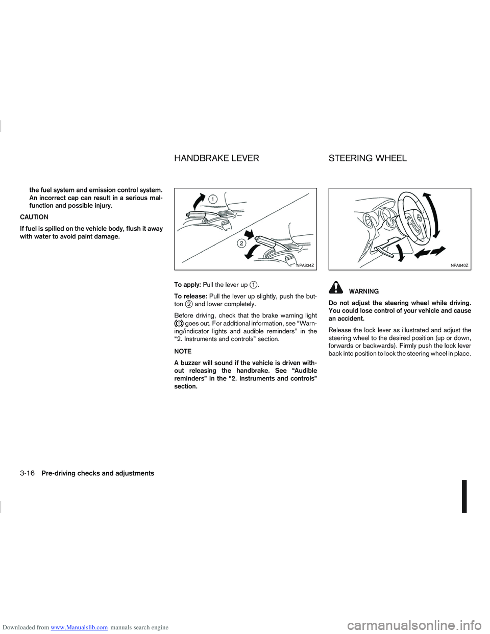
To apply:Pull the lever up
j1.
To release: Pull the lever up slightly, push the but-
ton
j2 and lower completely.
Before driving, check that the brake warning light
goes out. For additional information, see “Warn-
ing/indicator lights and audible reminders” in the
“2. Instruments and controls” section.
NOTE
A buzzer will sound if the vehicle is driven with-
out releasing the handbrake. See “Audible
reminders” in the “2. Instruments and controls”
section.
WARNING
Do not adjust the steering wheel while driving.
You could lose control of your vehicle and cause
an accident.
Release the lock lever as illustrated and adjust the
steering wheel to the desired position (up or down,
forwards or backwards). Firmly push the lock lever
back into position to lock the steering wheel in place.
NPA834ZNPA840Z
HANDBRAKE LEVER STEERING WHEEL
3-16Pre-driving checks and adjustments
Page 118 of 297
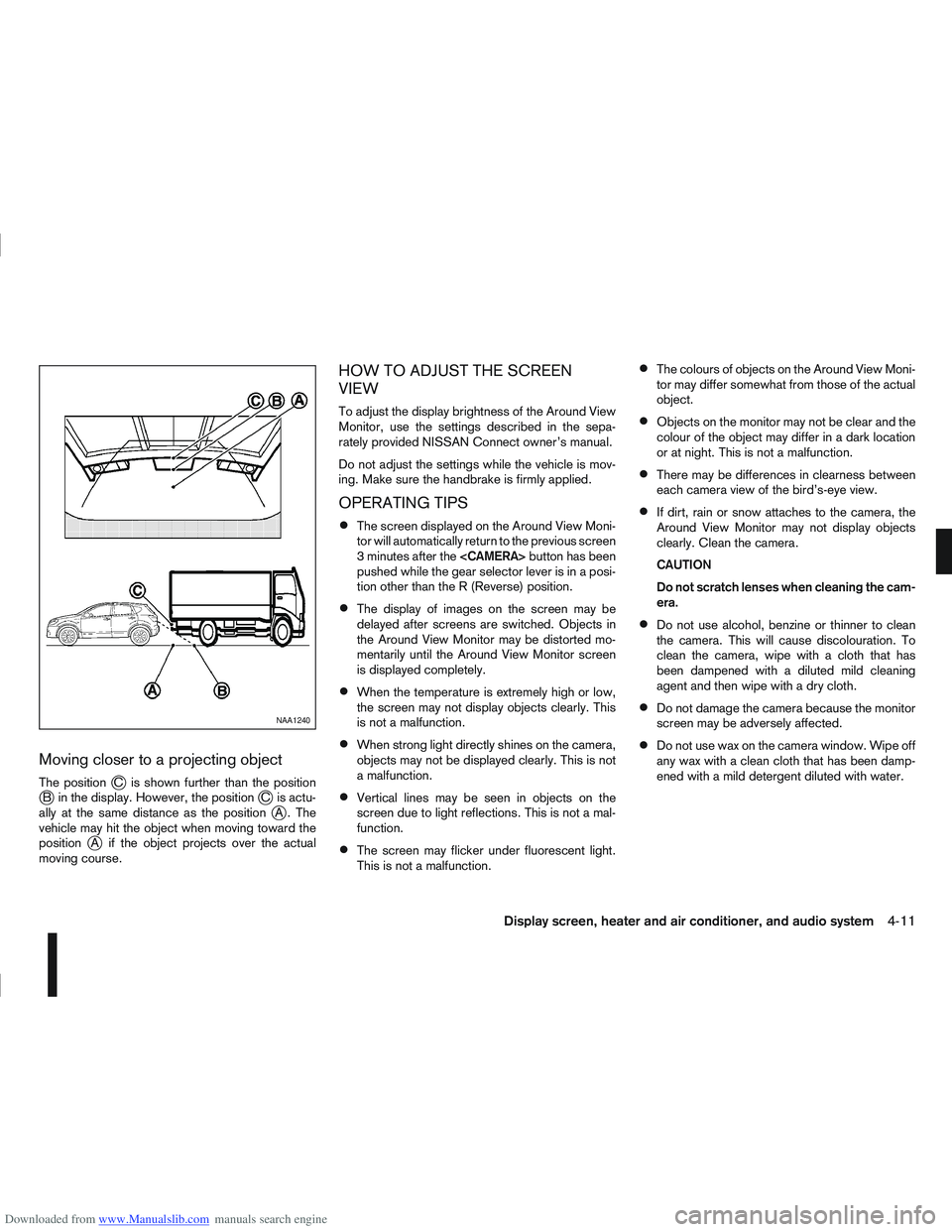
Downloaded from www.Manualslib.com manuals search engine Moving closer to a projecting object
The positionjC is shown further than the positionjB in the display. However, the positionjC is actu-
ally at the same distance as the positionjA . The
vehicle may hit the object when moving toward the
position
jA if the object projects over the actual
moving course.
HOW TO ADJUST THE SCREEN
VIEW
To adjust the display brightness of the Around View
Monitor, use the settings described in the sepa-
rately provided NISSAN Connect owner’s manual.
Do not adjust the settings while the vehicle is mov-
ing. Make sure the handbrake is firmly applied.
OPERATING TIPS
The screen displayed on the Around View Moni-
tor will automatically return to the previous screen
3 minutes after the
pushed while the gear selector lever is in a posi-
tion other than the R (Reverse) position.
The display of images on the screen may be
delayed after screens are switched. Objects in
the Around View Monitor may be distorted mo-
mentarily until the Around View Monitor screen
is displayed completely.
When the temperature is extremely high or low,
the screen may not display objects clearly. This
is not a malfunction.
When strong light directly shines on the camera,
objects may not be displayed clearly. This is not
a malfunction.
Vertical lines may be seen in objects on the
screen due to light reflections. This is not a mal-
function.
The screen may flicker under fluorescent light.
This is not a malfunction.
The colours of objects on the Around View Moni-
tor may differ somewhat from those of the actual
object.
Objects on the monitor may not be clear and the
colour of the object may differ in a dark location
or at night. This is not a malfunction.
There may be differences in clearness between
each camera view of the bird’s-eye view.
If dirt, rain or snow attaches to the camera, the
Around View Monitor may not display objects
clearly. Clean the camera.
CAUTION
Do not scratch lenses when cleaning the cam-
era.
Do not use alcohol, benzine or thinner to clean
the camera. This will cause discolouration. To
clean the camera, wipe with a cloth that has
been dampened with a diluted mild cleaning
agent and then wipe with a dry cloth.
Do not damage the camera because the monitor
screen may be adversely affected.
Do not use wax on the camera window. Wipe off
any wax with a clean cloth that has been damp-
ened with a mild detergent diluted with water.
NAA1240
Display screen, heater and air conditioner, and audio system4-11
Page 161 of 297
![NISSAN QASHQAI 2013 User Guide Downloaded from www.Manualslib.com manuals search engine 2. Turn the<TUNE/MENU> dial and scroll down to
[Phone Book] then press <ENTER>.
3. Scroll down through the list, select the appropri- ate conta](/img/5/56763/w960_56763-160.png "NISSAN QASHQAI 2013 User Guide Downloaded from www.Manualslib.com manuals search engine 2. Turn the<TUNE/MENU> dial and scroll down to
[Phone Book] then press <ENTER>.
3. Scroll down through the list, select the appropri- ate conta")
Downloaded from www.Manualslib.com manuals search engine 2. Turn the
[Phone Book] then press
3. Scroll down through the list, select the appropri- ate contact name (highlighted), and press
4. A following screen will show the number to be dialled. If correct, press
the number.
If the contact has more numbers assigned for
(home),(mobile), or(office), scroll,
and select the appropriate number to dial.
Alternatively, the quick search mode can be used as
follows:
1. Press
2. Turn the
betic or numerical letter of the contact name.
Once highlighted, press
letter.
3. The display will show the corresponding contact name(s). Where necessary, use the
priate contact name to call.
4. A following screen will show the number to be dialled. If correct, press
the number. Manually dialling a phone number:
WARNING
Park the vehicle in a safe location, and apply the
handbrake before making a call.
To dial a phone number manually use the audio sys-
tem display (virtual keyboard pad) as follows:
1. Press <
>, and turn the
highlight [Call Number].
2. Press
3. Turn the
select each number of the phone number. Once
highlighted, press
selection.
To delete the last number entered scroll to the
[←] (Backspace) symbol, and once highlighted
press
leted. Pressing
each subsequent number. 4. After entering the last number, scroll to the [
]
symbol, and press
dial the number.
Call Lists:
A number from the dialled, received, or missed call
lists can also be used to make a call.
Dialled call
Use the dialled call mode to make a call which is
based on the list of outgoing (dialled) calls.
Received call
Use the received call mode to make a call which
is based on the list of received calls.
Missed call
Use the missed call mode to make a call which
is based on the list of missed calls.
1. Press <
>, and select [Call Lists].
2. Turn the
and press
3. Scroll to the preferred phone number then press
>to dial the number.
NAA1198
4-54Display screen, heater and air conditioner, and audio system
Page 165 of 297
Downloaded from www.Manualslib.com manuals search engine During the first 1,600 km (1,000 miles), follow these
recommendations for the future reliability and
economy of your new vehicle. Failure to follow the
recommendations may result in shortened engine
life and reduced engine performance.
Avoid driving for long periods at a constant
speed, either fast or slow.
Do not accelerate at full throttle in any gear.
Avoid quick starts.
Avoid hard braking as much as possible.
Do not tow a trailer during the first 800 km (500
miles).
NOTE
Models with K9K diesel engine will achieve top
performance only after approximately 5,000 km
(3,000 miles).
WARNING
The driving characteristics of your vehicle can be
changed remarkably by any additional load and
its distribution as well as by adding optional
equipment (trailer couplings, roof racks, etc.).
Your driving style and speed have to be adjusted
accordingly. Especially when carrying heavy
loads, your speed must be reduced adequately.
Make sure the area around the vehicle is free of
obstacles.
Check fluid levels such as engine oil, coolant,
brake and clutch fluid, and window washer fluid
as frequently as possible, at least whenever you
refuel.
Visually inspect tyres for their appearance and
condition. Also check the tyre pressure for
proper inflation.
Maintenance items in the “8. Maintenance and
do-it-yourself” section should be checked peri-
odically.
Check that all windows and light lenses are
clean.
Check that all doors are closed.
Position the seat and adjust the head restraints.
Adjust the inside and outside mirrors.
Fasten your seat belt and ask all passengers to
do likewise.
Check the operation of the warning/indicator
lights when the ignition switch is turned to the
ON position.
Do not place hard or heavy objects on the dash-
board or rear parcel shelf in order to prevent
injury in the event of a sudden stop.
RUNNING-IN SCHEDULE BEFORE STARTING THE ENGINE
5-2Starting and driving
Page 170 of 297
Downloaded from www.Manualslib.com manuals search engine unlock the steering wheel, insert the ignition key and
turn it gently while rotating the steering wheel slightly
right and left.
The ignition key can only be removed when the
switch is in the LOCK position (Normal parking po-
sition) (0).
AUTOMATIC TRANSMISSION OR
CONTINUOUSLY VARIABLE
TRANSMISSION
On Automatic Transmission (AT) or Continuously
Variable Transmission (CVT) models, the ignition
lock is designed so that the key cannot be turned to
LOCK and removed until the selector lever is moved
to the P (Park) position.
When removing the key from the LOCK position of
the ignition switch, make sure that the selector lever
is in the P (Park) position.
The selector lever can only be moved from the P
(Park) position when the ignition switch is in the ON
position and the footbrake pedal is depressed.
To remove the key from the ignition switch:
1. Move the selector lever into the P (Park) posi-tion.
2. Turn the key to the LOCK position.
3. Remove the key from the ignition switch.
If the key is removed from the ignition switch, the
selector lever cannot be moved from the P (Park)
position. When the key cannot be turned toward the LOCK
position, proceed as follows to remove the key:
1. Move the selector lever into the P (Park) posi-
tion.
2. Turn the key slightly in the ON direction.
3. Turn the key towards the LOCK position.
4. Remove the key.
STEERING LOCK
To lock the steering wheel
1. Turn the key to the LOCK position.
2. Remove the key from the ignition switch.
3. Turn the steering wheel 1/6 of a turn clockwise from the straight up position.
To unlock the steering wheel
1. Insert the key into the ignition switch.
2. Gently turn the key while rotating the steeringwheel slightly right and left.
KEY POSITIONS
LOCK (Normal parking position) (0)
The ignition key can only be removed when in this
position.
The steering lock can only be locked in this position.
“OFF” (1)
The engine is turned off without locking the steering
wheel.
Acc (Accessories) (2)
This position activates electrical accessories, such
as the radio, when the engine is not running.
ON (Normal operating position) (3)
This position turns on the ignition system and elec-
trical accessories.
START (4)
The engine starter activates and the engine will start.
As soon as the engine has started, release the key
immediately. It will return to the ON position.
NOTE
For vehicles fitted with Stop/Start System:
When the engine is automatically stopped by the
Stop/Start System the ignition switch can still be
operated as usual.
At the end of a journey turn the ignition OFF to
avoid a flat battery. The Stop/Start System does
not automatically turn ignition off.
NISSAN ANTI-THEFT SYSTEM (NATS)
The NISSAN Anti Theft System (NATS)* will stop
the engine if someone tries to start the engine with-
out using the registered NATS key.
* Immobilizer
If you failed to start the engine using the NATS Key,
turn the ignition knob to the LOCK position, wait for
5 seconds and turn the key to the START position
again to start the engine.
Starting and driving5-7
Page 173 of 297
Downloaded from www.Manualslib.com manuals search engine EMERGENCY KEY – INTELLIGENT
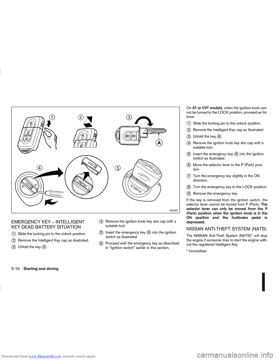
KEY DEAD BATTERY SITUATION
j
1Slide the locking pin to the unlock position.
j2Remove the Intelligent Key cap as illustrated.
j3Unfold the keyjA.
j4Remove the ignition knob key slot cap with a
suitable tool.
j5Insert the emergency keyjA into the ignition
switch as illustrated.
j6 Proceed with the emergency key as described
in “Ignition switch” earlier in this section. On
AT or CVT models, when the ignition knob can-
not be turned to the LOCK position, proceed as fol-
lows:
j1 Slide the locking pin to the unlock position.
j2Remove the Intelligent Key cap as illustrated.
j3Unfold the keyjA.
j4Remove the ignition knob key slot cap with a
suitable tool.
j5Insert the emergency keyjA into the ignition
switch as illustrated.
j6 Move the selector lever to the P (Park) posi-
tion.
j7Turn the emergency key slightly in the ON
direction.
j8Turn the emergency key to the LOCK position.
j9Remove the emergency key.
If the key is removed from the ignition switch, the
selector lever cannot be moved from P (Park). The
selector lever can only be moved from the P
(Park) position when the ignition knob is in the
ON position and the footbrake pedal is
depressed.
NISSAN ANTI-THEFT SYSTEM (NATS)
The NISSAN Anti-Theft System (NATS)* will stop
the engine if someone tries to start the engine with-
out the registered Intelligent Key.
* Immobilizer
NSD291
5-10Starting and driving
Page 174 of 297
Downloaded from www.Manualslib.com manuals search engine If you failed to start the engine using the NATS Intel-
ligent Key, turn the ignition knob to the LOCK posi-
tion, wait for 5 seconds and turn the knob to the
START position again to start the engine.
For additional information, see “NISSAN Anti-Theft
System (NATS)” in the “3. Pre-driving checks and
adjustments” section.1. Apply the handbrake.
2.
Manual transmission models:
Move the gear lever to N (Neutral) position, and
depress the clutch pedal to the floor while start-
ing the engine.
Automatic transmission or Continuously vari-
able transmission models:
Depress the brake pedal and move the selector
lever to the P (Park) or N (Neutral) position.
(P position is preferred). NOTE
The starter is designed not to operate if the
selector lever is out of the P (Park) or N (Neu-
tral) position.
3. Models without Intelligent Key: Rotate the steering wheel left to right to release
the ignition lock whilst turning the ignition switch
to the ON position.
Models with Intelligent key:
MT models – keep the clutch pedal
depressed and/or depress the brake pedal
then:
AT or CVT models – depress the brake pedal
then:
1) Push the ignition knob.
2) Rotate the steering wheel left to right to release the ignition lock whilst turning the
ignition knob to the ON position. CAUTION
Make sure you carry the Intelligent Key with
you when operating the vehicle.
If the Intelligent Key is too far away from
the driver, the vehicle may not start.
4. For diesel engine models: Wait until the glow indicator light
goes out.
5. Crank the engine with your foot on the brake pedal, not on the accelerator pedal , by turning
the ignition switch to START.
6. Release the ignition switch when the engine starts. If the engine starts, but fails to run, repeat
the above procedure.
For petrol engine models:
NOTE
Models with HR16DE engine:
If the engine is very hard to start because it is
flooded, depress the accelerator pedal all the
way to the floor and hold it. Crank the engine
for 5-6 seconds and stop. After cranking the
engine, release the accelerator pedal. Then
crank the engine with your foot off the accel-
erator pedal. Release the ignition switch when
the engine starts. If the engine starts, but fails
to run, repeat the above procedure.
Models with MR20DE engine:
If the engine is very hard to start in extremely
cold or hot weather, or when restarting, de-
press the accelerator pedal a little (approxi-
STARTING THE ENGINE
Starting and driving5-11
Page 180 of 297
Downloaded from www.Manualslib.com manuals search engine Fail-safe
AT models:
When the fail-safe operation occurs, the AT CHECK
indicator light comes on for 2 seconds and the auto-
matic transmission will be locked in the third gear.
Have a NISSAN dealer or qualified workshop check
and repair the transmission.
CVT models:
When the fail-safe operation occurs, the vehicle
speed will be decreased automatically to reduce the
chance of transmission damage. Vehicle speed can
be controlled with the accelerator pedal, but the
engine power may be limited. Have a NISSAN dealer
or qualified workshop check and repair the trans-
mission.
AT or CVT models:
If the vehicle is driven under extreme conditions,
such as excessive wheel spinning and subse-
quent hard braking, the Fail-safe system may be
activated. This will occur even if all electrical cir-
cuits are functioning properly. In this case, turn
the ignition switch “OFF” and wait for 10 sec-
onds. Then turn the key back to the ON position.
The vehicle should return to its normal operating
condition. If it does not return to its normal oper-
ating condition have your NISSAN dealer or quali-
fied workshop check the transmission and have
the transmission repaired by a NISSAN dealer or
qualified workshop, if necessary.WARNING
When the fail safe operation occurs, the vehicle
speed may be lower than other traffic, which
could increase the chance of a collision. Be es-
pecially careful when driving. If necessary, drive
to the side of the road at a safe place and away
from traffic, to allow the transmission to return to
normal operation, or have the transmission re-
paired by a NISSAN dealer or qualified workshop,
if necessary.
DRIVING WITH CONTINUOUSLY
VARIABLE TRANSMISSION (CVT)
(Models without manual shift)
The Continuously Variable Transmission (CVT) in
your vehicle is electronically controlled to produce
maximum power and smooth operation.
The recommended operating procedures for this
transmission are shown on the following pages. Fol-
low these procedures for maximum vehicle perfor-
mance and driving enjoyment.
WARNING
Do not downshift abruptly on slippery roads. This
may cause a loss of control.
CAUTION
The cold engine idle speed is high, so use
caution when shifting the transmission into a
forward or reverse position before the engine
has warmed up.
Avoid revving up the engine while the vehicle
is stopped. This could cause unexpected ve-
hicle movement.
Never shift to either the P (Park) or R (Re-
verse) position while the vehicle is moving.
This could cause serious damage to the trans-
mission.
Start the engine in either the P (Park) or N
(Neutral) position. The engine will not start in
any other position. If it does, have your ve-
hicle checked by a NISSAN dealer or qualified
workshop.
Shift into the P (Park) position and apply the
handbrake when at a standstill for longer than
a short waiting period.
Keep the engine at idling speed while shifting
from the N (Neutral) position to any driving
position.
When stopping the vehicle on an uphill grade,
do not hold the vehicle by depressing the ac-
celerator pedal. The footbrake pedal should
be depressed in this situation.
Starting vehicle
1. After starting the engine, fully depress the foot- brake pedal before moving the selector lever out
of the P (Park) position.
2. Keep the footbrake pedal depressed and move the selector lever to a driving position.
3. Release the handbrake, the footbrake pedal, and then gradually start the vehicle in motion.
Starting and driving5-17
Page 181 of 297
Downloaded from www.Manualslib.com manuals search engine The CVT is designed so the footbrake pedal
MUST be depressed before shifting from the P
(Park) position to any driving position while the
ignition switch is in the ON position.
The selector lever cannot be moved out of the P
(Park) position and into any of the other posi-
tions if the ignition switch is placed in the LOCK,
“OFF” or ACC position or if the key is removed.
CAUTION
DEPRESS THE FOOTBRAKE PEDAL - Shifting
the selector lever to D, R or L without de-
pressing the footbrake pedal causes the ve-
hicle to move slowly when the engine is run-
ning. Make sure the footbrake pedal is de-
pressed fully and the vehicle is stopped before
shifting the selector lever.
MAKE SURE OF THE SELECTOR LEVER POSI-
TION - Make sure the selector lever is in the
desired position. D and L are used to move
forward and R to reverse.
WARM UP THE ENGINE - Due to the higher
idle speeds when the engine is cold, extra
caution must be exercised when shifting the
selector lever into the driving position imme-
diately after starting the engine.
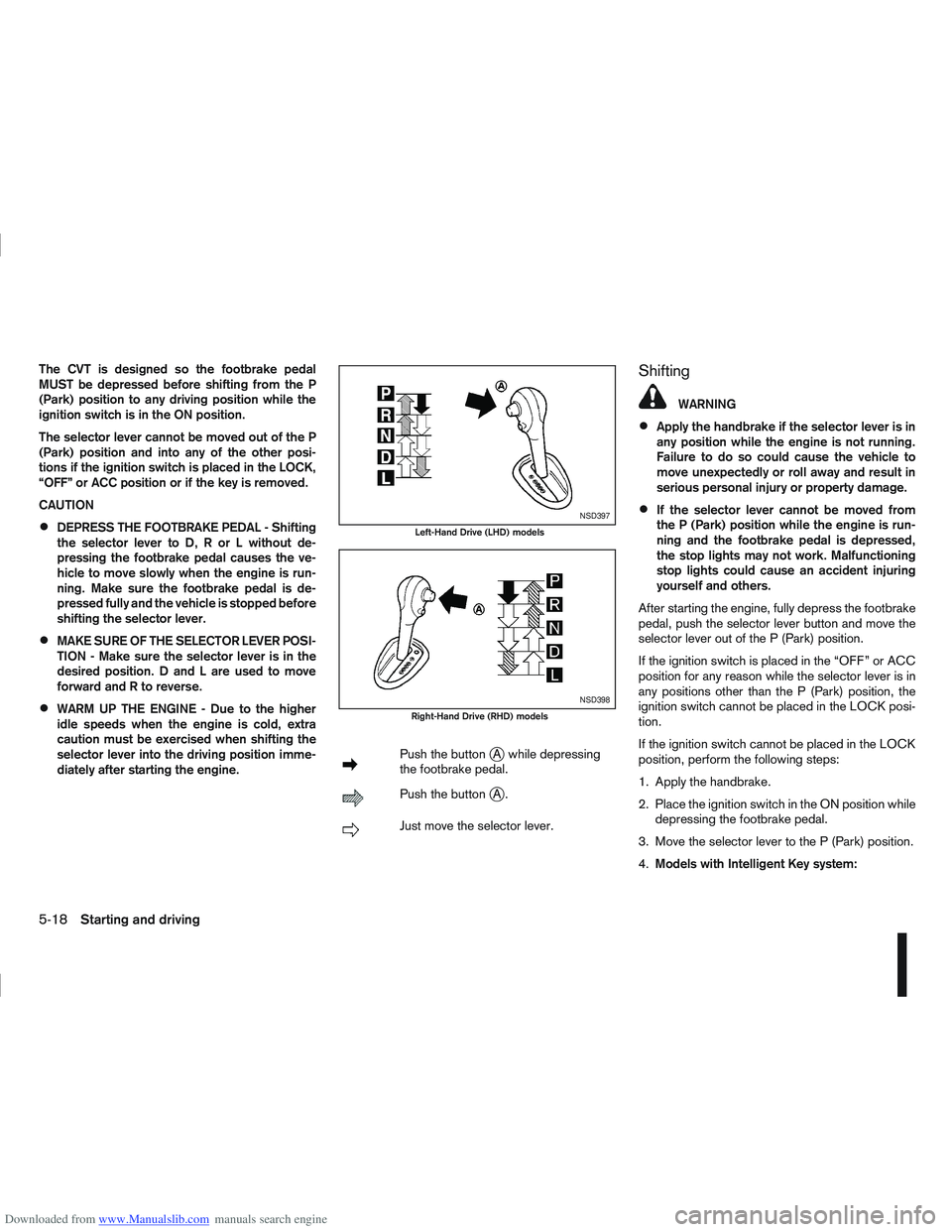
mPush the buttonjA while depressing
the footbrake pedal.
mPush the buttonjA.
mJust move the selector lever.
Shifting
WARNING
Apply the handbrake if the selector lever is in
any position while the engine is not running.
Failure to do so could cause the vehicle to
move unexpectedly or roll away and result in
serious personal injury or property damage.
If the selector lever cannot be moved from
the P (Park) position while the engine is run-
ning and the footbrake pedal is depressed,
the stop lights may not work. Malfunctioning
stop lights could cause an accident injuring
yourself and others.
After starting the engine, fully depress the footbrake
pedal, push the selector lever button and move the
selector lever out of the P (Park) position.
If the ignition switch is placed in the “OFF” or ACC
position for any reason while the selector lever is in
any positions other than the P (Park) position, the
ignition switch cannot be placed in the LOCK posi-
tion.
If the ignition switch cannot be placed in the LOCK
position, perform the following steps:
1. Apply the handbrake.
2. Place the ignition switch in the ON position while depressing the footbrake pedal.
3. Move the selector lever to the P (Park) position.
4. Models with Intelligent Key system:NSD397
Left-Hand Drive (LHD) models
NSD398
Right-Hand Drive (RHD) models
5-18Starting and driving