ECO mode NISSAN QASHQAI 2016 Owner´s Manual
[x] Cancel search | Manufacturer: NISSAN, Model Year: 2016, Model line: QASHQAI, Model: NISSAN QASHQAI 2016Pages: 338, PDF Size: 4.87 MB
Page 12 of 338
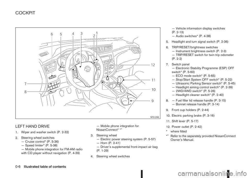
LEFT HAND DRIVE
1.Wiper and washer switch (P. 2-32)
2.Steering wheel switches
— Cruise control* (P. 5-36)
— Speed limiter* (P. 5-38)
— Mobile phone integration for FM-AM radio
with CD player without navigation (P. 4-39)— Mobile phone integration for
NissanConnect* *1
3.Steering wheel
— Electric power steering system (P. 5-57)
— Horn (P. 2-41)
— Driver’s supplemental front-impact air bag
(P. 1-29)
4.Steering wheel switches— Vehicle information display switches
(P. 2-13)
— Audio switches* (P. 4-38)
5.Headlight and turn signal switch (P. 2-36)
6.TRIP/RESET/brightness switches
— Instrument brightness switch (P. 2-3)
— TRIP/RESET switch for twin trip odometer
(P. 2-2)
7.Switch panel
— Electronic Stability Programme (ESP) OFF
switch* (P. 5-60)
— ECO mode switch* (P. 5-65)
— Stop/Start System OFF switch* (P. 5-22)
— Ultrasonic Parking Sensor switch* (P. 5-45)
— Headlight aiming control switch* (P. 2-39)
— 2WD/4WD switch* (P. 5-26)
— Headlight cleaner switch* (P. 2-40)
8.— Fuel filler lid release handle (P. 3-15)
— Bonnet release handle (P. 3-14)
9.Front cup holders (P. 2-44)
10.Electric parking brake (P. 3-16)
11.Shift lever (P. 5-17)
12.Power outlet (P. 2-42)
* where fitted
*1Refer to the separately provided NissanConnect
Owner’s Manual.
NPA1268
COCKPIT
0-6Illustrated table of contents
Page 13 of 338
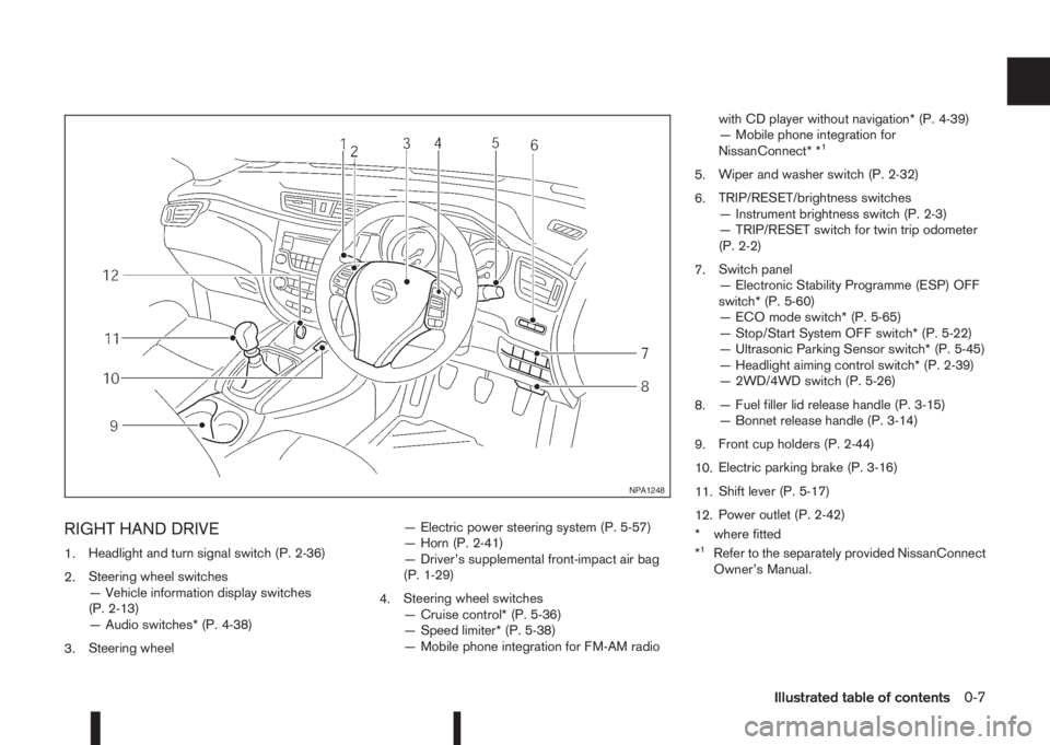
RIGHT HAND DRIVE
1.Headlight and turn signal switch (P. 2-36)
2.Steering wheel switches
— Vehicle information display switches
(P. 2-13)
— Audio switches* (P. 4-38)
3.Steering wheel— Electric power steering system (P. 5-57)
— Horn (P. 2-41)
— Driver’s supplemental front-impact air bag
(P. 1-29)
4.Steering wheel switches
— Cruise control* (P. 5-36)
— Speed limiter* (P. 5-38)
— Mobile phone integration for FM-AM radiowith CD player without navigation* (P. 4-39)
— Mobile phone integration for
NissanConnect* *
1
5.Wiper and washer switch (P. 2-32)
6.TRIP/RESET/brightness switches
— Instrument brightness switch (P. 2-3)
— TRIP/RESET switch for twin trip odometer
(P. 2-2)
7.Switch panel
— Electronic Stability Programme (ESP) OFF
switch* (P. 5-60)
— ECO mode switch* (P. 5-65)
— Stop/Start System OFF switch* (P. 5-22)
— Ultrasonic Parking Sensor switch* (P. 5-45)
— Headlight aiming control switch* (P. 2-39)
— 2WD/4WD switch (P. 5-26)
8.— Fuel filler lid release handle (P. 3-15)
— Bonnet release handle (P. 3-14)
9.Front cup holders (P. 2-44)
10.Electric parking brake (P. 3-16)
11.Shift lever (P. 5-17)
12.Power outlet (P. 2-42)
* where fitted
*
1Refer to the separately provided NissanConnect
Owner’s Manual.
NPA1248
Illustrated table of contents0-7
Page 47 of 338
5. Test the child restraint before you place the child
in itj5 . Push the child restraint from side to side
and tug it forward to make sure that it is held
securely in place.
6. Check to make sure that the child restraint is
properly secured prior to each use. If the child
restraint is loose, repeat steps 3 through 5.
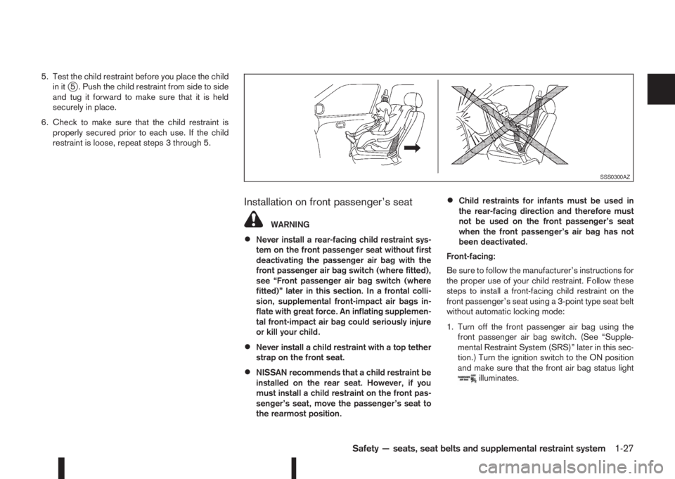
Installation on front passenger’s seat
WARNING
•Never install a rear-facing child restraint sys-
tem on the front passenger seat without first
deactivating the passenger air bag with the
front passenger air bag switch (where fitted),
see “Front passenger air bag switch (where
fitted)” later in this section. In a frontal colli-
sion, supplemental front-impact air bags in-
flate with great force. An inflating supplemen-
tal front-impact air bag could seriously injure
or kill your child.
•Never install a child restraint with a top tether
strap on the front seat.
•NISSAN recommends that a child restraint be
installed on the rear seat. However, if you
must install a child restraint on the front pas-
senger’s seat, move the passenger’s seat to
the rearmost position.
•Child restraints for infants must be used in
the rear-facing direction and therefore must
not be used on the front passenger’s seat
when the front passenger’s air bag has not
been deactivated.
Front-facing:
Be sure to follow the manufacturer’s instructions for
the proper use of your child restraint. Follow these
steps to install a front-facing child restraint on the
front passenger’s seat using a 3-point type seat belt
without automatic locking mode:
1. Turn off the front passenger air bag using the
front passenger air bag switch. (See “Supple-
mental Restraint System (SRS)” later in this sec-
tion.) Turn the ignition switch to the ON position
and make sure that the front air bag status light
illuminates.
SSS0300AZ
Safety — seats, seat belts and supplemental restraint system1-27
Page 60 of 338
NOTE
For an overview see “Meters and gauges” in the
“0. Illustrated table of contents” section and see
“Instrument and control layout” in the “0. Illus-
trated table of contents” section.
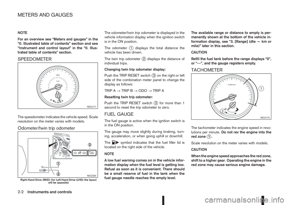
SPEEDOMETER
The speedometer indicates the vehicle speed. Scale
resolution on the meter varies with models.
Odometer/twin trip odometer
The odometer/twin trip odometer is displayed in the
vehicle information display when the ignition switch
is in the ON position.
The odometer
j1 displays the total distance the
vehicle has been driven.
The twin trip odometer
j2 displays the distance of
individual trips.
Changing twin trip odometer display:
Push the TRIP RESET switch
j3 on the right or left
side of the combination meter panel to change the
display as follows:
TRIP A→TRIP B→ODO→TRIP A
Resetting twin trip odometer:
Push the TRIP RESET switch
j3 for more than 1
second to reset the trip odometer to zero.
FUEL GAUGE
The fuel gauge is active when the ignition switch is
in the ON position.
The gauge may move slightly during braking, turn-
ing, acceleration, or when going uphill or downhill.
The
csymbol indicates that the fuel filler lid is
located on the right side of the vehicle.
NOTE
A low fuel warning comes on in the vehicle infor-
mation display when the fuel level is getting low.
Refuel as soon as it is convenient. There should
be a small reserve of fuel in the tank when the
fuel gauge needle reaches the empty level.The available range or distance to empty is per-
manently shown at the bottom of the vehicle in-
formation display, see “3. [Range] (dte — km or
mile)” later in this section.
CAUTION
Refill the fuel tank before the range displays “0”,
or “---”, and the gauge registers empty.
TACHOMETER
The tachometer indicates the engine speed in revo-
lutions per minute.Do not rev the engine into the
red zone
j1.
Scale resolution on the meter varies with models.
CAUTION
When the engine speed approaches the red zone,
shift to a higher gear. Operating the engine in the
red zone may cause serious engine damage.
NIC2171
NIC2334Right-Hand Drive (RHD) (for Left-Hand Drive (LHD) the layout
will be opposite)
NIC2172
METERS AND GAUGES
2-2Instruments and controls
Page 61 of 338
ENGINE COOLANT TEMPERATURE
GAUGE
The gauge indicates the engine coolant tempera-
ture. The engine coolant temperature should remain
within the normal range
j2.
The engine coolant temperature varies with the out-
side air temperature and driving conditions.
CAUTION
If the gauge exceeds the normal range, stop as
soon as it is safely possible. If the engine has
overheated, continued operation of the vehicle
may seriously damage the engine. See “Engine
overheat” in the “6. In case of emergency” sec-
tion for immediate action.
WARNING
Allow the engine to cool down before removing
the radiator cap to avoid the danger of being
scalded.
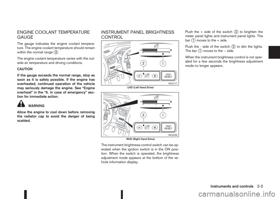
INSTRUMENT PANEL BRIGHTNESS
CONTROL
The instrument brightness control switch can be op-
erated when the ignition switch is in the ON posi-
tion. When the switch is operated, the brightness
adjustment mode appears at the bottom of the ve-
hicle information display.Push the + side of the switch
j2 to brighten the
meter panel lights and instrument panel lights. The
bar
j1 moves to the + side.
Push the - side of the switch
j2 to dim the lights.
The barj1 moves to the − side.
When the instrument brightness control is not oper-
ated for a few seconds the brightness adjustment
mode no longer appears.
NIC2117LHD (Left Hand Drive)
NIC2226RHD (Right Hand Drive)
Instruments and controls2-3
Page 68 of 338
accident. To help avoid injury to yourself or oth-
ers, have your vehicle checked by a NISSAN
dealer or qualified workshop as soon as pos-
sible.
When the ignition switch is in the ON or START
position, the Supplemental Restraint System (SRS)
air bag warning light illuminates for approximately 7
seconds and then turns off this indicates the system
is operational.
If any of the following conditions occur, the air bag
systems and pre-tensioner systems need servicing
and the vehicle must be taken to a NISSAN dealer
or qualified workshop:
•The supplemental air bag warning light remains
on after approximately 7 seconds.
•The supplemental air bag warning light flashes
intermittently.
•The supplemental air bag warning light does not
come on at all.
Unless checked and repaired, the SRS air bag sys-
tem and/or the pre-tensioner seat belt system may
not function properly.
For additional details see “SRS air bag warning
light” in the “1. Safety — Seats, Seat belts and
Supplemental Restraint System” section.
Water in fuel filter warning light
(where fitted)
If the warning light remains on or flashes irregularly
while the engine is running, there may be water in
the fuel filter. Should this happen, contact a NISSAN
dealer or qualified workshop.
CAUTION
Failure to drain the water from the fuel filter can
cause serious damage to the engine. Contact a
NISSAN dealer or qualified workshop as soon as
possible.
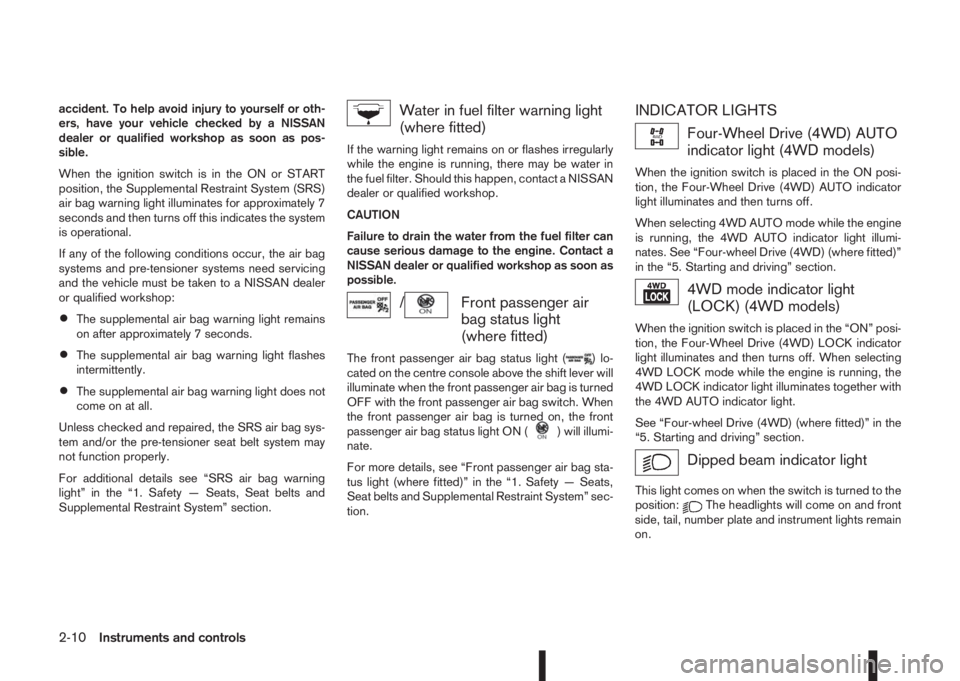
/Front passenger air
bag status light
(where fitted)
The front passenger air bag status light () lo-
cated on the centre console above the shift lever will
illuminate when the front passenger air bag is turned
OFF with the front passenger air bag switch. When
the front passenger air bag is turned on, the front
passenger air bag status light ON (
) will illumi-
nate.
For more details, see “Front passenger air bag sta-
tus light (where fitted)” in the “1. Safety — Seats,
Seat belts and Supplemental Restraint System” sec-
tion.
INDICATOR LIGHTS
Four-Wheel Drive (4WD) AUTO
indicator light (4WD models)
When the ignition switch is placed in the ON posi-
tion, the Four-Wheel Drive (4WD) AUTO indicator
light illuminates and then turns off.
When selecting 4WD AUTO mode while the engine
is running, the 4WD AUTO indicator light illumi-
nates. See “Four-wheel Drive (4WD) (where fitted)”
in the “5. Starting and driving” section.
4WD mode indicator light
(LOCK) (4WD models)
When the ignition switch is placed in the “ON” posi-
tion, the Four-Wheel Drive (4WD) LOCK indicator
light illuminates and then turns off. When selecting
4WD LOCK mode while the engine is running, the
4WD LOCK indicator light illuminates together with
the 4WD AUTO indicator light.
See “Four-wheel Drive (4WD) (where fitted)” in the
“5. Starting and driving” section.
Dipped beam indicator light
This light comes on when the switch is turned to the
position:The headlights will come on and front
side, tail, number plate and instrument lights remain
on.
2-10Instruments and controls
Page 69 of 338
Door lock indicator light
(where fitted)
The door lock indicator light located on the instru-
ment panel illuminates when all the doors are locked
while the ignition switch is in the ON position.
•When the doors are locked with the power door
lock switch, the door lock indicator light will illu-
minate for 30 minutes.
•When the doors are locked by pushing the
LOCK button on the Intelligent Key or any re-
quest switch (where fitted), the door lock indica-
tor light will illuminate for 1 minute.
•The door lock indicator light turns off when any
door is unlocked.
For locking or unlocking doors, see “Door locks” in
the “3. Pre-driving checks and adjustments” sec-
tion.
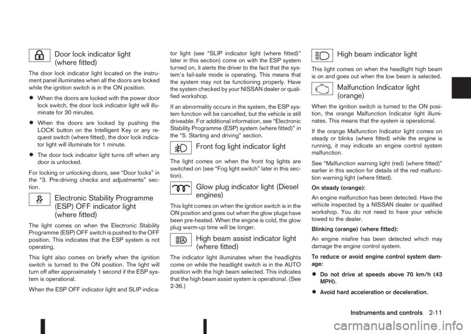
Electronic Stability Programme
(ESP) OFF indicator light
(where fitted)
The light comes on when the Electronic Stability
Programme (ESP) OFF switch is pushed to the OFF
position. This indicates that the ESP system is not
operating.
This light also comes on briefly when the ignition
switch is turned to the ON position. The light will
turn off after approximately 1 second if the ESP sys-
tem is operational.
When the ESP OFF indicator light and SLIP indica-tor light (see “SLIP indicator light (where fitted)”
later in this section) come on with the ESP system
turned on, it alerts the driver to the fact that the sys-
tem’s fail-safe mode is operating. This means that
the system may not be functioning properly. Have
the system checked by your NISSAN dealer or quali-
fied workshop.
If an abnormality occurs in the system, the ESP sys-
tem function will be cancelled, but the vehicle is still
driveable. For additional information, see “Electronic
Stability Programme (ESP) system (where fitted)” in
the “5. Starting and driving” section.
Front fog light indicator light
The light comes on when the front fog lights are
switched on (see “Fog light switch” later in this sec-
tion).
Glow plug indicator light (Diesel
engines)
This light comes on when the ignition switch is in the
ON position and goes out when the glow plugs have
been pre-heated. When the engine is cold, the glow
plug warm-up time will be longer.
High beam assist indicator light
(where fitted)
The indicator light illuminates when the headlights
come on while the headlight switch is in the AUTO
position with the high beam selected. This indicates
that the high beam assist system is operational. (See
2-36.)
High beam indicator light
This light comes on when the headlight high beam
is on and goes out when the low beam is selected.
Malfunction Indicator light
(orange)
When the ignition switch is turned to the ON posi-
tion, the orange Malfunction Indicator light illumi-
nates. This means that the system is operational.
If the orange Malfunction Indicator light comes on
steady or blinks (where fitted) while the engine is
running, it may indicate an engine control system
malfunction.
See “Malfunction warning light (red) (where fitted)”
earlier in this section for details of the red malfunc-
tion warning light (where fitted).
On steady (orange):
An engine malfunction has been detected. Have the
vehicle inspected by a NISSAN dealer or qualified
workshop. You do not need to have your vehicle
towed to the dealer.
Blinking (orange) (where fitted):
An engine misfire has been detected which may
damage the engine control system.
To reduce or avoid engine control system dam-
age:
•Do not drive at speeds above 70 km/h (43
MPH).
•Avoid hard acceleration or deceleration.
Instruments and controls2-11
Page 70 of 338
•Avoid steep uphill grades.
•If possible, reduce the load being carried or
towed.
The Malfunction Indicator light may stop blinking
and come on steady.
Have the vehicle inspected by a NISSAN dealer or
qualified workshop. You do not need to have your
vehicle towed to the dealer.
CAUTION
Continued vehicle operation without having the
engine control system checked and repaired as
necessary could lead to poor driveability,
reduced fuel economy and possible damage to
the engine control system, which may affect your
warranty coverage.
Rear fog light indicator light
(where fitted)
The light comes on when the rear fog light is
switched on (see “Rear fog light (where fitted)” later
in this section).
Side light and headlight indicator
light
This light comes on when the side light or headlight
position is selected, see “Headlight and turn signal
switch” later in this section for further details.
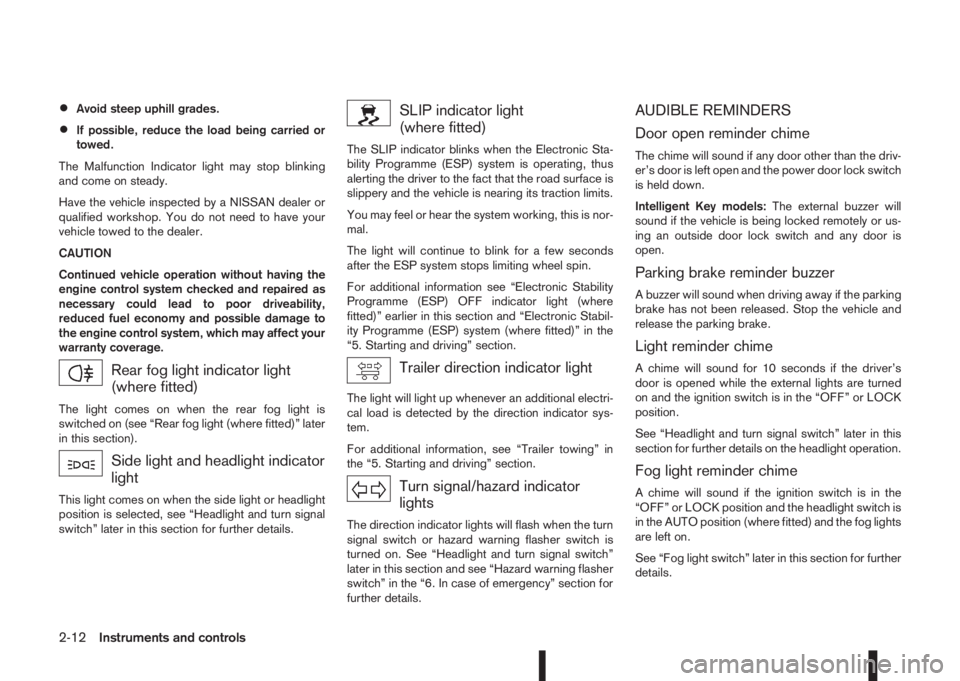
SLIP indicator light
(where fitted)
The SLIP indicator blinks when the Electronic Sta-
bility Programme (ESP) system is operating, thus
alerting the driver to the fact that the road surface is
slippery and the vehicle is nearing its traction limits.
You may feel or hear the system working, this is nor-
mal.
The light will continue to blink for a few seconds
after the ESP system stops limiting wheel spin.
For additional information see “Electronic Stability
Programme (ESP) OFF indicator light (where
fitted)” earlier in this section and “Electronic Stabil-
ity Programme (ESP) system (where fitted)” in the
“5. Starting and driving” section.
Trailer direction indicator light
The light will light up whenever an additional electri-
cal load is detected by the direction indicator sys-
tem.
For additional information, see “Trailer towing” in
the “5. Starting and driving” section.
Turn signal/hazard indicator
lights
The direction indicator lights will flash when the turn
signal switch or hazard warning flasher switch is
turned on. See “Headlight and turn signal switch”
later in this section and see “Hazard warning flasher
switch” in the “6. In case of emergency” section for
further details.
AUDIBLE REMINDERS
Door open reminder chime
The chime will sound if any door other than the driv-
er’s door is left open and the power door lock switch
is held down.
Intelligent Key models:The external buzzer will
sound if the vehicle is being locked remotely or us-
ing an outside door lock switch and any door is
open.
Parking brake reminder buzzer
A buzzer will sound when driving away if the parking
brake has not been released. Stop the vehicle and
release the parking brake.
Light reminder chime
A chime will sound for 10 seconds if the driver’s
door is opened while the external lights are turned
on and the ignition switch is in the “OFF” or LOCK
position.
See “Headlight and turn signal switch” later in this
section for further details on the headlight operation.
Fog light reminder chime
A chime will sound if the ignition switch is in the
“OFF” or LOCK position and the headlight switch is
in the AUTO position (where fitted) and the fog lights
are left on.
See “Fog light switch” later in this section for further
details.
2-12Instruments and controls
Page 71 of 338
Seat belt reminder chime
A chime will sound for approximately 90 seconds if
the vehicle’s speed exceeds 15 km/h (9 MPH) and
the driver’s seat belt or front passenger’s seat belt,
if occupied (where fitted) is not securely fastened.
See “Seat belt warnings” in the “1. Safety — Seats,
Seat belts and Supplemental Restraint System” sec-
tion.
Key reminder buzzer (Intelligent Key
models)
The external buzzer will beep 3 times if:
•The Intelligent Key is removed from the vehicle
while the ignition is not in the LOCK position.
•The vehicle is being locked remotely or using an
outside door lock switch and the Intelligent Key
has been left inside the vehicle.
Park reminder chime (where fitted)
A chime will sound if the ignition switch is placed in
the LOCK position and the shift lever is not in the P
(Park) position.
Stop/Start System reminder buzzer
(where fitted)
The engine will shift to the normal stopped state if
any of the following operations is made during Stop/
Start System activation, and the Stop/Start System
buzzer will sound if:
– The driver’s seat belt is unfastened and the driv-
er’s door is open (MT models)– The vehicle engine bonnet is open.
When any of the above conditions continues for
over 3 minutes the Stop/Start System buzzer will
sound in 5-minute intervals as a reminder to prevent
the possibility of a dead battery. Use the ignition
switch to turn off the engine.
Close the bonnet or the driver’s door, or fasten the
seat belt then restart the engine using the ignition
switch.
For more information, see “[Stop/Start]” in the “5. In-
struments and controls” section and “Stop/Start
System (where fitted)” in the “5. Starting and driving”
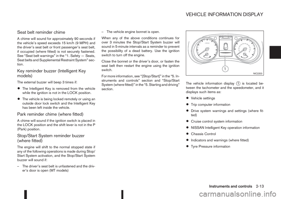
section.The vehicle information display
j1 is located be-
tween the tachometer and the speedometer, and it
displays such items as:
•Vehicle settings
•Trip computer information
•Drive system warnings and settings (where fit-
ted)
•Cruise control system information
•NISSAN Intelligent Key operation information
•Chassis Control
•Indicators and warnings (where fitted)
•Tyre Pressure information
NIC2203
VEHICLE INFORMATION DISPLAY
Instruments and controls2-13
Page 72 of 338
HOW TO USE THE VEHICLE
INFORMATION DISPLAY
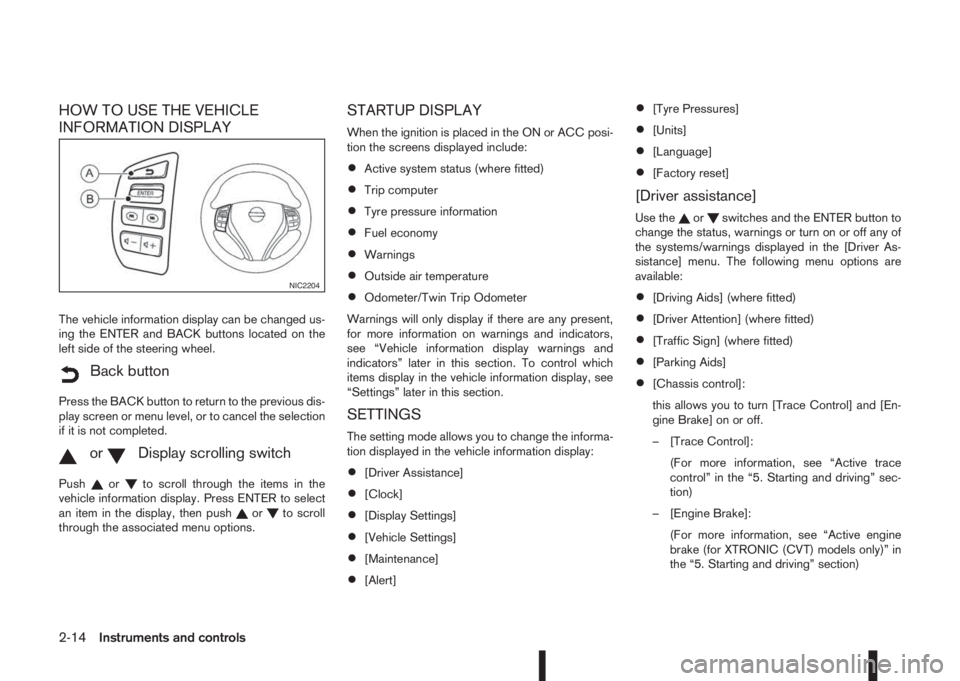
The vehicle information display can be changed us-
ing the ENTER and BACK buttons located on the
left side of the steering wheel.
mBack button
Press the BACK button to return to the previous dis-
play screen or menu level, or to cancel the selection
if it is not completed.
mormDisplay scrolling switch
Pushorto scroll through the items in the
vehicle information display. Press ENTER to select
an item in the display, then push
orto scroll
through the associated menu options.
STARTUP DISPLAY
When the ignition is placed in the ON or ACC posi-
tion the screens displayed include:
•Active system status (where fitted)
•Trip computer
•Tyre pressure information
•Fuel economy
•Warnings
•Outside air temperature
•Odometer/Twin Trip Odometer
Warnings will only display if there are any present,
for more information on warnings and indicators,
see “Vehicle information display warnings and
indicators” later in this section. To control which
items display in the vehicle information display, see
“Settings” later in this section.
SETTINGS
The setting mode allows you to change the informa-
tion displayed in the vehicle information display:
•[Driver Assistance]
•[Clock]
•[Display Settings]
•[Vehicle Settings]
•[Maintenance]
•[Alert]
•[Tyre Pressures]
•[Units]
•[Language]
•[Factory reset]
[Driver assistance]
Use theorswitches and the ENTER button to
change the status, warnings or turn on or off any of
the systems/warnings displayed in the [Driver As-
sistance] menu. The following menu options are
available:
•[Driving Aids] (where fitted)
•[Driver Attention] (where fitted)
•[Traffic Sign] (where fitted)
•[Parking Aids]
•[Chassis control]:
this allows you to turn [Trace Control] and [En-
gine Brake] on or off.
– [Trace Control]:
(For more information, see “Active trace
control” in the “5. Starting and driving” sec-
tion)
– [Engine Brake]:
(For more information, see “Active engine
brake (for XTRONIC (CVT) models only)” in
the “5. Starting and driving” section)
NIC2204
2-14Instruments and controls