open bonnet NISSAN QASHQAI 2016 Owner´s Manual
[x] Cancel search | Manufacturer: NISSAN, Model Year: 2016, Model line: QASHQAI, Model: NISSAN QASHQAI 2016Pages: 338, PDF Size: 4.87 MB
Page 71 of 338
Seat belt reminder chime
A chime will sound for approximately 90 seconds if
the vehicle’s speed exceeds 15 km/h (9 MPH) and
the driver’s seat belt or front passenger’s seat belt,
if occupied (where fitted) is not securely fastened.
See “Seat belt warnings” in the “1. Safety — Seats,
Seat belts and Supplemental Restraint System” sec-
tion.
Key reminder buzzer (Intelligent Key
models)
The external buzzer will beep 3 times if:
•The Intelligent Key is removed from the vehicle
while the ignition is not in the LOCK position.
•The vehicle is being locked remotely or using an
outside door lock switch and the Intelligent Key
has been left inside the vehicle.
Park reminder chime (where fitted)
A chime will sound if the ignition switch is placed in
the LOCK position and the shift lever is not in the P
(Park) position.
Stop/Start System reminder buzzer
(where fitted)
The engine will shift to the normal stopped state if
any of the following operations is made during Stop/
Start System activation, and the Stop/Start System
buzzer will sound if:
– The driver’s seat belt is unfastened and the driv-
er’s door is open (MT models)– The vehicle engine bonnet is open.
When any of the above conditions continues for
over 3 minutes the Stop/Start System buzzer will
sound in 5-minute intervals as a reminder to prevent
the possibility of a dead battery. Use the ignition
switch to turn off the engine.
Close the bonnet or the driver’s door, or fasten the
seat belt then restart the engine using the ignition
switch.
For more information, see “[Stop/Start]” in the “5. In-
struments and controls” section and “Stop/Start
System (where fitted)” in the “5. Starting and driving”
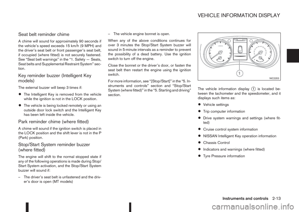
section.The vehicle information display
j1 is located be-
tween the tachometer and the speedometer, and it
displays such items as:
•Vehicle settings
•Trip computer information
•Drive system warnings and settings (where fit-
ted)
•Cruise control system information
•NISSAN Intelligent Key operation information
•Chassis Control
•Indicators and warnings (where fitted)
•Tyre Pressure information
NIC2203
VEHICLE INFORMATION DISPLAY
Instruments and controls2-13
Page 90 of 338
WARNING
In freezing temperatures the washer fluid may
freeze on the windscreen and obscure your vi-
sion. Warm the windscreen with the defogger be-
fore you wash it.
CAUTION
•Do not open/release the bonnet when the
front wiper arms are raised from their original
position.
•Do not operate the washer continuously for
more than 15 seconds.
•Do not operate the washer if the reservoir
tank is empty or frozen.
WINDSCREEN
The windscreen wiper and washer can be operated
when the ignition switch is in the ON position.
Wiper operation
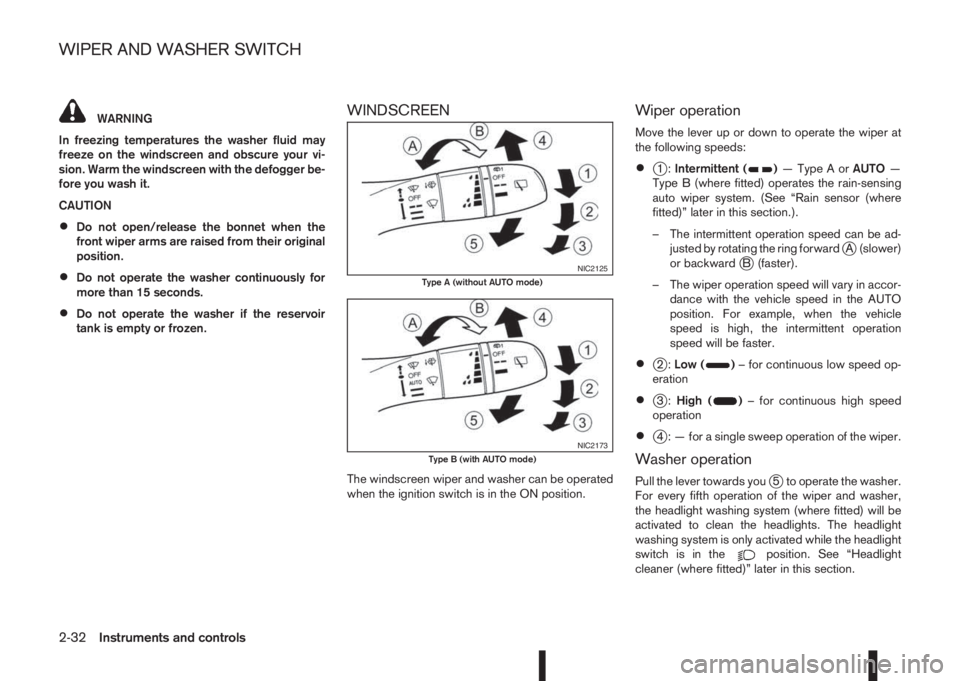
Move the lever up or down to operate the wiper at
the following speeds:
•j1:Intermittent ()—TypeAorAUTO—
Type B (where fitted) operates the rain-sensing
auto wiper system. (See “Rain sensor (where
fitted)” later in this section.).
– The intermittent operation speed can be ad-
justed by rotating the ring forward
jA (slower)
or backwardjB (faster).
– The wiper operation speed will vary in accor-
dance with the vehicle speed in the AUTO
position. For example, when the vehicle
speed is high, the intermittent operation
speed will be faster.
•j2:Low ()– for continuous low speed op-
eration
•j3:High ()– for continuous high speed
operation
•j4 : — for a single sweep operation of the wiper.
Washer operation
Pull the lever towards youj5 to operate the washer.
For every fifth operation of the wiper and washer,
the headlight washing system (where fitted) will be
activated to clean the headlights. The headlight
washing system is only activated while the headlight
switch is in the
position. See “Headlight
cleaner (where fitted)” later in this section.
NIC2125Type A (without AUTO mode)
NIC2173Type B (with AUTO mode)
WIPER AND WASHER SWITCH
2-32Instruments and controls
Page 111 of 338
3Pre-driving checks and adjustmentsPre-driving checks and adjustments
Keys ........................................................................ 3-2
NISSAN Anti-Theft System (NATS)* key ............. 3-2
Intelligent Key (where fitted)................................ 3-2
Key number ........................................................ 3-3
New keys ........................................................... 3-3
Emergency/mechanical key (Intelligent Key
models) .............................................................. 3-3
Integrated keyfob/remote control system .................. 3-4
Switching from Convenience mode to
Anti-hijack mode (where fitted) ............................ 3-5
Using the remote keyless entry system ................ 3-5
Locking the doors ............................................... 3-5
Unlocking the doors ............................................ 3-5
Keyfob operation failure ...................................... 3-5
Intelligent Key system (where fitted) ......................... 3-6
Intelligent Key operating range ............................ 3-6
Using Intelligent Key system................................ 3-6
Locking/unlocking .............................................. 3-7
Starting the engine with the Intelligent Key .......... 3-8
Door locks ............................................................... 3-8
Super Lock system (RHD models) ...................... 3-8
Locking/unlocking with the key (vehicle dead
battery) ............................................................... 3-9Inside door handle .............................................. 3-10
Power door lock switch ...................................... 3-10
Child safety lock — rear doors............................ 3-11
Back door lock ................................................... 3-11
Security system ....................................................... 3-12
Alarm system (where fitted) ................................ 3-12
NISSAN Anti-Theft System (NATS)..................... 3-13
Bonnet release ........................................................ 3-14
Fuel filler lid ............................................................. 3-15
Fuel filler lid opener lever .................................... 3-15
Fuel filler cap ...................................................... 3-15
Parking brake switch ............................................... 3-16
Driving away when towing a trailer ...................... 3-17
Steering wheel......................................................... 3-18
Sun visors ............................................................... 3-18
Mirrors..................................................................... 3-18
Inside rear-view mirror ........................................ 3-18
Automatic anti-dazzling inside mirror (where
fitted).................................................................. 3-19
Outside rear-view mirrors.................................... 3-19
Vanity mirror ....................................................... 3-20
Page 122 of 338
Vehicle dead battery – Back door lock
release lever (where fitted)
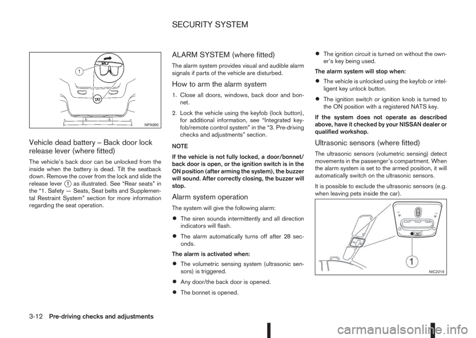
The vehicle’s back door can be unlocked from the
inside when the battery is dead. Tilt the seatback
down. Remove the cover from the lock and slide the
release lever
j1 as illustrated. See “Rear seats” in
the “1. Safety — Seats, Seat belts and Supplemen-
tal Restraint System” section for more information
regarding the seat operation.
ALARM SYSTEM (where fitted)
The alarm system provides visual and audible alarm
signals if parts of the vehicle are disturbed.
How to arm the alarm system
1. Close all doors, windows, back door and bon-
net.
2. Lock the vehicle using the keyfob (lock button),
for additional information, see “Integrated key-
fob/remote control system” in the “3. Pre-driving
checks and adjustments” section.
NOTE
If the vehicle is not fully locked, a door/bonnet/
back door is open, or the ignition switch is in the
ON position (after arming the system), the buzzer
will sound. After correctly closing, the buzzer will
stop.
Alarm system operation
The system will give the following alarm:
•The siren sounds intermittently and all direction
indicators will flash.
•The alarm automatically turns off after 28 sec-
onds.
The alarm is activated when:
•The volumetric sensing system (ultrasonic sen-
sors) is triggered.
•Any door/the back door is opened.
•The bonnet is opened.
•The ignition circuit is turned on without the own-
er’s key being used.
The alarm system will stop when:
•The vehicle is unlocked using the keyfob or intel-
ligent key unlock button.
•The ignition switch or ignition knob is turned to
the ON position with a registered NATS key.
If the system does not operate as described
above, have it checked by your NISSAN dealer or
qualified workshop.
Ultrasonic sensors (where fitted)
The ultrasonic sensors (volumetric sensing) detect
movements in the passenger’s compartment. When
the alarm system is set to the armed position, it will
automatically switch on the ultrasonic sensors.
It is possible to exclude the ultrasonic sensors (e.g.
when leaving pets inside the car).
NPA990
NIC2219
SECURITY SYSTEM
3-12Pre-driving checks and adjustments
Page 124 of 338
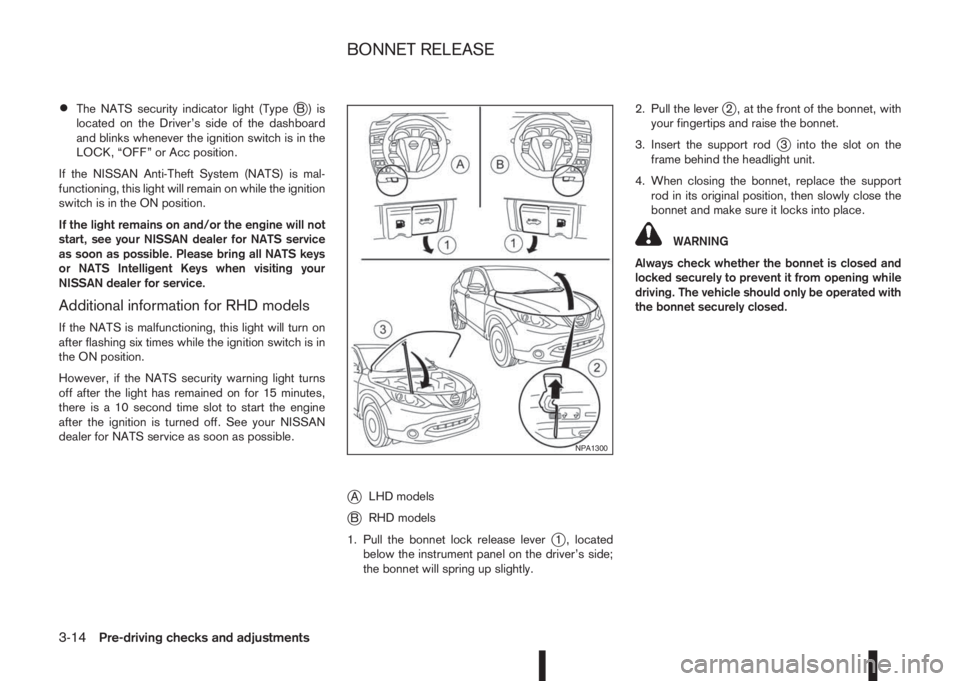
•The NATS security indicator light (TypejB) is
located on the Driver’s side of the dashboard
and blinks whenever the ignition switch is in the
LOCK, “OFF” or Acc position.
If the NISSAN Anti-Theft System (NATS) is mal-
functioning, this light will remain on while the ignition
switch is in the ON position.
If the light remains on and/or the engine will not
start, see your NISSAN dealer for NATS service
as soon as possible. Please bring all NATS keys
or NATS Intelligent Keys when visiting your
NISSAN dealer for service.
Additional information for RHD models
If the NATS is malfunctioning, this light will turn on
after flashing six times while the ignition switch is in
the ON position.
However, if the NATS security warning light turns
off after the light has remained on for 15 minutes,
there is a 10 second time slot to start the engine
after the ignition is turned off. See your NISSAN
dealer for NATS service as soon as possible.
jALHD models
jBRHD models
1. Pull the bonnet lock release lever
j1 , located
below the instrument panel on the driver’s side;
the bonnet will spring up slightly.2. Pull the lever
j2 , at the front of the bonnet, with
your fingertips and raise the bonnet.
3. Insert the support rod
j3 into the slot on the
frame behind the headlight unit.
4. When closing the bonnet, replace the support
rod in its original position, then slowly close the
bonnet and make sure it locks into place.
WARNING
Always check whether the bonnet is closed and
locked securely to prevent it from opening while
driving. The vehicle should only be operated with
the bonnet securely closed.
NPA1300
BONNET RELEASE
3-14Pre-driving checks and adjustments
Page 198 of 338
If the vehicle is driven under extreme conditions,
such as excessive wheel spinning and subse-
quent hard braking, the Fail-safe system may be
activated. This will occur even if all electrical cir-
cuits are functioning properly. In this case, turn
the ignition switch “OFF” and wait for 10 sec-
onds. Then turn the key back to the ON position.
The vehicle should return to its normal operating
condition. If it does not return to its normal oper-
ating condition have your NISSAN dealer or quali-
fied workshop check the transmission and have
the transmission repaired by a NISSAN dealer or
qualified workshop, if necessary.
WARNING
When the fail safe operation occurs, the vehicle
speed may be lower than other traffic, which
could increase the chance of a collision. Be es-
pecially careful when driving. If necessary, drive
to the side of the road at a safe place and away
from traffic, to allow the transmission to return to
normal operation, or have the transmission re-
paired by a NISSAN dealer or qualified workshop,
if necessary.The Stop/Start System is designed to prevent un-
necessary fuel consumption, exhaust emissions,
and noise during a journey:
•When you stop the vehicle with the brake pedal
depressed (XTRONIC transmission) or with the
shift lever in N (Neutral) and clutch pedal re-
leased (MT), the engine is turned off automati-
cally.
•When you release the brake pedal (XTRONIC
transmission) or push the clutch pedal (MT), the
engine is automatically turned on.
CAUTION
At the end of the journey the engine must be
stopped and ignition turned OFF. Lock the ve-
hicle as normal. Turning the ignition OFF will shut
down all electrical systems. Failure to do this may
result in a flat battery.
NORMAL OPERATION
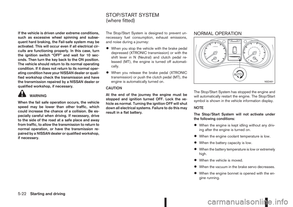
The Stop/Start System has stopped the engine and
will automatically restart the engine. The Stop/Start
symbol is shown in the vehicle information display.
NOTE
The Stop/Start System will not activate under
the following conditions:
•When the engine is kept idling without any driv-
ing after the engine is turned on.
•When the engine coolant temperature is low.
•When the battery capacity is low.
•When the battery temperature is low or extremely
high.
•When the vehicle is moved.
•When the vacuum in the brake servo decreases.
•When the engine bonnet is opened with the en-
gine running.
NSD491
STOP/START SYSTEM
(where fitted)
5-22Starting and driving
Page 199 of 338
•When the engine is turned on with the engine
bonnet open.
•When the driver’s seat belt is not fastened.
•When the driver’s door is open.
•When the steering wheel is operated.
•When the Stop/Start System indicator blinks at
a low speed.
•When the accelerator pedal is depressed
(XTRONIC transmission models).
•When the shift lever is in the R (Reverse) posi-
tion.
•When the fan speed control dial is in any posi-
tion other than “OFF” (0) while the air flow con-
trol dial is in the front defogger position (manual
air conditioner).
•When the front defogger switch is on (automatic
air conditioner).
•When the Stop/Start System OFF switch is
turned on.
•When the electric power steering warning light,
the Anti-lock Braking System (ABS) warning
light, or the Electronic Stability Programme
(ESP) warning light illuminates.
•When the brake pedal is not fully depressed
(XTRONIC transmission models).
•When stopping the vehicle on steep sloping
roads (XTRONIC transmission models).
•When the power consumption is large.
•When the vehicle is travelling at altitudes higher
than 2000 m (6562 ft) (MT models).
•When the vehicle is travelling at altitudes higher
than 1500m (4922 ft) (R9M engine in combina-
tion with XTRONIC transmission models).
NOTE
It may take some time until the Stop/Start Sys-
tem activates under the following conditions:
•When the battery is discharged.
•When the outside temperature is low.
•When the battery is replaced or the battery ter-
minal is disconnected for extended periods and
then reconnected.
NOTE
The engine will not restart even if the brake pedal
is released (XTRONIC transmission ) or clutch
pedal is pressed (MT) while the Stop/Start Sys-
tem is activated under the following condition:
•When the shift lever is in the P (Park) position
(XTRONIC transmission models).
•When the engine bonnet is opened.
•When the driver seat belt is unfastened and the
driver’s door is opened (MT models).
•When the gear shift lever is not in the Neutral
position. (MT models)
NOTE
The engine will restart without releasing thebrake pedal (XTRONIC transmission models) or
without depressing the clutch pedal (MT models)
while the Stop/Start System is activated under
the following conditions:
•When the Stop/Start System OFF switch is
pushed.
•When the fan speed control dial is in any posi-
tion other than “OFF” (0) while the air flow con-
trol dial is in the front defogger position (manual
air conditioner).
•When the front defogger switch is set to “ON”
(automatic air conditioner).
•When the accelerator pedal is depressed.
(XTRONIC transmission models)
•When the steering wheel is operated. (XTRONIC
transmission models)
•When the battery capacity is low.
•When the power consumption is large.
•When the brake pedal is released on sloping
roads and the vehicle is moved.
•When the force to the brake pedal is reduced
while the shift lever is in the D (Drive) or N (Neu-
tral) position. (XTRONIC transmission models)
•When the shift lever is placed in the L (Low), D
(Drive) or R (Reverse) position from the N or P
position. (XTRONIC transmission models)
•When the vacuum of the brake servo is insuffi-
cient as a result of depressing the brake pedal
several times.
Starting and driving5-23
Page 200 of 338
•When the driver’s seat belt is released or the
driver’s door is open. (XTRONIC transmission
models)
Use this system while waiting at stoplight, etc. When
the vehicle is stopped for long periods of time, turn
off the engine.
When the engine bonnet is opened with the Stop/
Start System on, the engine will be in the normal
stopped state with the buzzer sounding. In this case,
restart the engine with the ignition switch.
When the engine is stopped by the Stop/Start Sys-
tem, heating, cooling and dehumidifying functions
will be deactivated. To avoid the air conditioning
functions from being deactivated, turn off the Stop/
Start System by pressing the Stop/Start System
OFF switch.
The Stop/Start System is always engaged at the
start of a journey (once the engine has been started).
The engine is automatically stopped and restarted
during the journey if conditions are suitable
When the engine is stopped the following informa-
tion is displayed for a few seconds.
See “Vehicle information display” in the “2. Instru-
ments and controls” section for information about
the display.
m
NOTE
Automatic engine restart
is possible whenever the
Stop/Start System
symbol is illuminated at
the bottom of the
display.
Whilst the engine remains stopped the vehicle infor-
mation display shows the accumulated quantity (es-
timate) of carbon dioxide exhaust emissions (where
fitted) prevented by the Stop/Start System.
m
The [CO2 Saved] can
be reset in the Settings
menu; see “Vehicle
information display” in
the “2. Instruments and
controls” section.
When automatic restart is not possible the following
information is displayed. The engine must be started
by turning the ignition switch.
m
The message can be
cleared by pressing the
steering wheel
ji button,
restarting the engine, or
turning the ignition OFF.
PRECAUTIONS
The following message is displayed when there may
be something wrong with the Stop/Start System.
You are advised to have the system checked by a
NISSAN dealer or qualified workshop.
m
The message can be
cleared by pressing the
steering wheel ENTER
button
NOTE
The Stop/Start System
symbol at the bottom of
the display flashes whilst
the fault condition
remains.
5-24Starting and driving
Page 247 of 338
In case of a flat tyre, follow the instructions as de-
scribed below:
STOPPING THE VEHICLE
WARNING
•Make sure that the parking brake is securely
applied.
•For Manual Transmission (MT) models: Make
sure the shift lever is in the R (Reverse) posi-
tion.
For XTRONIC models: Make sure that the shift
lever is in the P (Park) position.
•Never change tyres when the vehicle is on a
slope, ice or a slippery area. This is hazard-
ous.
•Never change tyres if oncoming traffic is close
to your vehicle. Wait for professional road as-
sistance.
1. Safely move the vehicle off the road, away from
traffic.
2. Switch on the hazard warning flashers.
3. Park on a level surface.
4. Apply the parking brake.
5. Shift the shift lever (MT models) into the R (Re-
verse) position [XTRONIC models, move the shift
lever to the P (Park) position].
6. Turn off the engine.7. Open the bonnet (for details, see “Bonnet
release” in the “3. Pre-driving checks and
adjustments” section) in order to:
•Warn other traffic.
•Signal to professional road assistance that
you require assistance.
8. Have all passengers exit the vehicle and stand in
a safe place, away from traffic and clear of the
vehicle.
CHANGING FLAT TYRE (Models with
spare wheel, where fitted)
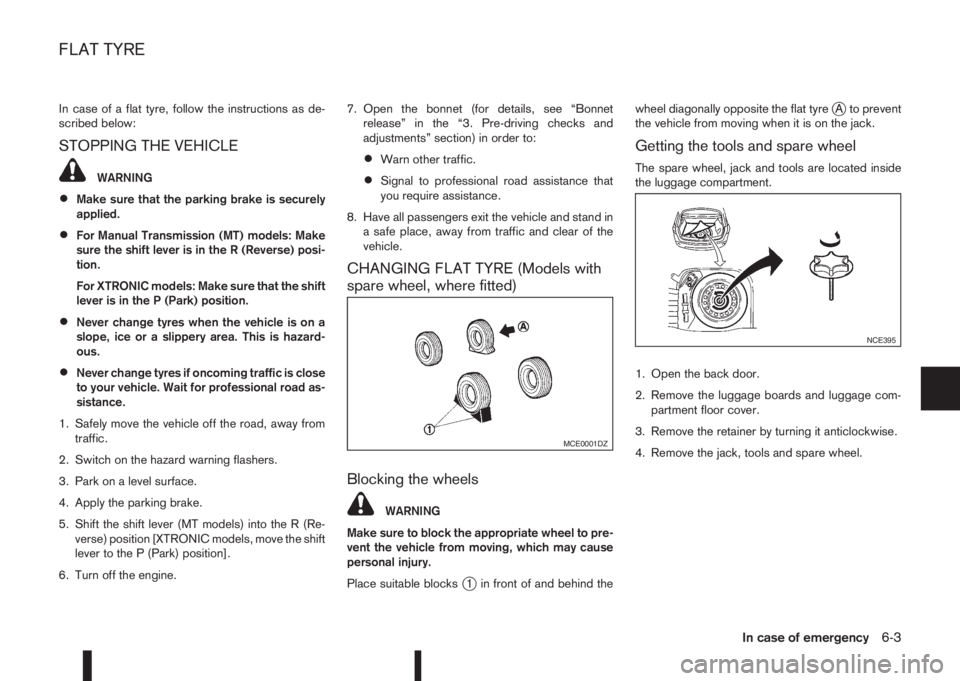
Blocking the wheels
WARNING
Make sure to block the appropriate wheel to pre-
vent the vehicle from moving, which may cause
personal injury.
Place suitable blocks
j1 in front of and behind thewheel diagonally opposite the flat tyre
jA to prevent
the vehicle from moving when it is on the jack.
Getting the tools and spare wheel
The spare wheel, jack and tools are located inside
the luggage compartment.
1. Open the back door.
2. Remove the luggage boards and luggage com-
partment floor cover.
3. Remove the retainer by turning it anticlockwise.
4. Remove the jack, tools and spare wheel.
MCE0001DZ
NCE395
FLAT TYRE
In case of emergency6-3
Page 256 of 338
4. Switch off all unnecessary electrical systems
(headlights, hazard lights etc,).
5. Ensure that the ignition switch of the vehicle be-
ing jump-started is in the LOCK position.
6. Open the bonnet. For details, see “Bonnet
release” in the “3. Pre-driving checks and
adjustments” section.
7. Remove the vent caps (where fitted) on the bat-
tery and cover the battery with an old cloth.
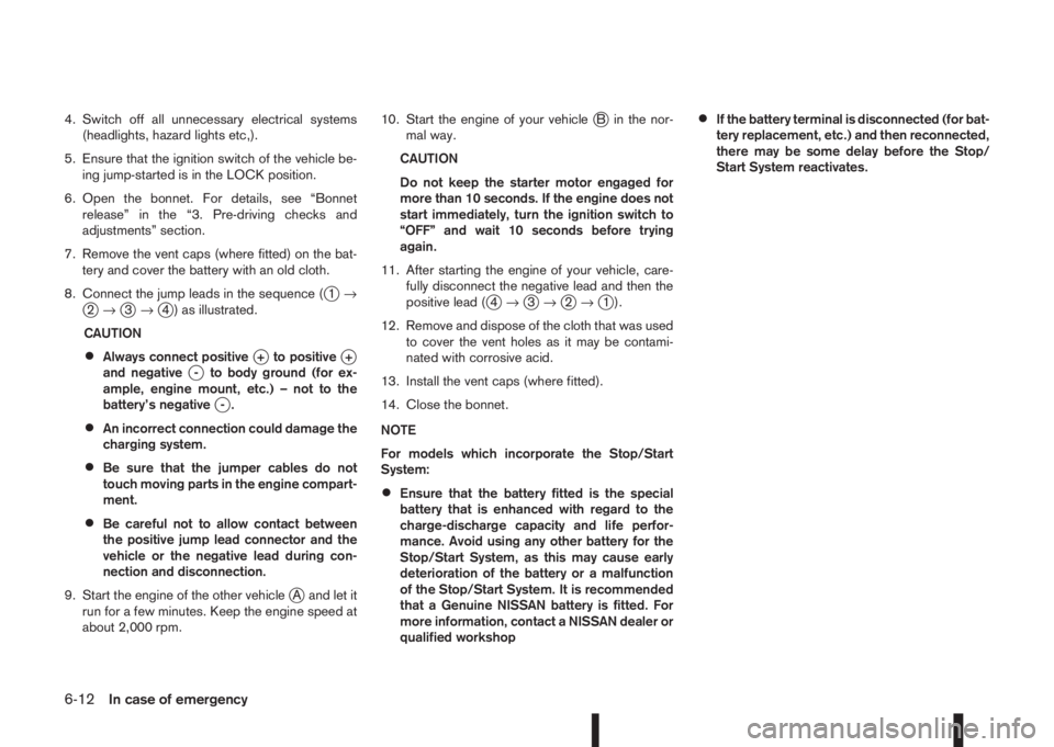
8. Connect the jump leads in the sequence (
j1→j2→j3→j4 ) as illustrated.
CAUTION
•Always connect positivej+ to positivej+
and negativej- to body ground (for ex-
ample, engine mount, etc.) – not to the
battery’s negative
j-.
•An incorrect connection could damage the
charging system.
•Be sure that the jumper cables do not
touch moving parts in the engine compart-
ment.
•Be careful not to allow contact between
the positive jump lead connector and the
vehicle or the negative lead during con-
nection and disconnection.
9. Start the engine of the other vehicle
jA and let it
run for a few minutes. Keep the engine speed at
about 2,000 rpm.10. Start the engine of your vehicle
jB in the nor-
mal way.
CAUTION
Do not keep the starter motor engaged for
more than 10 seconds. If the engine does not
start immediately, turn the ignition switch to
“OFF” and wait 10 seconds before trying
again.
11. After starting the engine of your vehicle, care-
fully disconnect the negative lead and then the
positive lead (
j4→j3→j2→j1).
12. Remove and dispose of the cloth that was used
to cover the vent holes as it may be contami-
nated with corrosive acid.
13. Install the vent caps (where fitted).
14. Close the bonnet.
NOTE
For models which incorporate the Stop/Start
System:
•Ensure that the battery fitted is the special
battery that is enhanced with regard to the
charge-discharge capacity and life perfor-
mance. Avoid using any other battery for the
Stop/Start System, as this may cause early
deterioration of the battery or a malfunction
of the Stop/Start System. It is recommended
that a Genuine NISSAN battery is fitted. For
more information, contact a NISSAN dealer or
qualified workshop
•If the battery terminal is disconnected (for bat-
tery replacement, etc.) and then reconnected,
there may be some delay before the Stop/
Start System reactivates.
6-12In case of emergency