NISSAN QASHQAI 2020 Owner´s Manual
Manufacturer: NISSAN, Model Year: 2020, Model line: QASHQAI, Model: NISSAN QASHQAI 2020Pages: 492, PDF Size: 2.02 MB
Page 191 of 492
.The remote engine startbutton is
not pushed and held within 5 seconds
of pushing the LOCK
button.
. The brake pedal is depressed.
. The doors are not closed and locked.
. The liftgate is open.
. The Key System Error warning mes-
sage remains on in the vehicle infor-
mation display.
. An Intelligent Key is left inside the
vehicle.
. The theft alarm sounds due to illegal
entry into the vehicle.
. Two remote engine starts, or a single
remote engine start with an exten-
sion, have already been used.
. The shift lever is not in the P (Park)
position.
. The remote engine start function has
been switched to the OFF position in
Vehicle Settings of the vehicle infor-
mation display. For additional infor-
mation, see “Vehicle Settings” (P.2-23).
The remote engine start may display a
warning or indicator in the vehicle infor-
mation display. For an explanation of the
warning or indicator, see “Vehicle infor-
mation display warnings and indicators”
(P.2-31).WARNING
. Make sure the hood is completely
closed and latched before driving.
Failure to do so could cause the
hood to fly open and result in an
accident.
. Never open the hood if steam or
smoke is coming from the engine
compartment to avoid injury.
Pre-driving checks and adjustments3-25
HOOD
Page 192 of 492
3-26Pre-driving checks and adjustments
WAD0090X
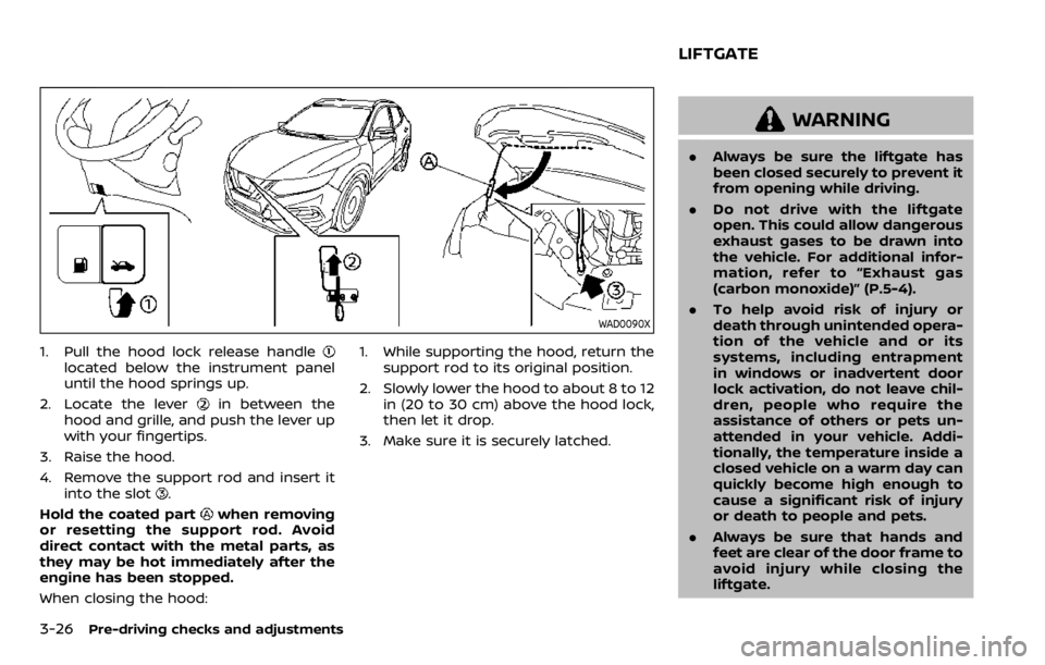
1. Pull the hood lock release handlelocated below the instrument panel
until the hood springs up.
2. Locate the lever
in between the
hood and grille, and push the lever up
with your fingertips.
3. Raise the hood.
4. Remove the support rod and insert it into the slot
.
Hold the coated part
when removing
or resetting the support rod. Avoid
direct contact with the metal parts, as
they may be hot immediately after the
engine has been stopped.
When closing the hood: 1. While supporting the hood, return the
support rod to its original position.
2. Slowly lower the hood to about 8 to 12 in (20 to 30 cm) above the hood lock,
then let it drop.
3. Make sure it is securely latched.
WARNING
. Always be sure the liftgate has
been closed securely to prevent it
from opening while driving.
. Do not drive with the liftgate
open. This could allow dangerous
exhaust gases to be drawn into
the vehicle. For additional infor-
mation, refer to “Exhaust gas
(carbon monoxide)” (P.5-4).
. To help avoid risk of injury or
death through unintended opera-
tion of the vehicle and or its
systems, including entrapment
in windows or inadvertent door
lock activation, do not leave chil-
dren, people who require the
assistance of others or pets un-
attended in your vehicle. Addi-
tionally, the temperature inside a
closed vehicle on a warm day can
quickly become high enough to
cause a significant risk of injury
or death to people and pets.
. Always be sure that hands and
feet are clear of the door frame to
avoid injury while closing the
liftgate.
LIFTGATE
Page 193 of 492
CAUTION
Do not use accessory carriers that
attach to the liftgate. Doing so will
cause damage to the vehicle.
JVP0396X
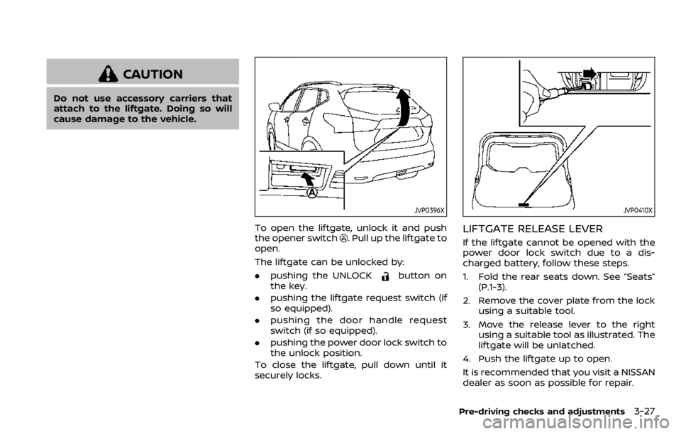
To open the liftgate, unlock it and push
the opener switch. Pull up the liftgate to
open.
The liftgate can be unlocked by:
. pushing the UNLOCK
button on
the key.
. pushing the liftgate request switch (if
so equipped).
. pushing the door handle request
switch (if so equipped).
. pushing the power door lock switch to
the unlock position.
To close the liftgate, pull down until it
securely locks.
JVP0410X
LIFTGATE RELEASE LEVER
If the liftgate cannot be opened with the
power door lock switch due to a dis-
charged battery, follow these steps.
1. Fold the rear seats down. See “Seats” (P.1-3).
2. Remove the cover plate from the lock using a suitable tool.
3. Move the release lever to the right using a suitable tool as illustrated. The
liftgate will be unlatched.
4. Push the liftgate up to open.
It is recommended that you visit a NISSAN
dealer as soon as possible for repair.
Pre-driving checks and adjustments3-27
Page 194 of 492
3-28Pre-driving checks and adjustments
WARNING
.Fuel is extremely flammable and
highly explosive under certain
conditions. You could be burned
or seriously injured if it is misused
or mishandled. Always stop the
engine and do not smoke or allow
open flames or sparks near the
vehicle when refueling.
. Fuel may be under pressure. Turn
the cap a half of a turn, and wait
for any “hissing” sound to stop to
prevent fuel from spraying out
and possibly causing personal
injury. Then remove the cap.
. Use only an original equipment
type fuel-filler cap as a replace-
ment. It has a built-in safety valve
needed for proper operation of
the fuel system and emission
control system. An incorrect cap
can result in a serious malfunc-
tion and possible injury.
JVP0540X
OPENING THE FUEL-FILLER DOOR
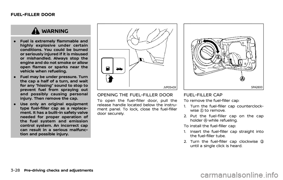
To open the fuel-filler door, pull the
release handle located below the instru-
ment panel. To lock, close the fuel-filler
door securely.
SPA2800
FUEL-FILLER CAP
To remove the fuel-filler cap:
1. Turn the fuel-filler cap counterclock-
wise
to remove.
2. Put the fuel-filler cap on the cap holder
while refueling.
To install the fuel-filler cap:
1. Insert the fuel-filler cap straight into the fuel-filler tube.
2. Turn the fuel-filler cap clockwise
until a single click is heard.
FUEL-FILLER DOOR
Page 195 of 492
WARNING
.Gasoline is extremely flammable
and highly explosive under cer-
tain conditions. You could be
burned or seriously injured if it is
misused or mishandled. Always
stop engine and do not smoke or
allow open flames or sparks near
the vehicle when refueling.
. Do not attempt to top off the fuel
tank after the fuel pump nozzle
shuts off automatically. Contin-
ued refueling may cause fuel
overflow, resulting in fuel spray
and possibly a fire.
. Use only an original equipment
type fuel-filler cap as a replace-
ment. It has a built-in safety valve
needed for proper operation of
the fuel system and emission
control system. An incorrect cap
can result in a serious malfunc-
tion and possible injury. It could
also cause the malfunction indi-
cator light to come on.
. Never pour fuel into the throttle
body to attempt to start your
vehicle. .
Do not fill a portable fuel contain-
er in the vehicle or trailer. Static
electricity can cause an explosion
of flammable liquid, vapor or gas
in any vehicle or trailer. To reduce
the risk of serious injury or death
when filling portable fuel contain-
ers:
— Always place the container on
the ground when filling.
— Do not use electronic devices when filling.
— Keep the pump nozzle in con- tact with the container while
you are filling it.
— Use only approved portable fuel containers for flammable
liquid.
CAUTION
. If fuel is spilled on the vehicle
body, flush it away with water to
avoid paint damage.
. Insert the cap straight into the
fuel-filler tube, then tighten until
the fuel-filler cap clicks. Failure to
tighten the fuel-filler cap properly
may cause the
malfunction indicator light (MIL) to illuminate.
If the
light illuminates be-
cause the fuel-filler cap is loose
or missing, tighten or install the
cap and continue to drive the
vehicle. The
light should turn
off after a few driving trips. If the
light does not turn off after a
few driving trips, have the vehicle
inspected. It is recommended you
visit a NISSAN dealer for this
service.
For additional information, see
“Malfunction Indicator Light
(MIL)” (P.2-17).
. The LOOSE FUEL CAP warning
message will be displayed if the
fuel-filler cap is not properly tigh-
tened. It may take a few driving
trips for the message to be dis-
played. Failure to tighten the fuel-
filler cap properly after the LOOSE
FUEL CAP warning message is
displayed may cause the
Malfunction Indicator Light (MIL)
to illuminate.
Pre-driving checks and adjustments3-29
Page 196 of 492

3-30Pre-driving checks and adjustments
JVP0503X
LOOSE FUEL CAP warning message
The LOOSE FUEL CAP warning messageis displayed on the vehicle information
display when the fuel-filler cap is not
tightened correctly after the vehicle has
been refueled. It may take a few driving
trips for the message to be displayed. To
turn off the warning message, do the
following procedure:
1. Remove and install the fuel-filler capas soon as possible. For additional
information, refer to “Fuel-filler cap”
(P.3-28).
2. Tighten the fuel-filler cap until it clicks. 3. Push the OK button
on the steering
wheel for about 1 second to turn off
the LOOSE FUEL CAP warning mes-
sage after tightening the fuel cap.
WARNING
Do not adjust the steering wheel
while driving. You could lose control
of your vehicle and cause an acci-
dent.
TILT/TELESCOPIC STEERING
Page 197 of 492

JVP0301X
TILT OR TELESCOPIC OPERATION
Pull the lock leverdown and adjust the
steering wheel up, down, forward or
rearward to the desired position. Push
the lock lever up securely to lock the
steering wheel in place.
SIC3739
1. To block glare from the front, swing down the main sun visor.
2. To block glare from the side, remove the main sun visor from the center
mount and swing it to the side
.
3. Slide the sun visor
in or out as
needed.
CAUTION
. Do not store the sun visor before
returning the extension to its
original position.
. Do not pull the extension sun
visor forcedly downward.
Pre-driving checks and adjustments3-31
SUN VISORS
Page 198 of 492
3-32Pre-driving checks and adjustments
SPA2447
INSIDE MIRROR
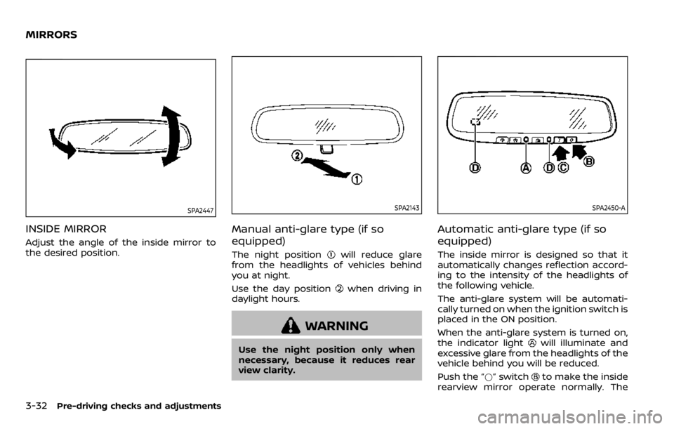
Adjust the angle of the inside mirror to
the desired position.
SPA2143
Manual anti-glare type (if so
equipped)
The night positionwill reduce glare
from the headlights of vehicles behind
you at night.
Use the day position
when driving in
daylight hours.
WARNING
Use the night position only when
necessary, because it reduces rear
view clarity.
SPA2450-A
Automatic anti-glare type (if so
equipped)
The inside mirror is designed so that it
automatically changes reflection accord-
ing to the intensity of the headlights of
the following vehicle.
The anti-glare system will be automati-
cally turned on when the ignition switch is
placed in the ON position.
When the anti-glare system is turned on,
the indicator light
will illuminate and
excessive glare from the headlights of the
vehicle behind you will be reduced.
Push the “*” switch
to make the inside
rearview mirror operate normally. The
MIRRORS
Page 199 of 492
indicator light will turn off. Push the “I”
switchto turn the system on.
Do not allow any object to cover the
sensors
or apply glass cleaner on
them. Doing so will reduce the sensitiv-
ity of the sensor, resulting in improper
operation.
For the HomeLink® Universal Transceiver
operation, see “HomeLink® Universal
Transceiver” (P.2-80).
OUTSIDE MIRRORS
WARNING
Objects viewed in the outside mirror
on the passenger side are closer
than they appear. Be careful when
moving to the right. Using only this
mirror could cause an accident. Use
the inside mirror or glance over your
shoulder to properly judge distances
to other objects.
JVP0395X
Adjusting outside mirrors
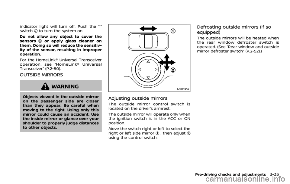
The outside mirror control switch is
located on the driver’s armrest.
The outside mirror will operate only when
the ignition switch is in the ACC or ON
position.
Move the switch right or left to select the
right or left side mirror
, then adjustusing the control switch.
Defrosting outside mirrors (if so
equipped)
The outside mirrors will be heated when
the rear window defroster switch is
operated. (See “Rear window and outside
mirror defroster switch” (P.2-52).)
Pre-driving checks and adjustments3-33
Page 200 of 492

3-34Pre-driving checks and adjustments
SPA1829
Foldable outside mirrors
Fold the outside mirror by pushing it
toward the rear of the vehicle.
SIC3869
VANITY MIRROR
To use the front vanity mirror, pull down
the sun visor and pull up the cover.The automatic drive positioner system
has two features:
.
Memory storage function
. Entry/exit function
AUTOMATIC DRIVE POSITIONER (if
so equipped)