battery location NISSAN QASHQAI 2020 Owner´s Manual
[x] Cancel search | Manufacturer: NISSAN, Model Year: 2020, Model line: QASHQAI, Model: NISSAN QASHQAI 2020Pages: 492, PDF Size: 2.02 MB
Page 179 of 492

SPA2074
INTELLIGENT KEY OPERATING
RANGE
The Intelligent Key functions can only be
used when the Intelligent Key is within
the specified operating range from the
request switch
.
When the Intelligent Key battery is dis-
charged or strong radio waves are pre-
sent near the operating location, the
Intelligent Key system’s operating range
becomes narrower, and the Intelligent
Key may not function properly.
The operating range is within 31.50 in (80
cm) from each request switch
.
If the Intelligent Key is too close to the door glass, handle or rear bumper, the
request switches may not function.
When the Intelligent Key is within the
operating range, it is possible for anyone
who does not carry the Intelligent Key to
push the request switch to lock/unlock
the doors including the liftgate.
SPA2407
DOOR LOCKS/UNLOCKS PRECAU-
TION
.
Do not push the door handle request
switch with the Intelligent Key held in
your hand as illustrated. The close
distance to the door handle will cause
the Intelligent Key system to have
difficulty recognizing that the Intelli-
gent Key is outside the vehicle.
. After locking with the door handle
request switch, verify the doors are
securely locked by testing them.
. To prevent the Intelligent Key from
being left inside the vehicle, make sure
you carry the key with you and then
lock the doors.
Pre-driving checks and adjustments3-13
Page 189 of 492

WARNING
To avoid risk of injury or death, do
not use the remote engine start
function when the vehicle is in an
enclosed area such as a garage.
JVP0446X
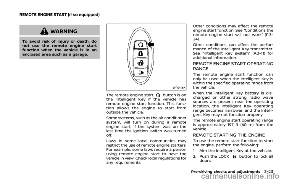
The remote engine startbutton is on
the Intelligent Key if the vehicle has
remote engine start function. This func-
tion allows the engine to start from
outside the vehicle.
Some systems, such as the air conditioner
system, will turn on during a remote
engine start, if the system was on the
last time the ignition switch was turned
off.
Laws in some local communities may
restrict the use of remote engine starters.
For example, some laws require a person
using remote engine start to have the
vehicle in view. Check local regulations for
any requirements. Other conditions may affect the remote
engine start function. See “Conditions the
remote engine start will not work” (P.3-
24).
Other conditions can affect the perfor-
mance of the Intelligent Key transmitter.
See “Intelligent Key system” (P.3-11) for
additional information.
REMOTE ENGINE START OPERATING
RANGE
The remote engine start function can
only be used when the Intelligent Key is
within the specified operating range from
the vehicle.
When the Intelligent Key battery is dis-
charged or other strong radio wave
sources are present near the operating
location, the Intelligent Key operating
range becomes narrower, and the Intelli-
gent Key may not function properly.
The remote engine start operating range
is approximately 197 ft (60 m) from the
vehicle.
REMOTE STARTING THE ENGINE
To use the remote start function to start
the engine, perform the following:
1. Aim the Intelligent Key at the vehicle.
2. Push the LOCK
button to lock all
doors.
Pre-driving checks and adjustments3-23
REMOTE ENGINE START (if so equipped)
Page 250 of 492

5-14Starting and driving
KEY POSITIONS
LOCK: Normal parking position (0)
OFF: (Not used) (1)
This position activates electrical acces-
sories such as the radio when the engine
is not running.
ON: Normal operating position (2)
This position turns on the ignition system
and the electrical accessories.
START: (3)
This position starts the engine. As soon as
the engine has started, release the key. It
automatically returns to the ON position.
WARNING
Do not operate the push-button
ignition switch while driving the ve-
hicle except in an emergency. (The
engine will stop when the ignition
switch is pushed 3 consecutive times
or the ignition switch is pushed and
held for more than 2 seconds.) If the
engine stops while the vehicle is
being driven, this could lead to a
crash and serious injury.
Before operating the push-button igni-
tion switch, be sure to move the shift
lever to the P (Park) position (for Con-
tinuously Variable Transmission (CVT)
models) or the shift lever to the N
(Neutral) position (for Manual Transmis-
sion (MT) models).
SSD0436
OPERATING RANGE FOR ENGINE
START FUNCTION
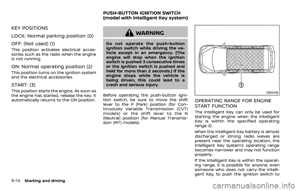
The Intelligent Key can only be used for
starting the engine when the Intelligent
Key is within the specified operating
range
.
When the Intelligent Key battery is almost
discharged or strong radio waves are
present near the operating location, the
Intelligent Key system’s operating range
becomes narrower and may not function
properly.
If the Intelligent Key is within the operat-
ing range, it is possible for anyone, even
someone who does not carry the Intelli-
gent Key, to push the ignition switch to
PUSH-BUTTON IGNITION SWITCH
(model with Intelligent Key system)
Page 407 of 492

8 Do-it-yourself
Maintenance precautions ...................................................... 8-2
Engine compartment check locations ........................ 8-3MR20DD engine model ..................................................... 8-4
Engine cooling system ............................................................. 8-4 Checking engine coolant level .................................... 8-5
Changing engine coolant ................................................ 8-6
Engine oil ........................................................................\
..................... 8-6 Checking engine oil level ................................................. 8-6
Changing engine oil and filter ..................................... 8-6
Continuously Variable Transmission (CVT)
fluid ........................................................................\
.................................. 8-9
Brake and clutch (if so equipped) fluid ....................... 8-9
Window washer fluid .............................................................. 8-10
Battery ........................................................................\
........................ 8-11 Jump starting ........................................................................\
. 8-12
Variable voltage control system ................................... 8-13
Drive belt ........................................................................\
.................. 8-13
Spark plugs ........................................................................\
............. 8-14 Replacing spark plugs ..................................................... 8-14
Air cleaner ........................................................................\
............... 8-15
Air duct removal .................................................................. 8-15
Air cleaner filter replacement ................................... 8-15 Windshield wiper blades ..................................................... 8-16
Cleaning ........................................................................\
........... 8-16
Replacing ........................................................................\
........ 8-16
Rear window wiper blade .................................................. 8-17
Brakes ........................................................................\
........................ 8-17 Self-adjusting brakes ..................................................... 8-17
Brake pad wear warning ............................................ 8-17
Fuses ........................................................................\
........................... 8-18 Engine compartment .................................................... 8-18
Passenger compartment ........................................... 8-20
Key fob battery replacement .......................................... 8-21
Intelligent Key battery replacement .......................... 8-23
Lights ........................................................................\
.......................... 8-25 Headlights ........................................................................\
...... 8-25
Exterior and interior lights ........................................ 8-27
Wheels and tires ........................................................................\
8-29
Tire pressure ........................................................................\
8-29
Tire labeling ........................................................................\
.. 8-33
Types of tires ....................................................................... 8-35
Tire chains ........................................................................\
...... 8-36
Changing wheels and tires ...................................... 8-37
Page 409 of 492

off and wait until it cools down.
. Avoid direct contact with used
engine oil and coolant. Impro-
perly disposed engine oil, and
engine coolant and/or other ve-
hicle fluids can damage the en-
vironment. Always conform to
local regulations for disposal of
vehicle fluid.
. Never leave the engine or the CVT
related component harnesses
disconnected while the ignition
switch is in the ON position.
. Never connect or disconnect the
battery or any transistorized
component while the ignition
switch is in the ON position.
. Your vehicle is equipped with an
automatic engine cooling fan. It
may come on at any time without
warning, even if the ignition key is
in the OFF position and the en-
gine is not running. To avoid
injury, always disconnect the ne-
gative battery cable before work-
ing near the fan.
This “8. Do-it-yourself” section gives in-
structions regarding only those items
which are relatively easy for an owner to
perform. A genuine NISSAN Service Manual is also
available. (See “Owner’s manual/service
manual order information” (P.10-20).)
You should be aware that incomplete or
improper servicing may result in operat-
ing difficulties or excessive emissions, and
could affect your warranty coverage.
If in
doubt about any servicing, it is recom-
mended you have it done by a NISSAN
dealer.
JVM0610X
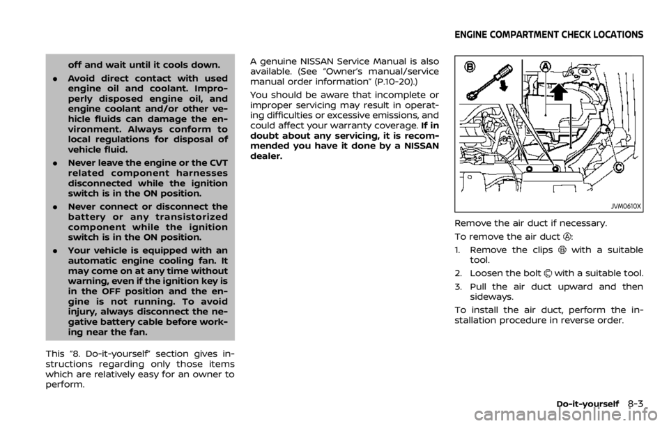
Remove the air duct if necessary.
To remove the air duct
:
1. Remove the clips
with a suitable
tool.
2. Loosen the bolt
with a suitable tool.
3. Pull the air duct upward and then sideways.
To install the air duct, perform the in-
stallation procedure in reverse order.
Do-it-yourself8-3
ENGINE COMPARTMENT CHECK LOCATIONS