NISSAN QASHQAI 2023 Owners Manual
Manufacturer: NISSAN, Model Year: 2023, Model line: QASHQAI, Model: NISSAN QASHQAI 2023Pages: 508, PDF Size: 2.47 MB
Page 201 of 508
JVP0301X
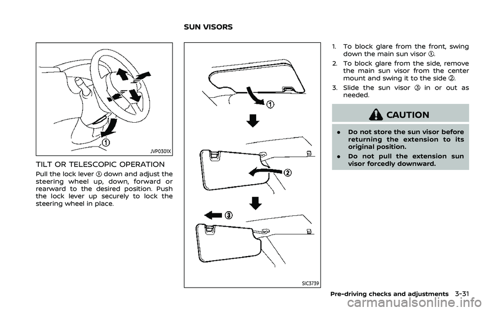
TILT OR TELESCOPIC OPERATION
Pull the lock leverdown and adjust the
steering wheel up, down, forward or
rearward to the desired position. Push
the lock lever up securely to lock the
steering wheel in place.
SIC3739
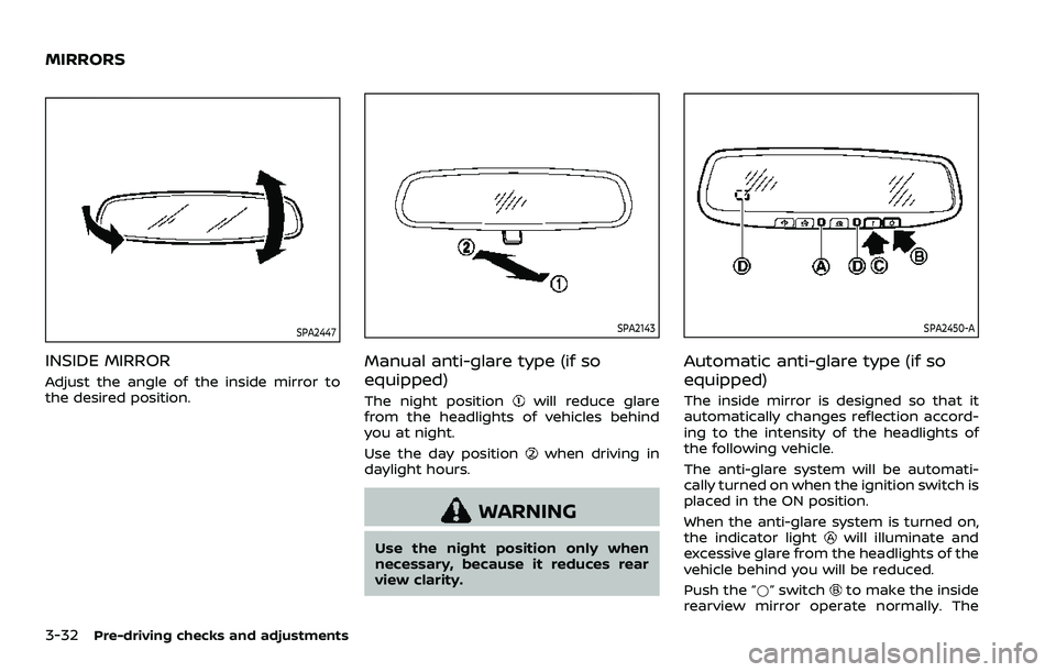
1. To block glare from the front, swing down the main sun visor.
2. To block glare from the side, remove the main sun visor from the center
mount and swing it to the side
.
3. Slide the sun visor
in or out as
needed.
CAUTION
. Do not store the sun visor before
returning the extension to its
original position.
. Do not pull the extension sun
visor forcedly downward.
Pre-driving checks and adjustments3-31
SUN VISORS
Page 202 of 508
3-32Pre-driving checks and adjustments
SPA2447
INSIDE MIRROR
Adjust the angle of the inside mirror to
the desired position.
SPA2143
Manual anti-glare type (if so
equipped)
The night positionwill reduce glare
from the headlights of vehicles behind
you at night.
Use the day position
when driving in
daylight hours.
WARNING
Use the night position only when
necessary, because it reduces rear
view clarity.
SPA2450-A
Automatic anti-glare type (if so
equipped)
The inside mirror is designed so that it
automatically changes reflection accord-
ing to the intensity of the headlights of
the following vehicle.
The anti-glare system will be automati-
cally turned on when the ignition switch is
placed in the ON position.
When the anti-glare system is turned on,
the indicator light
will illuminate and
excessive glare from the headlights of the
vehicle behind you will be reduced.
Push the “*” switch
to make the inside
rearview mirror operate normally. The
MIRRORS
Page 203 of 508
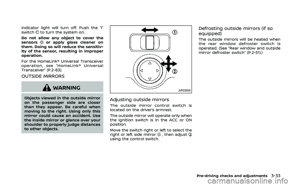
indicator light will turn off. Push the “I”
switchto turn the system on.
Do not allow any object to cover the
sensors
or apply glass cleaner on
them. Doing so will reduce the sensitiv-
ity of the sensor, resulting in improper
operation.
For the HomeLink® Universal Transceiver
operation, see “HomeLink® Universal
Transceiver” (P.2-83).
OUTSIDE MIRRORS
WARNING
Objects viewed in the outside mirror
on the passenger side are closer
than they appear. Be careful when
moving to the right. Using only this
mirror could cause an accident. Use
the inside mirror or glance over your
shoulder to properly judge distances
to other objects.
JVP0395X
Adjusting outside mirrors
The outside mirror control switch is
located on the driver’s armrest.
The outside mirror will operate only when
the ignition switch is in the ACC or ON
position.
Move the switch right or left to select the
right or left side mirror
, then adjustusing the control switch.
Defrosting outside mirrors (if so
equipped)
The outside mirrors will be heated when
the rear window defroster switch is
operated. (See “Rear window and outside
mirror defroster switch” (P.2-51).)
Pre-driving checks and adjustments3-33
Page 204 of 508
3-34Pre-driving checks and adjustments
SPA1829
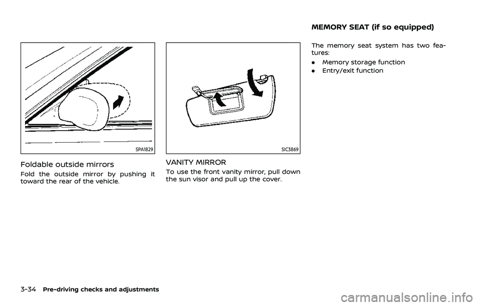
Foldable outside mirrors
Fold the outside mirror by pushing it
toward the rear of the vehicle.
SIC3869
VANITY MIRROR
To use the front vanity mirror, pull down
the sun visor and pull up the cover.The memory seat system has two fea-
tures:
.
Memory storage function
. Entry/exit function
MEMORY SEAT (if so equipped)
Page 205 of 508
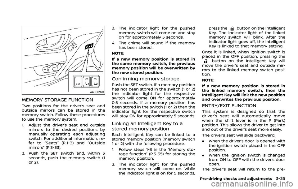
WAD0097X
MEMORY STORAGE FUNCTION
Two positions for the driver’s seat and
outside mirrors can be stored in the
memory switch. Follow these procedures
to use the memory system.
1. Adjust the driver’s seat and outsidemirrors to the desired positions by
manually operating each adjusting
switch. For additional information, re-
fer to “Seats” (P.1-3) and “Outside
mirrors” (P.3-33).
2. Push the SET switch and, within 5 seconds, push the memory switch (1
or 2). 3. The indicator light for the pushed
memory switch will come on and stay
on for approximately 5 seconds.
4. The chime will sound if the memory has been stored.
NOTE:
If a new memory position is stored in
the same memory switch, the previous
memory position will be overwritten by
the new stored position.
Confirming memory storage
Push the SET switch. If a memory position
has not been stored in the switch (1 or 2)
the indicator light for the respective
switch will come ON for approximately
0.5 seconds. If a memory position has
been stored in the switch (1 or 2) then the
indicator light for the respective switch
will stay ON for approximately 5 seconds.
Linking an Intelligent Key to a
stored memory position
Each Intelligent Key can be linked to a
stored memory position (memory switch
1 or 2) with the following procedure.
1. Follow steps 1-3 in the “Memory sto- rage function” (P.3-35) for storing the
memory position.
2. The indicator light for the pushed memory switch will come on. While
the indicator light is on for 5 seconds, press the
button on the Intelligent
Key. The indicator light of the linked
memory switch will blink. After the
indicator light goes off, the Intelligent
Key is linked to that memory setting.
Once it is linked, when ignition switch is
placed in the OFF position, pressing the
button on the Intelligent Key will
move the driver’s seat and outside mir-
rors to the linked memory switch posi-
tion.
NOTE:
If a new memory position is stored in
the linked memory switch, then the
Intelligent Key will link the new position
and overwrites the previous position.
ENTRY/EXIT FUNCTION
This system is designed so that the
driver’s seat will automatically move
when the shift lever is in the P (Park)
position. This allows the driver to get into
and out of the driver’s seat more easily.
The driver’s seat will slide backward:
. When the driver’s door is opened with
the ignition switch placed in the OFF
position.
. When the ignition switch is changed
from ON to OFF with the driver’s door
open.
The driver’s seat will return to the pre-
Pre-driving checks and adjustments3-35
Page 206 of 508
3-36Pre-driving checks and adjustments
vious position:
.When the ignition switch is turned to
ON while the shift lever is in the P
(Park) position.
The entry/exit function can be adjusted
or canceled through “Vehicle Settings” in
the vehicle information display by per-
forming the following:
. Switch the “Exit Seat Slide” from ON to
OFF. For additional information, refer
to “Vehicle Settings” (P.2-23).
SYSTEM OPERATION
The memory seat system will not work or
will stop operating under the following
conditions:
.When the vehicle is moving. (The
driver’s seat returning function can
be operated if the vehicle speed is
below 4 MPH (7 km/h).)
. When any of the memory switches are
pushed while the memory seat is
operating.
. When the switch for the driver’s seat is
pushed while the memory seat is
operating.
. When the seat has already been
moved to the memorized position.
. When no seat position is stored in the
memory switch. .
When the shift lever is moved from P
(Park) to any other position.
Page 207 of 508
4 Monitor, heater, air conditioner, audioand phone systems
NissanConnect® Owner’s Manual .................................... 4-2
RearView Monitor (if so equipped) ................................. 4-3
RearView Monitor system operation ..................... 4-4
How to read the displayed lines ................................ 4-4
Difference between predictive and
actual distances ...................................................................... 4-4
How to park with predictive course lines .......... 4-6
Adjusting the screen ........................................................... 4-8
How to turn ON and OFF predictive course
lines ........................................................................\
......................... 4-8
RearView Monitor system limitations .................... 4-8
System maintenance .......................................................... 4-9
Intelligent Around View® Monitor (if
so equipped) ........................................................................\
.......... 4-10 Intelligent Around View® Monitor
system operation ................................................................ 4-11
Difference between predictive and
actual distances ................................................................... 4-14
How to park with predictive course lines ....... 4-16
How to switch the display ........................................... 4-17
Adjusting the screen ........................................................ 4-18 Intelligent Around View® Monitor
system limitations ............................................................ 4-18
System maintenance .................................................... 4-20
Moving Object Detection (MOD) (if
so equipped) ........................................................................\
......... 4-21 MOD system operation ................................................ 4-22
Turning MOD on and off ............................................ 4-23
MOD system limitations .............................................. 4-23
System maintenance .................................................... 4-24
Ventilators ........................................................................\
.............. 4-25
Center ventilators ............................................................ 4-25
Side ventilators .................................................................. 4-25
Rear ventilators (if so equipped) .......................... 4-26
Heater and air conditioner ................................................ 4-26 Manual air conditioner and heater .................... 4-27
Automatic air conditioner and heater ............ 4-30
Operating tips (for automatic
air conditioner) ................................................................... 4-33
Servicing air conditioner ............................................. 4-33
Antenna ........................................................................\
.................... 4-33
Car phone or CB radio ......................................................... 4-34
Page 208 of 508
4-2Monitor, heater, air conditioner, audio and phone systems
WAE0859X
For models with NissanConnect® system,
refer to the digital NissanConnect® Own-
er’s Manual using the QR code on this
page (US only), or your printed Nissan-
Connect® Owner’s Manual (if so
equipped). This manual includes the fol-
lowing information.
Available functions may vary depending
on the models and specifications.
.Audio
. Hands-Free Phone
. Apple CarPlay®
. Android Auto
TM
.NissanConnect® Services powered by
SiriusXM® .
Navigation system
. Voice recognition
. Information and settings viewable on
NissanConnect®
NISSANCONNECT® OWNER’S MANUAL
Page 209 of 508
WAE0016X
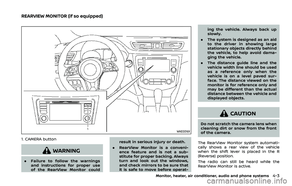
1. CAMERA button
WARNING
.Failure to follow the warnings
and instructions for proper use
of the RearView Monitor could result in serious injury or death.
. RearView Monitor is a conveni-
ence feature and is not a sub-
stitute for proper backing. Always
turn and look out the windows,
and check mirrors to be sure that
it is safe to move before operat- ing the vehicle. Always back up
slowly.
. The system is designed as an aid
to the driver in showing large
stationary objects directly behind
the vehicle, to help avoid dama-
ging the vehicle.
. The distance guide line and the
vehicle width line should be used
as a reference only when the
vehicle is on a level paved sur-
face. The distance viewed on the
monitor is for reference only and
may be different than the actual
distance between the vehicle and
displayed objects.
CAUTION
Do not scratch the camera lens when
cleaning dirt or snow from the front
of the camera.
The RearView Monitor system automati-
cally shows a rear view of the vehicle
when the shift lever is placed in the R
(Reverse) position.
The radio can still be heard while the
RearView Monitor is active.
Monitor, heater, air conditioner, audio and phone systems4-3
REARVIEW MONITOR (if so equipped)
Page 210 of 508
4-4Monitor, heater, air conditioner, audio and phone systems
JVH1585X
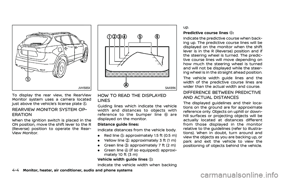
To display the rear view, the RearView
Monitor system uses a camera located
just above the vehicle’s license plate
.
REARVIEW MONITOR SYSTEM OP-
ERATION
When the ignition switch is placed in the
ON position, move the shift lever to the R
(Reverse) position to operate the Rear-
View Monitor.
SAA1896
HOW TO READ THE DISPLAYED
LINES
Guiding lines which indicate the vehicle
width and distances to objects with
reference to the bumper line
are
displayed on the monitor.
Distance guide lines:
Indicate distances from the vehicle body.
. Red line
: approximately 1.5 ft (0.5 m)
. Yellow line
: approximately 3 ft (1 m)
. Green line
: approximately 7 ft (2 m)
. Green line
(if so equipped): approxi-
mately 10 ft (3 m)
Vehicle width guide lines
:
Indicate the vehicle width when backing up.
Predictive course lines
:
Indicate the predictive course when back-
ing up. The predictive course lines will be
displayed on the monitor when the shift
lever is in the R (Reverse) position and if
the steering wheel is turned. The predic-
tive course lines will move depending on
how much the steering wheel is turned
and will not be displayed while the steer-
ing wheel is in the straight ahead position.
The vehicle width guide lines and the
width of the predictive course lines are
wider than the actual width and course.
DIFFERENCE BETWEEN PREDICTIVE
AND ACTUAL DISTANCES
The displayed guidelines and their loca-
tions on the ground are for approximate
reference only. Objects on uphill or down-
hill surfaces or projecting objects will be
actually located at distances different
from those displayed in the monitor
relative to the guidelines (refer to illustra-
tions). When in doubt, turn around and
view the objects as you are backing up, or
park and exit the vehicle to view the
positioning of objects behind the vehicle.