wheel NISSAN QUEST 1997 V40 / 1.G Owners Manual
[x] Cancel search | Manufacturer: NISSAN, Model Year: 1997, Model line: QUEST, Model: NISSAN QUEST 1997 V40 / 1.GPages: 247, PDF Size: 2.01 MB
Page 21 of 247

3. Use the autolamp switch to activate the
autolamp feature. It is to the left of the
steering wheel.
4. Turn the switch to the right. A slight
detent in the switch indicates it has been
turned past the off position. After the
switch is turned past the detent, the
autolamp automatically turns the lamps
on and off.
Shut-off delay
The length of time the autolamps stay on
after the ignition is turned to OFF depends
on how far the switch is turned to the right.
If the switch is turned all the way to the right,
the headlights stay on about three minutes
after the ignition is turned to OFF. If the
switch is turned only a little way to the right,
the headlights may stay on for less than a
minute.
To turn the autolamp system off, turn the
switch all the way to the left until the detent
is felt.Be sure you do not put anything on top
of the photo sensor located in the top
right side of the instrument panel. The
photo sensor controls the autolamp; if it
is covered, the photo sensor reacts as if
it is dark out and the headlights will
illuminate.
Turn signal
Move the lever up or down to signal the
turning direction. When the turn is com-
pleted, the turn signal cancels automati-
cally.
Lane change signal
To indicate a lane change, move the lever
up or down to the point where the light
begins to flash, but the lever does not latch.
Passing signal
Pulling the lever toward you turns the head-
light high beam on. Release it and the
headlight high beam goes off.
AIC0584AIC0560
TURN SIGNAL SWITCH
1-14
ZX
Page 34 of 247

Flexible seating .................................................2-32
Sliding three-passenger seat ...............................2-38
Supplemental restraint system (supplemental
air bag system).....................................................2-42
Supplemental air bag system...............................2-45
Warning labels......................................................2-47
Supplemental air bag warning light......................2-47
Seat belts .............................................................2-49
Precautions on seat belt usage ...........................2-49
Child safety...........................................................2-50
3-point type with retractor ....................................2-51
3-point type seat belt with retractor for second
row bucket seats ..................................................2-53
Three-passenger bench seat ...............................2-57
2-point type without retractor (center of
three-passenger bench seat) ...............................2-58
Seat belt extenders ..............................................2-60
Seat belt maintenance .........................................2-60Child restraints for infants and small children......2-60
Installation at three-passenger bench seat
center position ......................................................2-62
Installation at second and third row outboard
positions ...............................................................2-63
Child restraint with top tether strap ......................2-65
Installation on second row bench or bucket
seat .......................................................................2-66
Installation on three-passenger bench seat in
second row ...........................................................2-67
Installation on three-passenger bench seat in
third row................................................................2-68
Integrated child safety seats (if so equipped) ......2-71
Tilting steering wheel ...........................................2-78
Outside mirror control...........................................2-79
Outside mirrors .....................................................2-80
Inside mirror .........................................................2-80
Vanity mirror .........................................................2-80
ZX
Page 75 of 247

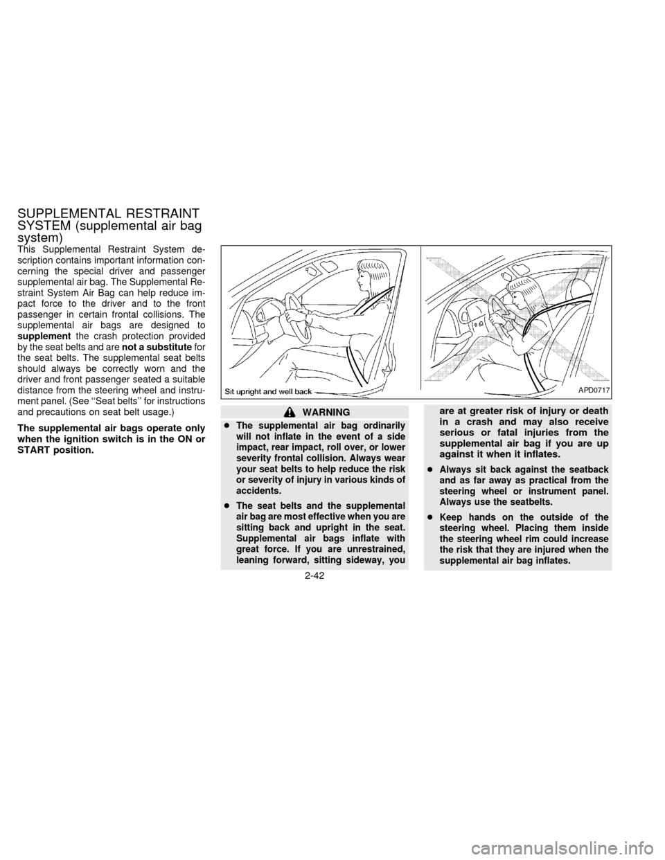
This Supplemental Restraint System de-
scription contains important information con-
cerning the special driver and passenger
supplemental air bag. The Supplemental Re-
straint System Air Bag can help reduce im-
pact force to the driver and to the front
passenger in certain frontal collisions. The
supplemental air bags are designed to
supplementthe crash protection provided
by the seat belts and arenot a substitutefor
the seat belts. The supplemental seat belts
should always be correctly worn and the
driver and front passenger seated a suitable
distance from the steering wheel and instru-
ment panel. (See ``Seat belts'' for instructions
and precautions on seat belt usage.)
The supplemental air bags operate only
when the ignition switch is in the ON or
START position.
WARNING
c
The supplemental air bag ordinarily
will not inflate in the event of a side
impact, rear impact, roll over, or lower
severity frontal collision. Always wear
your seat belts to help reduce the risk
or severity of injury in various kinds of
accidents.
cThe seat belts and the supplemental
air bag are most effective when you are
sitting back and upright in the seat.
Supplemental air bags inflate with
great force. If you are unrestrained,
leaning forward, sitting sideway, you
are at greater risk of injury or death
in a crash and may also receive
serious or fatal injuries from the
supplemental air bag if you are up
against it when it inflates.
c
Always sit back against the seatback
and as far away as practical from the
steering wheel or instrument panel.
Always use the seatbelts.
cKeep hands on the outside of the
steering wheel. Placing them inside
the steering wheel rim could increase
the risk that they are injured when the
supplemental air bag inflates.
APD0717
SUPPLEMENTAL RESTRAINT
SYSTEM (supplemental air bag
system)
2-42
ZX
Page 78 of 247

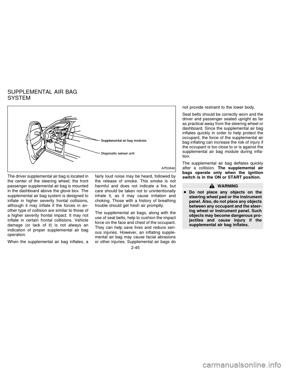
The driver supplemental air bag is located in
the center of the steering wheel; the front
passenger supplemental air bag is mounted
in the dashboard above the glove box. The
supplemental air bag system is designed to
inflate in higher severity frontal collisions,
although it may inflate if the forces in an-
other type of collision are similar to those of
a higher severity frontal impact. It may not
inflate in certain frontal collisions. Vehicle
damage (or lack of it) is not always an
indication of proper supplemental air bag
operation.
When the supplemental air bag inflates, afairly loud noise may be heard, followed by
the release of smoke. This smoke is not
harmful and does not indicate a fire, but
care should be taken not to unintentionally
inhale it, as it may cause irritation and
choking. Those with a history of breathing
trouble should get fresh air promptly.
The supplemental air bags, along with the
use of seat belts, help to cushion the impact
force on the face and chest of the occupant.
They can help save lives and reduce seri-
ous injuries. However, an inflating supple-
mental air bag may cause facial abrasions
or other injuries. Supplemental air bags donot provide restraint to the lower body.
Seat belts should be correctly worn and the
driver and passenger seated upright as far
as practical away from the steering wheel or
dashboard. Since the supplemental air bag
inflates quickly in order to help protect the
occupant, the force of the supplemental air
bag inflating can increase the risk of injury if
the occupant is too close to or is against the
supplemental air bag module during infla-
tion.
The supplemental air bag deflates quickly
after a collision.The supplemental air
bags operate only when the ignition
switch is in the ON or START position.
WARNING
cDo not place any objects on the
steering wheel pad or the instrument
panel. Also, do not place any objects
between any occupant and the steer-
ing wheel or instrument panel. Such
objects may become dangerous pro-
jectiles and cause injury if the
supplemental air bag inflates.
APD0846
SUPPLEMENTAL AIR BAG
SYSTEM
2-45
ZX
Page 79 of 247

cRight after inflation, several supple-
mental air bag system components
will be hot. Do not touch them; you
may severely burn yourself.
cNo unauthorized changes should be
made to any components or wiring
of the supplemental air bag system.
This is to prevent accidental inflation
of the supplemental air bag or dam-
age to the supplemental air bag
system.
cDo not make unauthorized changes
to your vehicles electrical system,
suspension system or front end
structure. This could affect proper
operation of the supplemental air
bag system.
cTampering with the supplemental air
bag system may result in serious
personal injury. Tampering includes
changes to the steering wheel and
the instrument panel assembly by
placing material over the steering
wheel pad and above the instrument
panel, or by installing additional trim
material around the supplemental air
bag system.cWork around and on the supplemen-
tal air bag system should be done by
an authorized NISSAN dealer. Instal-
lation of electrical equipment should
also be done by an authorized NIS-
SAN dealer. The yellow SRS wiring
should not be modified or discon-
nected. Unauthorized electrical test
equipment and probing devices
should not be used on the supple-
mental air bag system.
cThe SRS wiring harnesses are cov-
ered with yellow insulation either
just before the harness connectors
or over the complete harness for
easy identification.
When selling your vehicle, we request that
you inform the buyer about the supplemen-
tal air bag system and guide the buyer to the
appropriate sections in this Owner's
Manual.
2-46
ZX
Page 111 of 247

Integrated Child Safety Seat main-
tenance
cTo clean the shoulder harnesses and belt
buckle webbing, apply a mild soap solu-
tion or any solution recommended for
cleaning upholstery or carpets. Then
brush the webbing, wipe it with a cloth
and allow it to dry in the shade. Do not
allow the shoulder harnesses to retract
until they are completely dry.
cThe integrated child safety seats cloth
removable pads may be cleaned with
mild soap and water. The cloth remov-
able pads are attached to the seats with
fastener strips, and may be easily re-
moved. The pads are machine washable.
Fo best results, machine wash in cold
water in the gentle cycle. Tumble dry on
low heat. Do not use chlorine bleach, and
do not dry clean.
CAUTION
Failure to follow the washing instruc-
tions provided on the cloth removable
pads may result in premature wear or
damage.cPeriodically inspect the belt and metal
components of the integrated child safety
seats, such as the buckles, tongues,
shoulder harness webbings, and latching
indicators. Periodically check the func-
tion of the integrated child safety seat
shoulder harness retractor functions. If
loose parts, deterioration, cuts, frays,
malfunctions or other damage to the belt
webbings or metal parts are found, see
your NISSAN dealer for repairs.
Inspection after an accident
If your vehicle was involved in an accident,
before using the integrated child safety
seats, all related components should be
inspected by a NISSAN dealer for damage.
Damage to the integrated child safety seats
or related components must be repaired.Push the lock lever down and adjust the
steering wheel up or down to the desired
position. Pull the lock lever up firmly to lock
the steering wheel in place.
Gently pull down on the wheel to be sure it
is properly locked.
WARNING
Do not adjust the steering wheel while
driving. You could lose control of your
vehicle and cause an accident.
APD0812
TILTING STEERING WHEEL
2-78
ZX
Page 114 of 247

3Heater, air conditioner and audio system
Ventilators ..............................................................3-2
Heater and air conditioner (manual) ......................3-3
Controls ..................................................................3-3
Heater operation ....................................................3-4
Air conditioner operation ........................................3-5
Air flow charts.........................................................3-7
Heater and air conditioner (automatic) (if so
equipped) .............................................................3-10
Automatic operation .............................................3-11
Air control buttons ................................................3-11
Air conditioner and air recirculation .....................3-12
English/metric mode .............................................3-12
Rear seat heater and air conditioner (if so
equipped) .............................................................3-13Controls ................................................................3-13
Audio system ........................................................3-14
AM-FM radio with cassette player .......................3-14
Tuning
..................................................................3-16
Adjusting tone quality ...........................................3-17
Cassette tape operations .....................................3-18
Antenna ................................................................3-20
Compact disc (CD) player (if so equipped) .........3-21
Steering wheel controls ........................................3-23
Rear audio controls ..............................................3-24
CB radio or car phone..........................................3-25
ZX
Page 123 of 247

WARNING
cThe air conditioner cooling function
operates only when the engine is
running.
cDo not leave children, unreliable
adults, or pets alone in your vehicle.
On hot, sunny days, temperatures in
a closed vehicle could quickly be-
come high enough to cause severe
or possibly fatal injuries to people or
animals.cDo not use the recirculation mode
for long periods as it may cause the
interior air to become stale and the
windows to fog up.
cPositioning of the heater and air con-
ditioner controls should not be done
while driving, in order that full atten-
tion may be given to the driving
operation.
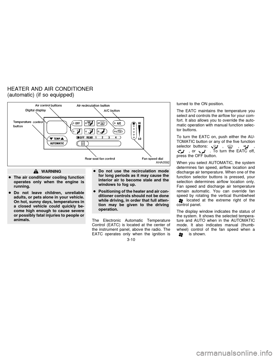
The Electronic Automatic Temperature
Control (EATC) is located at the center of
the instrument panel, above the radio. The
EATC operates only when the ignition isturned to the ON position.
The EATC maintains the temperature you
select and controls the airflow for your com-
fort. It also allows you to override the auto-
matic operation with manual function selec-
tor buttons.
To turn the EATC on, push either the AU-
TOMATIC button or any of the five function
selector buttons:
,,,
,or. To turn the EATC off,
press the OFF button.
When you select AUTOMATIC, the system
determines fan speed, airflow location and
discharge air temperature. When one of the
function selector buttons is pressed, your
selection determines airflow location only.
Fan speed and discharge air temperature
remain automatic. You can override fan
speed by rotating the vertical thumbwheel
located at the extreme right of the
control panel.
The display window indicates the status of
the system. It shows the selected tempera-
ture and AUTO when in the AUTOMATIC
mode. It also indicates manual (thumb-
wheel) control of the fan speed when a
is shown.
AHA0592
HEATER AND AIR CONDITIONER
(automatic) (if so equipped)
3-10
ZX
Page 124 of 247

AUTOMATIC OPERATION
Push the AUTOMATIC button and select
the desired temperature. The selected tem-
perature and AUTO show in the display
window. The EATC heats or cools to
achieve the set temperature.
When in AUTOMATIC and weather condi-
tions require heat, air is sent to the floor.
However, a feature is included in the EATC
to prevent blowing cold air to the floor if the
engine coolant is not warm enough to allow
heating. In three or four minutes the fan
speed gradually increases and airflow
changes to the floor.
If unique conditions exist, such as window
fogging, the five override buttons allow spe-
cific airflow selection. The thumbwheel al-
lows you to adjust the fan speed to suit your
needs.
Temperature selection
TheTEMPbutton on the left
side of the control panel is for temperature
selection. The
side lowers the set
temperature, and theside raises the
set temperature. Press and hold either side
of the button to rapidly change the tempera-
ture setting in one degree increments toeither 65ÉF (18ÉC) or 85ÉF (29ÉC). If you
want continuous maximum cooling, push
the
side of the TEMP button until
60ÉF (16ÉC) shows in the display window.
The EATC cools at maximum and disre-
gards the 60ÉF (16ÉC) setting until a warmer
temperature is selected. If you want con-
tinuous maximum heating, push the
side of the TEMP button until 90ÉF
(32ÉC) shows in the display window. The
EATC provides maximum heat regardless
of the 90ÉF (32ÉC) setting until a cooler
temperature is selected.
Fan speed and thumbwheel
Your EATC automatically adjusts the fan
speed to the existing conditions. To control
the fan speed yourself, use the thumbwheel
located at the extreme right side of the
EATC control panel. Using the thumbwheel
cancels the automatic fan speed control,
and causes a
to appear in the display
window. Rotate the thumbwheel up for HI
speeds and down for LO speeds.
To return to auto fan control, press the
AUTOMATIC button.
AIR CONTROL BUTTONS
Your EATC has five buttons which allow youto make special selections. The buttons are
grouped in the middle of the EATC panel
and allow you to determine airflow location.
Pressing any of the air control buttons
changes airflow location only, and does not
affect the ability of the system to control
temperature or fan speed. Return to fully
automatic operation by pushing the AUTO-
MATIC button.
Push this button for airflow to the floor and
windshield at the same time. Thein-
dicator light comes on, and the display
window shows the set temperature.
Press this button to obtain maximum airflow
to the windshield. Adjust the temperature
setting as required for defrosting. The
indicator light comes on, and the
display window shows the set temperature.
When the outside temperature is about
50ÉF (10ÉC) or above, the air is dehumidi-
fied to prevent window fogging.
Push this button to select airflow through
the instrument panel registers. The
indicator light comes on, and the
display window shows the set temperature.
3-11
ZX
Page 125 of 247

The EATC heats the air if the selected
temperature is warmer than the outside air
coming into the vehicle. However, the air is
not cooled regardless of the temperature
setting.
Push this button to get air from the floor and
instrument panel registers at the same time.
The
indicator light comes on and the
display window shows the set temperature.
Depending on the selected temperature, the
air is automatically heated or cooled.
Push this button to direct airflow to the floor.
Theindicator light comes on, and the
display window shows the set temperature.
The air cannot be cooled in the
mode, only heated.
AIR CONDITIONER AND AIR RE-
CIRCULATION
Activate the air conditioner in any of the
override modes listed above by pressing the
A/C button. The A/C indicator light comes
on to verify activation, and cooled air flows
from the vents. Fan speed continues to be
controlled by the EATC unless the fan
speed thumbwheel is used to override.Press the
button to choose air recir-
culation. In this mode the EATC system
recirculates the air inside the vehicle rather
than drawing air from outside. Use this
mode together with the air conditioner to
rapidly cool the inside of the vehicle, or to
dehumidify the air inside the vehicle.
ENGLISH/METRIC MODE
Switch from English to metric temperature
display by simultaneously pressing the
and A/C buttons and holding the
thumbwheel in upper position (HI) for one
second.
AHA762
3-12
ZX