height NISSAN QUEST 1999 V41 / 2.G Owners Manual
[x] Cancel search | Manufacturer: NISSAN, Model Year: 1999, Model line: QUEST, Model: NISSAN QUEST 1999 V41 / 2.GPages: 286, PDF Size: 2.46 MB
Page 12 of 286

Seat height adjustment
To raise the height of the seat, lift the power
seat height switch and release it when the
desired position is reached. To lower the
height of the seat, push the power seat
height switch down and release it when the
desired position is reached.
Lumbar support
The lumbar support provides lower back
support to the driver. Move the lever up or
down to adjust the seat lumbar area.
ARS1120ARS1158ARS1121
Seats, restraints and supplemental air bag systems1-5
ZX
Page 38 of 286
To increase your confidence in the seat
belts, check their operation as follows.
cGrasp the shoulder belt and pull quickly
forward. The retractor should lock and
restrict further belt movement.
If the retractor does not lock during this
check or if you have any questions about
belt operation, see an authorized NISSAN
dealer.
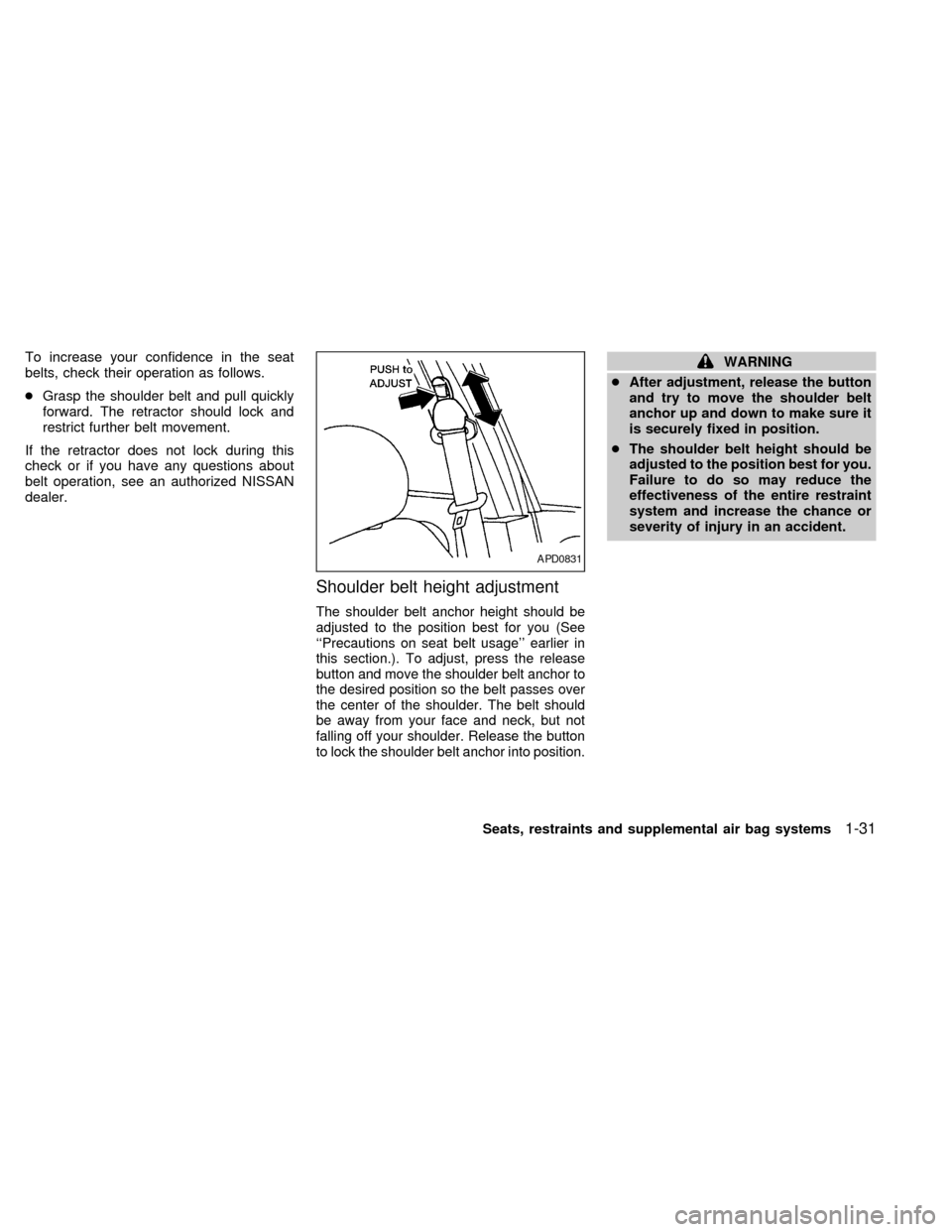
Shoulder belt height adjustment
The shoulder belt anchor height should be
adjusted to the position best for you (See
``Precautions on seat belt usage'' earlier in
this section.). To adjust, press the release
button and move the shoulder belt anchor to
the desired position so the belt passes over
the center of the shoulder. The belt should
be away from your face and neck, but not
falling off your shoulder. Release the button
to lock the shoulder belt anchor into position.
WARNING
cAfter adjustment, release the button
and try to move the shoulder belt
anchor up and down to make sure it
is securely fixed in position.
cThe shoulder belt height should be
adjusted to the position best for you.
Failure to do so may reduce the
effectiveness of the entire restraint
system and increase the chance or
severity of injury in an accident.
APD0831
Seats, restraints and supplemental air bag systems1-31
ZX
Page 68 of 286
INTEGRATED CHILD SAFETY
SEATS (if so equipped)
WARNING
cFailure to follow the instructions for
the use of these integrated child
safety seats can result in your child
striking the vehicle's interior during
a sudden stop or crash, causing the
injury or death of your child.
cImproper use of a child restraint can
increase the risk or severity of injury
for both the child and other occu-
pants of the vehicle.
All U.S. states and Canadian provinces
require that infants and small children be
restrained in approved child restraints at
all times while the vehicle is being oper-
ated.
The optional second row bench seat con-
tains two integrated child safety seats.
These seats are designed for use only by
children who weigh between 22 and 60
pounds (10-27 kg) and whose height is 45
inches (1145 mm) or less and who are
capable of sitting upright alone.In addition, these integrated child safety
seats must only be used by children who
meet the following requirements:
cAGE:
At least one year old
cSEATED HEIGHT:
Top of child's shoulders must be below
the shoulder harness openings of the
integrated child seat.
Children smaller than these requirements
should be restrained in an appropriate sepa-
rate child restraint. Children larger than these
requirements should also be restrained in an
appropriate separate child restraint or in the
appropriate vehicle seat belt system. Refer
to ``Child Restraints'' and ``Precautions On
Seat Belt Usage'' in this section for important
child safety information.
Seats, restraints and supplemental air bag systems1-61
ZX
Page 70 of 286

Securing the child
Before using the integrated child safety
seats, carefully read the shoulder har-
ness, seatback release, and integrated
child safety seat cushion labels.
The following steps apply to both the left
and right integrated child safety seats.
1. Be sure your child meets all of the re-
quired age, weight and height require-
ments for the safe use of the integrated
child safety seat.
2. Be sure the second row bench seat is
securely latched to the floor of the ve-
hicle. Refer to ``Flexible seating'' in this
chapter for proper seat installation proce-
dures.
3. Be sure the second row bench seatback
is locked by grasping it and trying to rock
it back and forth. Also, check that the
seatback release lever is in the full down
position.
4. Pull the cushion release strap and lower
the intregrated child safety seat cushion
completely.NOTE: The head restraints on the pas-
senger bench seat equipped with the
integrated child safety seats, are not
adjustable or removable.
ARS1201
Seats, restraints and supplemental air bag systems1-63
ZX
Page 132 of 286
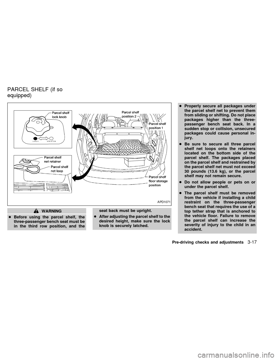
WARNING
cBefore using the parcel shelf, the
three-passenger bench seat must be
in the third row position, and theseat back must be upright.
cAfter adjusting the parcel shelf to the
desired height, make sure the lock
knob is securely latched.cProperly secure all packages under
the parcel shelf net to prevent them
from sliding or shifting. Do not place
packages higher than the three-
passenger bench seat back. In a
sudden stop or collision, unsecured
packages could cause personal in-
jury.
cBe sure to secure all three parcel
shelf net loops onto the retainers
located on the bottom side of the
parcel shelf. The packages placed
on the parcel shelf and restrained by
the parcel shelf net must not exceed
30 pounds (13.6 kg), or the parcel
shelf may not remain secure.
cDo not allow people or pets on or
under the parcel shelf.
cThe parcel shelf must be removed
from the vehicle if installing a child
restraint on the three-passenger
bench seat that requires the use of a
top tether strap that is anchored to
the vehicle floor. Failure to remove
the parcel shelf can increase the
severity of injury to the child in an
accident.
APD1071
PARCEL SHELF (if so
equipped)
Pre-driving checks and adjustments3-17
ZX
Page 133 of 286

The parcel shelf allows for additional stor-
age for packages.
Do not load more than 30 pounds (13.6 kg)
on the parcel shelf. The parcel shelf can be
installed at two different heights and in a
storage position.
To install the parcel shelf:
c
Position the right side of the parcel shelf
in to one of the shelf positions on the right
side luggage compartment trim panel.
cPosition the left side of the parcel shelf
into the matching position (same height)
on the left side luggage compartment trim
panel.
cSlide the parcel shelf lock knob fully to
the left side (latch in green dot position).
cTurn the parcel shelf lock knob clock-
wise until securely locked.
The parcel shelf is also equipped with a
parcel shelf net to keep packages on the
parcel shelf from moving around while the
vehicle is in motion.
The parcel shelf net is permanently at-
tached to the back side of the parcel shelf.
Pull the parcel shelf net over the packagesand attach the three loops to the three
retainers on the bottom side of the parcel
shelf. Make sure the parcel shelf is securely
locked before covering the packages with
the parcel shelf net.
To remove the parcel shelf:
cUnlock the parcel shelf net.
cRemove all packages from the parcel
shelf.
cTurn the parcel shelf lock knob counter
clockwise until loose (maximum two
turns).
cSlide the parcel shelf lock knob fully to
the right side (unlatch in red dot posi-
tion).
cRemove the parcel shelf from the left
side luggage compartment trim panel,
then the right side luggage compartment
trim panel and reposition the parcel shelf
where desired.Put the parcel shelf in the floor storage
position when the parcel shelf is not used or
required.
APD1073
3-18Pre-driving checks and adjustments
ZX
Page 232 of 286
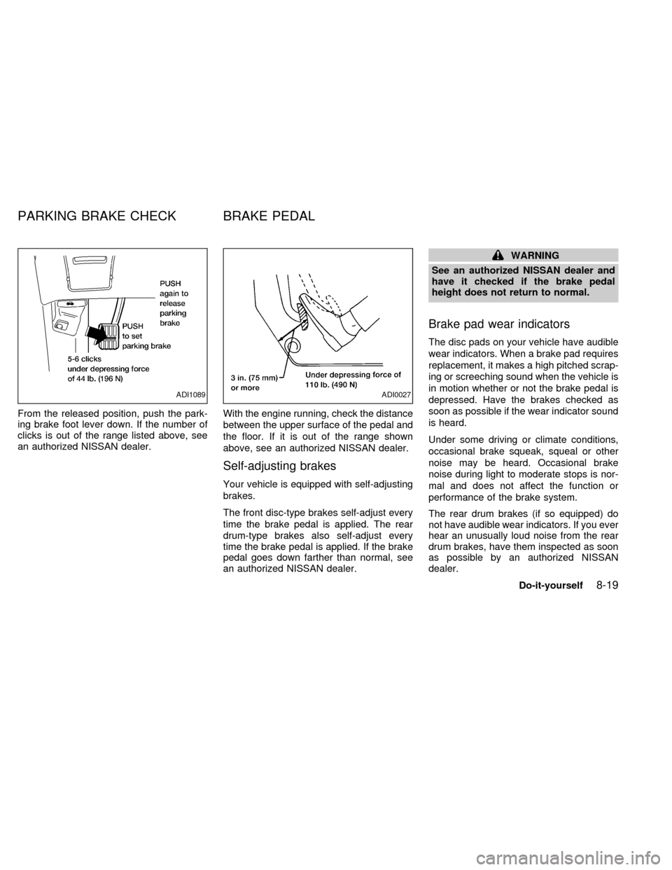
From the released position, push the park-
ing brake foot lever down. If the number of
clicks is out of the range listed above, see
an authorized NISSAN dealer.With the engine running, check the distance
between the upper surface of the pedal and
the floor. If it is out of the range shown
above, see an authorized NISSAN dealer.
Self-adjusting brakes
Your vehicle is equipped with self-adjusting
brakes.
The front disc-type brakes self-adjust every
time the brake pedal is applied. The rear
drum-type brakes also self-adjust every
time the brake pedal is applied. If the brake
pedal goes down farther than normal, see
an authorized NISSAN dealer.
WARNING
See an authorized NISSAN dealer and
have it checked if the brake pedal
height does not return to normal.
Brake pad wear indicators
The disc pads on your vehicle have audible
wear indicators. When a brake pad requires
replacement, it makes a high pitched scrap-
ing or screeching sound when the vehicle is
in motion whether or not the brake pedal is
depressed. Have the brakes checked as
soon as possible if the wear indicator sound
is heard.
Under some driving or climate conditions,
occasional brake squeak, squeal or other
noise may be heard. Occasional brake
noise during light to moderate stops is nor-
mal and does not affect the function or
performance of the brake system.
The rear drum brakes (if so equipped) do
not have audible wear indicators. If you ever
hear an unusually loud noise from the rear
drum brakes, have them inspected as soon
as possible by an authorized NISSAN
dealer.
ADI1089ADI0027
PARKING BRAKE CHECK BRAKE PEDAL
Do-it-yourself8-19
ZX
Page 233 of 286
Proper brake inspection intervals should
be followed.For more information regard-
ing brake inspections, see the appropriate
maintenance schedule information in the
``Maintenance'' section of this manual.Check the brake booster function as fol-
lows:
1. With the engine off, press and release
the brake pedal several times. When
brake pedal movement (distance of
travel) remains the same from one pedal
application to the next, continue on to the
next step.
2. While depressing the brake pedal, start
the engine. The pedal height should drop
a little.
3. With the brake pedal depressed, turn the
engine off. Keep the pedal depressed for
about 30 seconds; the pedal height
should not change.
4. Run the engine for one minute without
depressing the brake pedal, then turn it
off. Depress the brake pedal several
times. The pedal travel distance will de-
crease gradually with each depression
as the vacuum is released from the
booster.
If the brakes do not operate properly, see an
authorized NISSAN dealer.
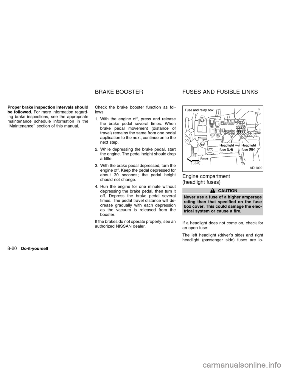
Engine compartment
(headlight fuses)
CAUTION
Never use a fuse of a higher amperage
rating than that specified on the fuse
box cover. This could damage the elec-
trical system or cause a fire.
If a headlight does not come on, check for
an open fuse:
The left headlight (driver's side) and right
headlight (passenger side) fuses are lo-
ADI1090
BRAKE BOOSTER FUSES AND FUSIBLE LINKS
8-20Do-it-yourself
ZX
Page 243 of 286
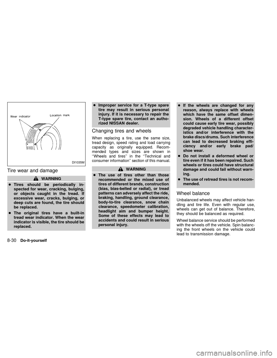
Tire wear and damage
WARNING
cTires should be periodically in-
spected for wear, cracking, bulging,
or objects caught in the tread. If
excessive wear, cracks, bulging, or
deep cuts are found, the tire should
be replaced.
cThe original tires have a built-in
tread wear indicator. When the wear
indicator is visible, the tire should be
replaced.cImproper service for a T-type spare
tire may result in serious personal
injury. If it is necessary to repair the
T-type spare tire, contact an autho-
rized NISSAN dealer.
Changing tires and wheels
When replacing a tire, use the same size,
tread design, speed rating and load carrying
capacity as originally equipped. Recom-
mended types and sizes are shown in
``Wheels and tires'' in the ``Technical and
consumer information'' section of this manual.
WARNING
c
The use of tires other than those
recommended or the mixed use of
tires of different brands, construction
(bias, bias-belted or radial), or tread
patterns can adversely affect the ride,
braking, handling, ground clearance,
body-to-tire clearance, snow chain
clearance, speedometer calibration,
headlight aim and bumper height.
Some of these effects may lead to
accidents and could result in serious
personal injury.cIf the wheels are changed for any
reason, always replace with wheels
which have the same offset dimen-
sion. Wheels of a different offset
could cause early tire wear, possibly
degraded vehicle handling character-
istics and/or interference with the
brake discs/drums. Such interference
can lead to decreased braking effi-
ciency and/or early brake pad/
shoe wear.
cDo not install a deformed wheel or
tire even if it has been repaired. Such
wheels or tires could have structural
damage and could fail without warn-
ing.
cThe use of retread tires is not recom-
mended.
Wheel balance
Unbalanced wheels may affect vehicle han-
dling and tire life. Even with regular use,
wheels can get out of balance. Therefore,
they should be balanced as required.
Wheel balance service should be performed
with the wheels off the vehicle. Spin balanc-
ing the front wheels on the vehicle could
lead to transmission damage.
DI1035M
8-30Do-it-yourself
ZX
Page 265 of 286

Road wheel Steel 5.5JJ ý 15
Aluminum 6JJ ý 15
6.5JJ x 15
6JJx16
Offset in (mm) 1.77 (45)
Tire size Conventional P215/70R15 97 S
Painted cast aluminum P215/70R15 97 S
Machined cast aluminum P225/60R16 97 T
Spare T125/90D16
P215/70R15 97 SOverall length in (mm) 194.8 (4,949)
Overall width in (mm) 74.9 (1,903)
Overall height in (mm) 67.3 (1,710)
Front tread in (mm) 63.4 (1,610)
Rear tread in (mm) 63.4 (1,610)
Wheelbase in (mm) 112.2 (2,850)
Gross vehicle weight
rating lb (kg)
See the ``F.M.V.S.S. certification label''
on the left center pillar. Gross axle weight rating
Front lb (kg)
Rear lb (kg)
WHEEL/TIRE SIZE DIMENSIONS AND WEIGHTS
10-8Technical and consumer information
ZX