key battery NISSAN QUEST 2005 V42 / 3.G User Guide
[x] Cancel search | Manufacturer: NISSAN, Model Year: 2005, Model line: QUEST, Model: NISSAN QUEST 2005 V42 / 3.GPages: 328, PDF Size: 5.75 MB
Page 156 of 328

3. Push the memory switch 1 or 2 fully for at
least 1 second to operate the automatic
drive positioner.
4. Turn the outside mirror control switch to L
(left) .
5. Depress the brake pedal.
6. Move the automatic transmission shift lever
to R (Reverse) .
7. Adjust the mirror to the desired viewing po-
sition for backing up by operating the out-
side mirror control switch.
8. Push the SET switch and, within 5 seconds,
push the memory switch 1 or 2 selected in
step 3 fully for at least 1 second.
cThe indicator light for the pushed memory
switch will come on and stay on for approxi-
mately 5 seconds after pushing the switch.
After the indicator light goes off, the se-
lected mirror position is stored in the se-
lected memory (1 or 2) .
9. Turn the outside mirror control switch to R
(right) . Repeat the above procedure to ad-
just the right mirror position and store in the
selected memory.
cWhen the driver’s seat, accelerator and
brake pedals, and outside mirrors are not in
the memorized position, the outside mirrorwill move with the initial tilt-down angle.
Confirming memory storage
cTurn the ignition ON and push the SET
switch. If the main memory has not been
stored, the indicator light will come on for
approximately 0.5 seconds. When the
memory has stored the position, the indica-
tor light will stay on for approximately 5 sec-
onds.
cIf the battery cable is disconnected, or if the
fuse opens, the memory will be canceled. In
such a case, reset the desired positions
using the following procedures.
1. Open and close the driver’s door more than
two times with the ignition key in the LOCK
position.
2. Reset the desired position using the previ-
ous procedure.
Selecting the memorized position
1. Set the automatic transmission selector le-
ver to the P (Park) position.
2. Turn the ignition ON.
3. Push the memory switch (1 or 2) fully for at
least 1 second.
The driver’s seat, accelerator and brake
pedals, and outside mirrors will move to thememorized position with the indicator light
blinking, and then the light will stay on for
approximately 5 seconds.
ENTRY/EXIT FUNCTION
This system is designed so that the driver’s seat
will automatically move when the automatic
transmission selector lever is in the P (Park)
position. This allows the driver to get into and out
of the driver’s seat more easily.
The driver’s seat will slide backward:
cWhen the key is removed from the ignition
switch.
cWhen the driver’s door is opened with the
key turned to LOCK.
cWhen the key is turned from ACC to LOCK
with the driver’s door open while the auto-
matic transmission selector lever is in the P
(Park) position.
The driver’s seat will return to previous position:
cWhen the key is inserted into the ignition
switch.
cWhen the driver’s door is closed with the key
turned to LOCK.
cWhen the key is turned from ACC to ON
while the automatic transmission selector
lever is in the P (Park) position.
3-26Pre-driving checks and adjustments
ZREVIEW COPYÐ2005 Quest(van)
Owners ManualÐUSA_English(nna)
07/21/04Ðdebbie
X
Page 162 of 328

HOW TO USE “FUEL ECON”
BUTTON
The average fuel consumption (MPG or L/100
km) and the distance to empty (dte — mi or km)
will appear on the screen when the“FUEL
ECON”button is pushed.
Average fuel consumption (MPG or
L/100 km)
The average fuel consumption mode shows the
average fuel consumption since the last reset.
Resetting is done by pressing the“TRIP RE-
SET”or“FUEL ECON”button for more than
approximately 1.5 seconds.The display is updated every 30 seconds. For
approximately the first 30 seconds and 1/3 miles
(500 m) after a reset or connecting the battery
cables, the display will show (----) .
Distance to empty (dte — mile or km)
The distance to empty (dte) mode provides you
with an estimation of the distance that can be
driven before refueling. The dte is constantly be-
ing calculated based on the amount of fuel in the
fuel tank and the actual fuel consumption.
The display is updated every 30 seconds.
When the fuel level is low, the dte display will
change to (*) .
NOTE:
cIf the amount of fuel added while the ignition
switch is OFF is small, the display just before
the ignition switch is turned OFF may con-
tinue to be displayed.
cWhen driving uphill or rounding curves, the
fuel in the tank shifts, which may momentarily
change the display.
CLOCK
The digital clock displays time when the ignition
key is in ACC or ON.
If the power supply is disconnected, the
clock will not indicate the correct time.
Readjust the time.
Adjusting the time
To adjust the time, push the“H”or“M”button
for more than approximately 1.5 seconds. The
time indicator will flash.
Touch the“H”button to adjust the hour.
Touch the“M”button to adjust the minute.
To finish the adjusting, press the“PREV”button
or the screen will return to normal after 10 sec-
onds.
HOW TO USE “E/M” (English/Metric)
BUTTON
You can change the unit as follows using the
“E/M”button.
Unit: US — mile, °F, MPG
Metric — km, °C, L/100 km
LHA0253
4-4Display screen, heater, air conditioner and audio systems
ZREVIEW COPYÐ2005 Quest(van)
Owners ManualÐUSA_English(nna)
07/21/04Ðdebbie
X
Page 166 of 328

When you use this system, make sure the engine
is running.
If you use the system with the engine not
running (ignition ON or ACC) for a long
time, it will use up all the battery power,
and the engine will not start.Reference symbols:
“ENTER”button — This is a button on the con-
trol panel.“Display”key — This is a select key on the
screen. By selecting this key you can proceed to
the next function.
NAMES OF THE COMPONENTS
1.brightness control button (P. 4-17)
2. PREV (previous) button (P. 4-9)
3. Joystick and ENTER push button (P. 4-9)
4. SETTING button (P. 4-12)
5. TRIP drive computer button (P. 4-9)
6. DEST button*
7. ROUTE button*
8. MAP button*
9. GUIDE VOICE button*
10.
zoom out button*
11.
zoom in button*
*For Navigation system control buttons, refer to
the separate Navigation System Owner’s
Manual.
LHA0377
CONTROL PANEL BUTTONS — WITH
NAVIGATION SYSTEM
4-8Display screen, heater, air conditioner and audio systems
ZREVIEW COPYÐ2005 Quest(van)
Owners ManualÐUSA_English(nna)
07/21/04Ðdebbie
X
Page 203 of 328
CAUTION
cThe glass screen on the liquid crystal
display may break if hit with a hard or
sharp object. If the glass breaks, do not
touch the liquid crystalline material,
which contains a small amount of mer-
cury. In case of contact with skin, wash
immediately with soap and water.
cUse a damp, soft cloth when cleaning
the DVD Entertainment System compo-
nents. Do not use solvents or cleaning
solutions.
cDo not attempt to use the system in
extreme temperature conditions [below
-4°F (-20°C) or above 158°F (70°C)].
cTo avoid draining the vehicle battery, do
not operate the system more than 15
minutes without starting the engine.
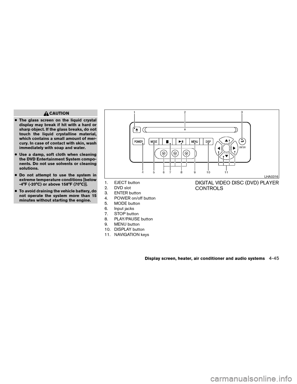
1. EJECT button
2. DVD slot
3. ENTER button
4. POWER on/off button
5. MODE button
6. Input jacks
7. STOP button
8. PLAY/PAUSE button
9. MENU button
10. DISPLAY button
11. NAVIGATION keysDIGITAL VIDEO DISC (DVD) PLAYER
CONTROLS
LHA0316
Display screen, heater, air conditioner and audio systems4-45
ZREVIEW COPYÐ2005 Quest(van)
Owners ManualÐUSA_English(nna)
07/21/04Ðdebbie
X
Page 213 of 328

5 Starting and driving
Precautions when starting and driving................5-2
Exhaust gas (carbon monoxide)..................5-2
Three-way catalyst..............................5-2
Low tire pressure warning system................5-3
Avoiding collision and rollover....................5-4
Drinking alcohol/drugs and driving................5-5
Ignition switch.....................................5-5
Automatic transmission..........................5-5
Key positions..................................5-6
Nissan vehicle immobilizer system (NVIS).........5-6
Before starting the engine..........................5-6
Starting the engine................................5-7
Driving the vehicle.................................5-7
Automatic transmission..........................5-7
Parking brake....................................5-11
Cruise control....................................5-12
Precautions on cruise control...................5-12
Cruise control operations.......................5-12
Break-in schedule................................5-13Increasing fuel economy...........................5-14
Parking/parking on hills............................5-15
Power steering...................................5-15
Brake system....................................5-16
Brake precautions.............................5-16
Anti-lock brake system (ABS)...................5-16
Traction control system (TCS)......................5-18
Vehicle dynamic control (VDC) system
(if so equipped)..................................5-19
Rear sonar system (if so equipped).................5-20
Cold weather driving..............................5-21
Freeing a frozen door lock......................5-21
Anti-freeze....................................5-21
Battery.......................................5-21
Draining of coolant water.......................5-21
Tire equipment................................5-21
Special winter equipment.......................5-22
Driving on snow or ice.........................5-22
ZREVIEW COPYÐ2005 Quest(van)
Owners ManualÐUSA_English(nna)
07/21/04Ðdebbie
X
Page 221 of 328
4. Move the shift selector lever to P (Park) or N
(Neutral) to restart the vehicle (P is pre-
ferred) . Move the shift selector lever to P
(Park) to park the vehicle and turn the igni-
tion key to the LOCK position to remove the
key.
P (Park):
Use this selector position when the vehicle is
parked or when starting the engine. Make sure
the vehicle is completely stopped.The brake
pedal must be depressed to move the se-
lector lever from N (Neutral) or any drive
position to P (Park) .Apply the parking brake.
When parking on a hill, apply the parking brake
first, then move the shift selector lever into the P
(Park) position.
R (Reverse):
CAUTION
Use this position only when the vehicle is
completely stopped.
Use this position to back up. Make sure the
vehicle is completely stopped before selecting
the R (Reverse) position.The brake pedal
must be depressed to move the selector
lever from P (Park) , N (Neutral) or any drive
position to R (Reverse) .N (Neutral):
Neither forward nor reverse gear is engaged. The
engine can be started in this position. You may
shift to N (Neutral) and restart a stalled engine
while the vehicle is moving.
D (Drive):
Use this position for all normal forward driving.
L (Low gear):
Use this position when climbing steep hills slowly
or slow driving through deep snow, sand or mud,
or for maximum engine braking on steep downhill
grades.
Do not shift into the L position at speeds above
65 MPH (105 km/h) . Do not exceed 65 MPH
(105 km/h) in the L position.
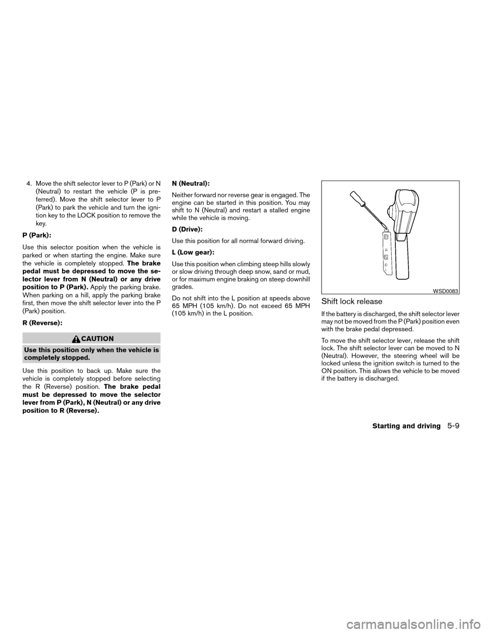
Shift lock release
If the battery is discharged, the shift selector lever
may not be moved from the P (Park) position even
with the brake pedal depressed.
To move the shift selector lever, release the shift
lock. The shift selector lever can be moved to N
(Neutral) . However, the steering wheel will be
locked unless the ignition switch is turned to the
ON position. This allows the vehicle to be moved
if the battery is discharged.
WSD0083
Starting and driving5-9
ZREVIEW COPYÐ2005 Quest(van)
Owners ManualÐUSA_English(nna)
07/21/04Ðdebbie
X
Page 233 of 328

will sound for only three seconds. Once the sys-
tem detects an object approaching, the tone will
sound again.
The RSS automatically turns on when the gear
selector is placed in R (Reverse) and the ignition
is ON. The RSS OFF switch on the instrument
panel allows the driver to turn the RSS on and off.
To turn the RSS off, the ignition must be ON, and
the gear selector in R (Reverse) . An indicator
light on the switch will illuminate when the system
is turned off. If the indicator light illuminates when
the RSS is not turned off, it may indicate a failure
in the RSS.
Keep the RSS sensors (located on the rear
bumper fascia) free from snow, ice and large
accumulations of dirt (do not clean the sensors
with sharp objects) . If the sensors are covered, it
will affect the accuracy of the RSS.FREEING A FROZEN DOOR LOCK
To prevent a door lock from freezing, apply de-
icer through the key hole. If the lock becomes
frozen, heat the key before inserting it into the key
hole.
ANTI-FREEZE
In the winter when it is anticipated that the tem-
perature will drop below 32°F (0°C) , check the
anti-freeze to assure proper winter protection.
For details, see ‘‘Engine cooling system’’ in the
‘‘Maintenance and do-it-yourself’’ section of this
manual.
BATTERY
If the battery is not fully charged during extremely
cold weather conditions, the battery fluid may
freeze and damage the battery. To maintain maxi-
mum efficiency, the battery should be checked
regularly. For details, see ‘‘Battery’’ in the ‘‘Main-
tenance and do-it-yourself’’ section of this
manual.
DRAINING OF COOLANT WATER
If the vehicle is to be left outside without anti-
freeze, drain the cooling system, including the
engine block. Refill before operating the vehicle.For details, see ‘‘Changing engine coolant’’ in the
‘‘Maintenance and do-it-yourself’’ section of this
manual.
TIRE EQUIPMENT
1. SUMMER tires have a tread designed to
provide superior performance on dry pave-
ment. However, the performance of these
tires will be substantially reduced in snowy
and icy conditions. If you operate your ve-
hicle on snowy or icy roads, NISSAN recom-
mends the use of MUD & SNOW or ALL
SEASON TIRES on all four wheels. Please
consult a NISSAN dealer for the tire type,
size, speed rating and availability informa-
tion.
2. For additional traction on icy roads, studded
tires may be used. However, some U.S.
states and Canadian provinces prohibit their
use. Check local, state and provincial laws
before installing studded tires.
Skid and traction capabilities of studded
snow tires on wet or dry surfaces may be
poorer than that of non-studded snow tires.
3. Tire chains may be used.
Use of tire chains may be prohibited accord-
ing to location. Check the local laws before
installing tire chains. When installing tire
chains, make sure they are of proper size for
COLD WEATHER DRIVING
Starting and driving5-21
ZREVIEW COPYÐ2005 Quest(van)
Owners ManualÐUSA_English(nna)
07/21/04Ðdebbie
X
Page 242 of 328
WARNING
Always follow the instructions below.
Failure to do so could result in damage to
the charging system and cause personal
injury.
1. If the booster battery is in another vehicle,
position the two vehicles to bring their bat-
teries near each other.
Do not allow the two vehicles to touch.
2. Apply the parking brake. Shift the transmis-
sion into P (Park) . Switch off all unnecessary
electrical systems (lights, heater, air condi-
tioner, etc.) .3. Remove vent caps on the battery (if so
equipped) . Cover the battery with an old
cloth to reduce explosion hazard.
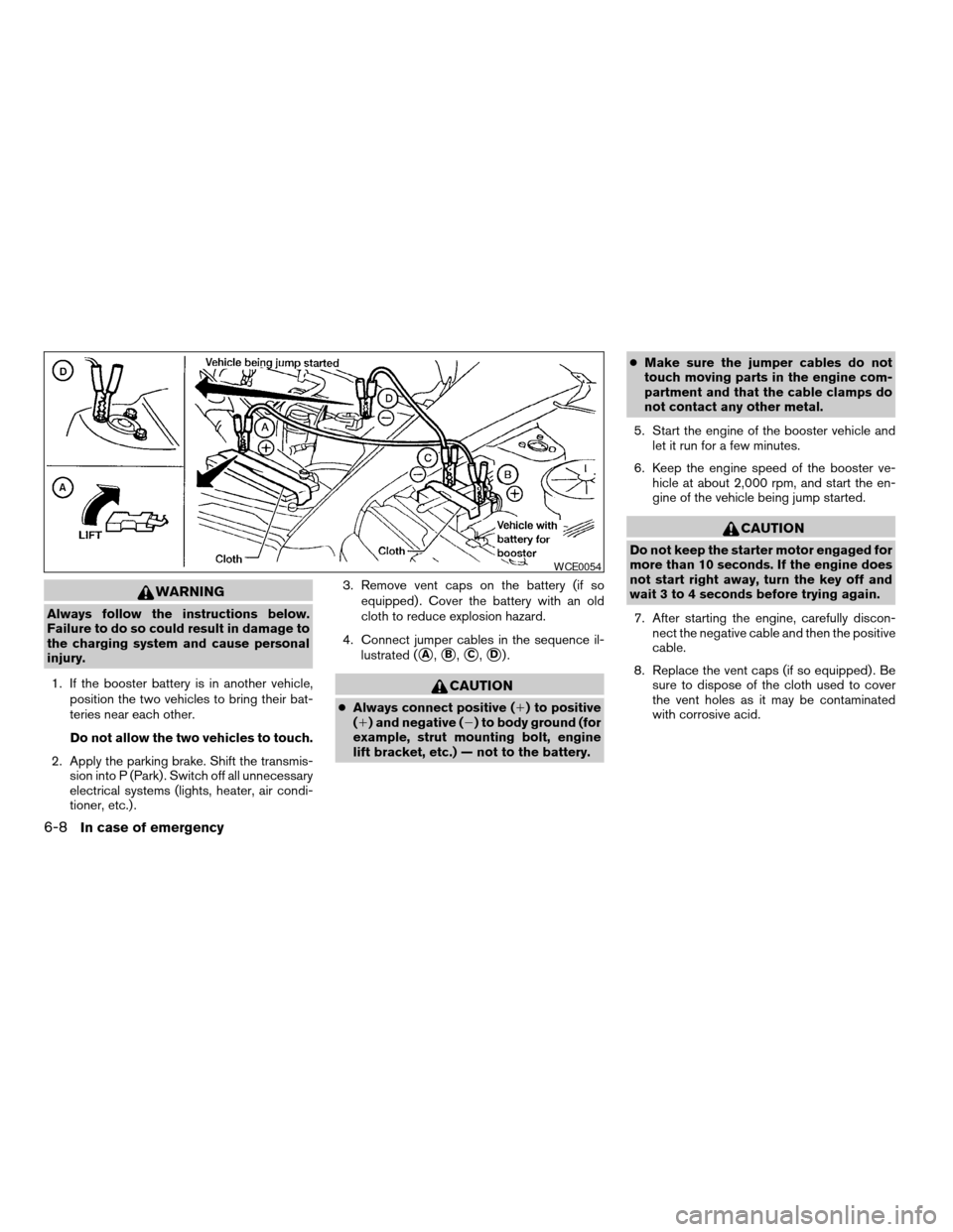
4. Connect jumper cables in the sequence il-
lustrated (
sA,sB,sC,sD).
CAUTION
cAlways connect positive (1) to positive
(1) and negative (2) to body ground (for
example, strut mounting bolt, engine
lift bracket, etc.) — not to the battery.cMake sure the jumper cables do not
touch moving parts in the engine com-
partment and that the cable clamps do
not contact any other metal.
5. Start the engine of the booster vehicle and
let it run for a few minutes.
6. Keep the engine speed of the booster ve-
hicle at about 2,000 rpm, and start the en-
gine of the vehicle being jump started.
CAUTION
Do not keep the starter motor engaged for
more than 10 seconds. If the engine does
not start right away, turn the key off and
wait 3 to 4 seconds before trying again.
7. After starting the engine, carefully discon-
nect the negative cable and then the positive
cable.
8. Replace the vent caps (if so equipped) . Be
sure to dispose of the cloth used to cover
the vent holes as it may be contaminated
with corrosive acid.
WCE0054
6-8In case of emergency
ZREVIEW COPYÐ2005 Quest(van)
Owners ManualÐUSA_English(nna)
07/21/04Ðdebbie
X
Page 253 of 328

8 Maintenance and do-it-yourself
Maintenance requirements..........................8-2
General maintenance..............................8-2
Explanation of general maintenance items.........8-2
Maintenance precautions...........................8-5
Engine compartment check locations................8-6
Engine cooling system.............................8-7
Checking engine coolant level...................8-7
Changing engine coolant........................8-8
Engine oil.........................................8-8
Checking engine oil level........................8-8
Changing engine oil............................8-9
Changing engine oil filter.......................8-10
4-speed automatic transmission fluid...............8-11
Temperature conditions for checking.............8-11
5-speed automatic transmission fluid...............8-12
Power steering fluid...............................8-13
Brake fluid.......................................8-13
Brake fluid....................................8-13
Window washer fluid.............................8-14
Window washer fluid reservoir..................8-14
Battery..........................................8-14
Jump starting.................................8-16
Drive belts.......................................8-16
Spark plugs......................................8-17Replacing spark plugs.........................8-17
Air cleaner.......................................8-17
In-cabin microfilter.............................8-18
Windshield wiper blades..........................8-19
Cleaning.....................................8-19
Replacing....................................8-19
Parking brake and brake pedal.....................8-22
Checking parking brake........................8-22
Checking brake pedal..........................8-22
Brake booster.................................8-23
Fuses...........................................8-23
Engine compartment...........................8-23
Passenger compartment.......................8-24
Keyfob battery replacement........................8-25
Lights...........................................8-26
Headlights....................................8-26
Fog lights (if so equipped)......................8-26
Exterior and interior lights.......................8-27
Wheels and tires.................................8-31
Tire pressure..................................8-31
Tire labeling...................................8-33
Types of tires..................................8-36
Tire chains....................................8-36
Changing wheels and tires.....................8-37
ZREVIEW COPYÐ2005 Quest(van)
Owners ManualÐUSA_English(nna)
07/21/04Ðdebbie
X
Page 257 of 328
When performing any inspection or maintenance
work on your vehicle, always take care to prevent
serious accidental injury to yourself or damage to
the vehicle. The following are general precau-
tions which should be closely observed.
WARNING
cPark the vehicle on a level surface, ap-
ply the parking brake securely and
block the wheels to prevent the vehicle
from moving. Move the shift selector
lever to P (Park) .
cBe sure the ignition key is in the OFF or
LOCK position when performing any
parts replacement or repairs.
cNever leave the engine or automatic
transmission related component har-
nesses disconnected while the ignition
switch is in the ON position.
cNever connect or disconnect the battery
or any transistorized component while
the ignition switch is in the ON position.
c
Your vehicle is equipped with an auto-
matic engine cooling fan. It may come on
at any time without warning, even if the
ignition key is in the OFF position and the
engine is not running. To avoid injury,
always disconnect the negative battery
cable before working near the fan.
cIf you must work with the engine run-
ning, keep your hands, clothing, hair
and tools away from moving fans, belts
and any other moving parts.
cIt is advisable to secure or remove any
loose clothing and remove any jewelry,
such as rings, watches, etc. before
working on your vehicle.
cAlways wear eye protection whenever
you work on your vehicle.
cIf you must run the engine in an en-
closed space such as a garage, be sure
there is proper ventilation for exhaust
gases to escape.
cNever get under the vehicle while it is
supported only by a jack. If it is neces-
sary to work under the vehicle, support
it with safety stands.
cKeep smoking materials, flame and
sparks away from the fuel tank and
battery.
cOn gasoline engine models with the
multiport fuel injection (MFI) system,
the fuel filter or fuel lines should be
serviced by a NISSAN dealer because
the fuel lines are under high pressure
even when the engine is off.CAUTION
cDo not work under the hood while the
engine is hot. Turn the engine off and
wait until it cools down.
cAvoid contact with used engine oil and
coolant. Improperly disposed engine
oil, engine coolant and/or other vehicle
fluids can damage the environment. Al-
ways conform to local regulations for
disposal of vehicle fluid.
This “Maintenance and do-it-yourself” section
gives instructions regarding only those items
which are relatively easy for an owner to perform.
A genuine NISSAN service manual is also avail-
able. See “Owner’s Manual/Service Manual or-
der information” in the “Technical and consumer
information” section of this manual.
You should be aware that incomplete or improper
servicing may result in operating difficulties or
excessive emissions, and could affect warranty
coverage.If in doubt about any servicing,
have it done by a NISSAN dealer.
MAINTENANCE PRECAUTIONS
Maintenance and do-it-yourself8-5
ZREVIEW COPYÐ2005 Quest(van)
Owners ManualÐUSA_English(nna)
07/21/04Ðdebbie
X