clock NISSAN QUEST 2006 V42 / 3.G User Guide
[x] Cancel search | Manufacturer: NISSAN, Model Year: 2006, Model line: QUEST, Model: NISSAN QUEST 2006 V42 / 3.GPages: 352, PDF Size: 6.16 MB
Page 183 of 352

System settings
Language/Unit
The LANGUAGE/UNIT screen will appear when
selecting the“Language/Unit”key and push-
ing the“ENTER”button.
Language: English or French
Unit: US — mile, °F, MPG
Metric — km, °C, L/100 km
You can select the language and unit using the
joystick and“ENTER”button.Clock
Adjusting the time:
Select the“Hours”or“Minutes”key and move
the joystick to the right or left to adjust the time.
The time will change step by step.Setting daylight savings time:
Use the“Daylight Saving Time”key to adjust
the clock to daylight savings time.
ON: The displayed time advances by 1 hour.
OFF: The current time is displayed.
LHA0561LHA0562LHA0566
Display screen, heater, air conditioner and audio systems4-23
ZREVIEW COPYÐ2006 Quest(van)
Owners ManualÐUSA_English(nna)
05/27/05Ðtbrooks
X
Page 184 of 352
![NISSAN QUEST 2006 V42 / 3.G User Guide Adjusting the time to the GPS:
Select the“Auto Adjust”key.
The time will be reset to the GPS time.Selecting the time zone:
1. Select the“Select Time Zone”key.
The [TIME ZONE] screen will appea NISSAN QUEST 2006 V42 / 3.G User Guide Adjusting the time to the GPS:
Select the“Auto Adjust”key.
The time will be reset to the GPS time.Selecting the time zone:
1. Select the“Select Time Zone”key.
The [TIME ZONE] screen will appea](/img/5/711/w960_711-183.png)
Adjusting the time to the GPS:
Select the“Auto Adjust”key.
The time will be reset to the GPS time.Selecting the time zone:
1. Select the“Select Time Zone”key.
The [TIME ZONE] screen will appear.2. Select one of the following zones depending
on the current location.
cPacific zone
cMountain zone
cCentral zone
cEastern zone
cAtlantic zone
cNewfoundland zone
After selection, the [CLOCK SETTINGS] screen
will appear.
LHA0567LHA0568LHA0563
4-24Display screen, heater, air conditioner and audio systems
ZREVIEW COPYÐ2006 Quest(van)
Owners ManualÐUSA_English(nna)
05/27/05Ðtbrooks
X
Page 232 of 352
1. Move the shift selector lever into the P (Park)
position.
2. Turn the ignition key slightly toward the ON
position.
3. Turn the key to the LOCK position.
4. Remove the key.
The shift selector lever is designed so it cannot
moved out of P (Park) and into any of the other
gear positions if the ignition key is turned to OFF
position or if the key is removed from the switch.
The shift selector lever can be moved if the
ignition switch is in the ON position and the
foot brake pedal is depressed.
There is an OFF position between the
LOCK and ACC positions. The OFF position
is indicated by a “1” on the key cylinder.
When the ignition is in the OFF position,
the steering wheel is not locked.
In order for the steering wheel to be locked, it
must be turned about 1/8 of a turn clockwise
from the straight up position.
To lock the steering wheel, turn the key to
the LOCK position. Remove the key. To
unlock the steering wheel, insert the key
and turn it gently while rotating the steer-
ing wheel slightly right and left.WARNING
Never remove or turn the key to the LOCK
position while driving. The steering wheel
will lock. This may cause the driver to lose
control of the vehicle and could result in
serious vehicle damage or personal injury.
KEY POSITIONS
LOCK: Normal parking position (0)
OFF: (Not used) (1)
ACC: (Accessories) (2)
This position activates electrical accessories
such as the radio when the engine is not running.
ON: Normal operating position (3)
This position turns on the ignition system and the
electrical accessories.
START: (4)
This position starts the engine. As soon as the
engine has started, release the key. It automati-
cally returns to the ON position.
NISSAN VEHICLE IMMOBILIZER
SYSTEM
The NISSAN Vehicle Immobilizer System will not
allow the engine to start without the use of the
registered key.
If the engine fails to start using a registered key
(for example, when interference is caused by
another registered key, an automated toll road
device or automatic payment device on the key
ring) , restart the engine using the following pro-
cedures:
1. Leave the ignition switch in the ON position
for approximately 5 seconds.
2. Turn the ignition switch to the OFF or LOCK
position, and wait approximately 10 sec-
onds.
3. Repeat steps 1 and 2.
4. Restart the engine while holding the device
(which may have caused the interference)
separate from the registered key.
If the no start condition re-occurs, NISSAN rec-
ommends placing the registered key on a sepa-
rate key ring to avoid interference from other
devices.
5-8Starting and driving
ZREVIEW COPYÐ2006 Quest(van)
Owners ManualÐUSA_English(nna)
05/27/05Ðtbrooks
X
Page 233 of 352
cMake sure the area around the vehicle is
clear.
cCheck fluid levels such as engine oil, cool-
ant, brake fluid, and window washer fluid as
frequently as possible, or at least whenever
you refuel.
cCheck that all windows and lights are clean.
cVisually inspect tires for their appearance
and condition. Also check tires for proper
inflation.
cLock all doors.
cPosition seat and adjust head restraints.
cAdjust inside and outside mirrors.
cFasten seat belts and ask all passengers to
do likewise.
cCheck the operation of warning lights when
the key is turned to the ON (3) position. See
“Warning/indicator lights and audible re-
minders” in the “Instruments and controls”
section of this manual.1. Apply the parking brake.
2. Move the shift selector lever to P (Park) or N
(Neutral) . P (Park) is recommended.
The shift selector lever cannot be
moved out of P (Park) and into any of
the other gear positions if the ignition
key is turned to the OFF position or if
the key is removed from the ignition
switch.
The starter is designed not to operate if
the shift selector lever is in any of the
driving positions.
3. Crank the enginewith your foot off the
accelerator pedalby turning the ignition
key to START. Release the key when the
engine starts. If the engine starts, but fails to
run, repeat the above procedure.
cIf the engine is very hard to start in ex-
tremely cold weather or when restarting,
depress the accelerator pedal a little (ap-
proximately 1/3 to the floor) and hold it
and then crank the engine. Release the
key and the accelerator pedal when the
engine starts.
cIf the engine is very hard to start because
it is flooded, depress the accelerator
pedal all the way to the floor and hold it.
Crank the engine for 5-6 seconds. Aftercranking the engine, release the accel-
erator pedal. Crank the enginewith your
foot off the accelerator pedalby turn-
ing the ignition key to START. Release the
key when the engine starts. If the engine
starts, but fails to run, repeat the above
procedure.
CAUTION
Do not operate the starter for more than
15 seconds at a time. If the engine does
not start, turn the key off and wait 10
seconds before cranking again, otherwise
the starter could be damaged.
4. Allow the engine to idle for at least 30 sec-
onds after starting. Do not race the engine
while warming it up. Drive at moderate
speed for a short distance first, especially in
cold weather.
In cold weather, keep the engine running for
a minimum of 2–3 minutes before shutting it
off. Starting and stopping the engine over a
short period of time may make the vehicle
more difficult to start.
BEFORE STARTING THE ENGINE STARTING THE ENGINE
Starting and driving5-9
ZREVIEW COPYÐ2006 Quest(van)
Owners ManualÐUSA_English(nna)
05/27/05Ðtbrooks
X
Page 254 of 352
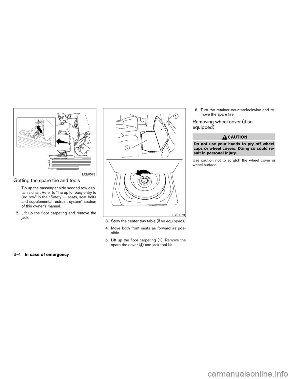
Getting the spare tire and tools
1. Tip up the passenger side second row cap-
tain’s chair. Refer to “Tip up for easy entry to
3rd row” in the “Safety — seats, seat belts
and supplemental restraint system” section
of this owner’s manual.
2. Lift up the floor carpeting and remove the
jack.
3. Stow the center tray table (if so equipped) .
4. Move both front seats as forward as pos-
sible.
5. Lift up the floor carpeting
s1. Remove the
spare tire cover
s2and jack tool kit.6. Turn the retainer counterclockwise and re-
move the spare tire.
Removing wheel cover (if so
equipped)
CAUTION
Do not use your hands to pry off wheel
caps or wheel covers. Doing so could re-
sult in personal injury.
Use caution not to scratch the wheel cover or
wheel surface.
LCE0078
LCE0079
6-4In case of emergency
ZREVIEW COPYÐ2006 Quest(van)
Owners ManualÐUSA_English(nna)
05/27/05Ðtbrooks
X
Page 256 of 352

Always refer to the proper illustrations for the
correct placement and jack-up points for your
specific vehicle model and jack type.
Carefully read the caution label attached to
the jack body and the following instruc-
tions.
1. Loosen each wheel nut one or two turns by
turning counterclockwise with the wheel nut
wrench.Do not remove the wheel nuts
until the tire is off the ground.2. Place the jack directly under the jack-up
point as illustrated so the top of the jack
contacts the vehicle at the jack-up point.
Align the jack head between the two
notches in the front or the rear as shown.
Also fit the groove of the jack head between
the notches as shown.
The jack should be used on firm and
level ground.
3. To lift the vehicle, securely hold the jack lever
and rod with both hands. Carefully raise the
vehicle until the tire clears the ground. Re-
move the wheel nuts, and then remove the
tire.Installing the spare tire
The spare tire is designed for emergency
use. See specific instructions under the
heading “Wheels and tires” in the “Mainte-
nance and do-it-yourself” section of this
manual.
1. Clean any mud or dirt from the surface be-
tween the wheel and hub.
2. Carefully put the spare tire on and tighten
the wheel nuts finger tight.
3. With the wheel nut wrench, tighten wheel
nuts alternately and evenly as illustrated until
they are tight.
WCE0081WCE0056
6-6In case of emergency
ZREVIEW COPYÐ2006 Quest(van)
Owners ManualÐUSA_English(nna)
05/27/05Ðtbrooks
X
Page 279 of 352
CAUTION
Oil level should be checked regularly. Op-
erating the engine with an insufficient
amount of oil can damage the engine, and
such damage is not covered by warranty.
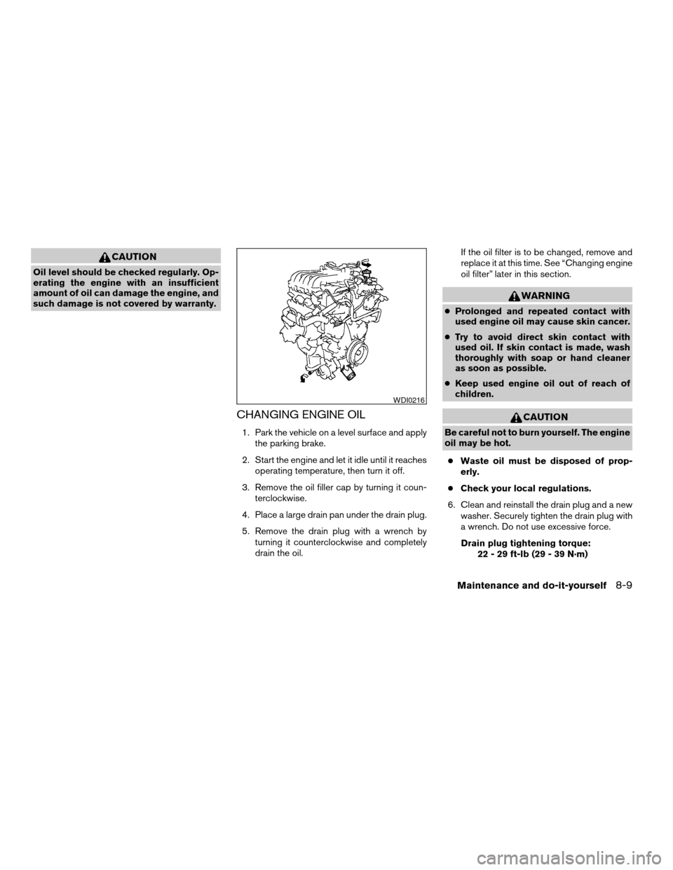
CHANGING ENGINE OIL
1. Park the vehicle on a level surface and apply
the parking brake.
2. Start the engine and let it idle until it reaches
operating temperature, then turn it off.
3. Remove the oil filler cap by turning it coun-
terclockwise.
4. Place a large drain pan under the drain plug.
5. Remove the drain plug with a wrench by
turning it counterclockwise and completely
drain the oil.If the oil filter is to be changed, remove and
replace it at this time. See “Changing engine
oil filter” later in this section.
WARNING
cProlonged and repeated contact with
used engine oil may cause skin cancer.
cTry to avoid direct skin contact with
used oil. If skin contact is made, wash
thoroughly with soap or hand cleaner
as soon as possible.
cKeep used engine oil out of reach of
children.
CAUTION
Be careful not to burn yourself. The engine
oil may be hot.
cWaste oil must be disposed of prop-
erly.
cCheck your local regulations.
6. Clean and reinstall the drain plug and a new
washer. Securely tighten the drain plug with
a wrench. Do not use excessive force.
Drain plug tightening torque:
22 - 29 ft-lb (29 - 39 N·m)
WDI0216
Maintenance and do-it-yourself8-9
ZREVIEW COPYÐ2006 Quest(van)
Owners ManualÐUSA_English(nna)
05/27/05Ðtbrooks
X
Page 280 of 352
7. Refill engine with recommended oil through
the oil filler opening, then install the oil filler
cap securely.
See “Capacities and recommended
fuel/lubricants” in the “Technical and con-
sumer information” section of this manual for
drain and refill capacity.
The drain and refill capacity depends on the
oil temperature and drain time. Use these
specifications for reference only. Always use
the dipstick to determine when the proper
amount of oil is in the engine.
8. Start the engine. Check for leakage around
the drain plug and oil filter. Correct as re-
quired.
9. Turn the engine off and wait more than 10
minutes. Check the oil level with the dipstick.
Add engine oil if necessary.
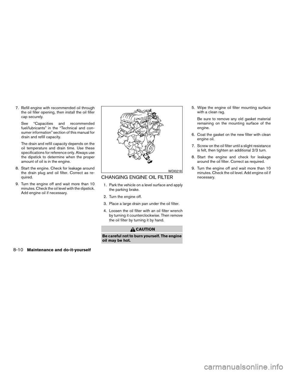
CHANGING ENGINE OIL FILTER
1. Park the vehicle on a level surface and apply
the parking brake.
2. Turn the engine off.
3. Place a large drain pan under the oil filter.
4. Loosen the oil filter with an oil filter wrench
by turning it counterclockwise. Then remove
the oil filter by turning it by hand.
CAUTION
Be careful not to burn yourself. The engine
oil may be hot.5. Wipe the engine oil filter mounting surface
with a clean rag.
Be sure to remove any old gasket material
remaining on the mounting surface of the
engine.
6. Coat the gasket on the new filter with clean
engine oil.
7. Screw on the oil filter until a slight resistance
is felt, then tighten an additional 2/3 turn.
8. Start the engine and check for leakage
around the oil filter. Correct as required.
9. Turn the engine off and wait more than 10
minutes. Check the oil level. Add engine oil if
necessary.
WDI0218
8-10Maintenance and do-it-yourself
ZREVIEW COPYÐ2006 Quest(van)
Owners ManualÐUSA_English(nna)
05/27/05Ðtbrooks
X
Page 297 of 352
cDo not leave the bulb out of the fog light
for a long period of time as dust, mois-
ture and smoke may enter the fog light
body and affect the performance of the
fog light.
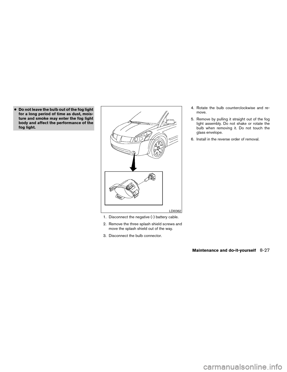
1. Disconnect the negative (-) battery cable.
2. Remove the three splash shield screws and
move the splash shield out of the way.
3. Disconnect the bulb connector.4. Rotate the bulb counterclockwise and re-
move.
5. Remove by pulling it straight out of the fog
light assembly. Do not shake or rotate the
bulb when removing it. Do not touch the
glass envelope.
6. Install in the reverse order of removal.
LDI0362
Maintenance and do-it-yourself8-27
ZREVIEW COPYÐ2006 Quest(van)
Owners ManualÐUSA_English(nna)
05/27/05Ðtbrooks
X
Page 340 of 352

Child restraints.......1-17, 1-18, 1-25, 1-37
Precautions on child restraints . . .1-25, 1-44
Top tether strap anchor point locations . .1-39
Child safety sliding door lock..........3-9
Chimes, audible reminders...........2-14
Cleaning exterior and interior..........7-2
Clock
(models with navigation system) . .4-14, 4-23
(models without navigation system).....4-4
Clock set
Control panel buttons.....4-4, 4-14, 4-23
C.M.V.S.S. certification label..........9-10
Cold weather driving..............5-23
Compact disc (CD) player...........4-47
Control panel buttons
With navigation system........4-8, 4-16
Without navigation system..........4-2
Controls
Audio controls (steering wheel)......4-51
Heater and air conditioner
controls................4-28, 4-37
Rear audio controls.............4-53
Rear seat air conditioner..........4-40
Coolant
Capacities and recommended
fuel/lubricants.................9-2
Changing engine coolant..........8-8
Checking engine coolant level........8-7
Engine coolant temperature gauge.....2-5
Cornering light.................2-23
Corrosion protection...............7-5
Cruise control..................5-14
Cup holders...............2-34, 2-36
Curtain side-impact air bag system
(See supplemental side air bag and curtain
side-impact air bag system)..........1-60D
Daytime running light system
(Canada only)..................2-21
Defroster switch
Rear window and outside mirror defroster
switch....................2-18
Digital video disc DVD.............4-54
Dimensions and weights.............9-8
Display controls
(see control panel buttons).....4-2, 4-8, 4-16
Door locks....................3-3
Door open warning light.............2-8
Drive belts....................8-16
Drive positioner, Automatic...........3-24
Driving
Cold weather driving............5-23
Driving with automatic transmission. . . .5-10
Precautions when starting and driving . . .5-2
DVD entertainment system...........4-54
E
Economy - fuel.................5-16
Emission control information label.......9-10
Emission control system warranty.......9-20
Engine
Before starting the engine..........5-9
Capacities and recommended
fuel/lubricants.................9-2
Changing engine coolant..........8-8
Changing engine oil.............8-9
Changing engine oil filter..........8-10
Checking engine coolant level........8-7Checking engine oil level..........8-8
Engine compartment check locations. . . .8-7
Engine coolant temperature gauge.....2-5
Engine cooling system............8-7
Engine oil...................8-8
Engine oil and oil filter recommendation . .9-5
Engine oil pressure warning light......2-8
Engine oil viscosity..............9-5
Engine serial number............9-10
Engine specifications.............9-7
Starting the engine..............5-9
English/Metric button.......4-4, 4-14, 4-23
Control panel buttons.....4-4, 4-14, 4-23
ENTER button.........4-2, 4-3, 4-8, 4-16
Enter button
Control panel buttons . . .4-2, 4-3, 4-8, 4-16
Event data recorders..............9-22
Exhaust gas (Carbon monoxide)........5-2
Eyeglass case..................2-31
F
Flashers
(See hazard warning flasher switch)......2-23
Flat tire......................6-2
Floor mat positioning aid.............7-4
Fluid
Automatic transmission fluid (ATF). . . .8-11
Brake fluid..................8-13
Capacities and recommended
fuel/lubricants.................9-2
Engine coolant................8-7
Engine oil...................8-8
Power steering fluid.............8-13
Window washer fluid............8-14
10-2
ZREVIEW COPYÐ2006 Quest(van)
Owners ManualÐUSA_English(nna)
05/27/05Ðtbrooks
X