mirror NISSAN QUEST 2008 V42 / 3.G Owners Manual
[x] Cancel search | Manufacturer: NISSAN, Model Year: 2008, Model line: QUEST, Model: NISSAN QUEST 2008 V42 / 3.GPages: 376, PDF Size: 5.21 MB
Page 9 of 376

1. Engine hood (P. 3-14)
2. Headlight and turn signal switch
(P. 2-18)
3. Replacing bulbs (P. 8-27)
4. Windshield wiper and washer switch
(P. 2-16)
5. Windshield (P. 8-17)
6. Power windows (P. 2-36)
7. Door locks, keyfob, keys
(P. 3-3, 3-9, 3-2)
8. Mirrors (P. 3-23)
9. Tire pressure (P. 9-11)
10. Flat tire (P. 6-2)
11. Tire chains (P. 8-37)
12. Fog light switch (P. 2-22)
13. Tie down/towing hooks (P. 6-12)
See the page number indicated in paren-
theses for operating details.
LII0074
EXTERIOR FRONT
Illustrated table of contents0-3
ZREVIEW COPYÐ2008 Quest(van)
Owners ManualÐUSA_English(nna)
06/29/07Ðdebbie
X
Page 84 of 376

2 Instruments and controls
Instrument panel...................................2-2
Meters and gauges................................2-3
Speedometer and odometer.....................2-4
Tachometer....................................2-5
Engine coolant temperature gauge...............2-5
Fuel gauge....................................2-6
Warning/indicator lights and audible reminders.......2-7
Checking bulbs................................2-7
Warning lights.................................2-8
Indicator lights................................2-11
Audible reminders.............................2-13
Security systems.................................2-14
Vehicle security system.........................2-14
NISSAN vehicle immobilizer system.............2-15
Windshield wiper and washer switch...............2-16
Switch operation..............................2-16
Rear window wiper and washer switch..............2-17
Rear window and outside mirror (if so equipped)
defroster switch..................................2-18
Headlight and turn signal switch....................2-18
Headlight control switch........................2-18
Daytime running light system (Canada only)......2-20
Instrument brightness control...................2-21Turn signal switch.............................2-22
Fog light switch (if so equipped)................2-22
Cornering light................................2-23
Hazard warning flasher switch.....................2-23
Horn............................................2-24
Heated seat (if so equipped).......................2-24
Traction Control System (TCS) off switch
(if so equipped)..................................2-25
Vehicle Dynamic Control (VDC) off switch
(if so equipped)..................................2-25
Rear sonar system off switch (if so equipped)........2-25
Power outlet.....................................2-26
Storage.........................................2-27
Sunglasses holder.............................2-27
Instrument panel storage.......................2-27
Console box (if so equipped)...................2-28
Center tray table (if so equipped)................2-29
Glove box....................................2-30
Map pockets..................................2-30
Seatback pockets.............................2-31
Grocery hooks................................2-31
Cargo net (if so equipped)......................2-31
Overhead console.............................2-32
ZREVIEW COPYÐ2008 Quest(van)
Owners ManualÐUSA_English(nna)
06/29/07Ðdebbie
X
Page 102 of 376

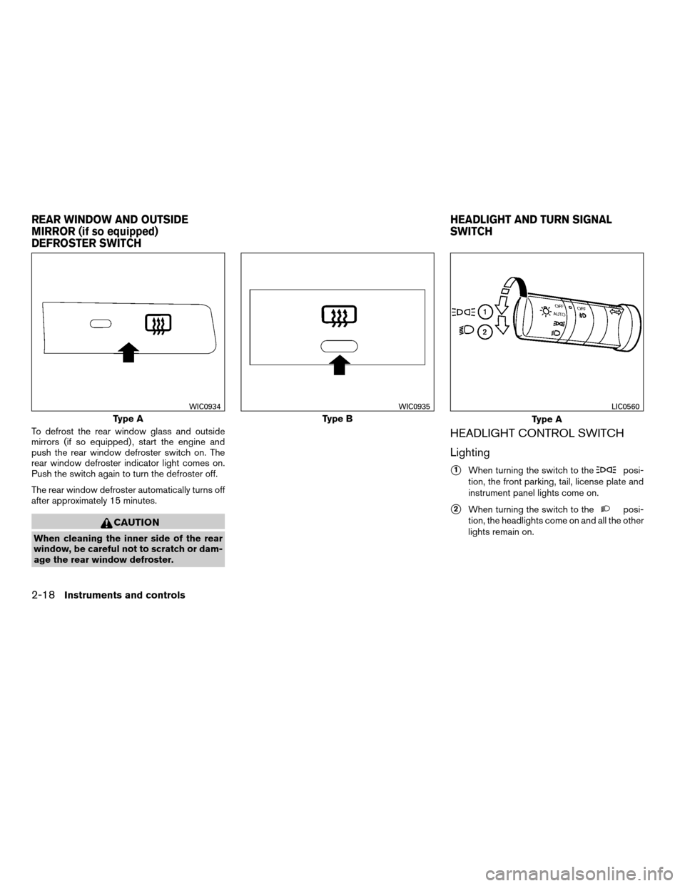
To defrost the rear window glass and outside
mirrors (if so equipped) , start the engine and
push the rear window defroster switch on. The
rear window defroster indicator light comes on.
Push the switch again to turn the defroster off.
The rear window defroster automatically turns off
after approximately 15 minutes.
CAUTION
When cleaning the inner side of the rear
window, be careful not to scratch or dam-
age the rear window defroster.
HEADLIGHT CONTROL SWITCH
Lighting
s1When turning the switch to theposi-
tion, the front parking, tail, license plate and
instrument panel lights come on.
s2When turning the switch to theposi-
tion, the headlights come on and all the other
lights remain on.
Type A
WIC0934
Type B
WIC0935
Type A
LIC0560
REAR WINDOW AND OUTSIDE
MIRROR (if so equipped)
DEFROSTER SWITCHHEADLIGHT AND TURN SIGNAL
SWITCH
2-18Instruments and controls
ZREVIEW COPYÐ2008 Quest(van)
Owners ManualÐUSA_English(nna)
06/29/07Ðdebbie
X
Page 133 of 376

3 Pre-driving checks and adjustments
Keys .............................................3-2
NISSAN vehicle immobilizer system keys..........3-2
Doors............................................3-3
Locking with key................................3-3
Locking with inside lock knob....................3-4
Locking with power door lock switch.............3-5
Operating the manual sliding door
(if so equipped)................................3-5
Using the main ON/OFF switch for the
power sliding door (if so equipped)...............3-6
Operating the power sliding door
(if so equipped)................................3-6
Child safety sliding door lock....................3-9
Remote keyless entry system.......................3-9
How to use remote keyless entry system.........3-10
Hood...........................................3-14
Lift gate.........................................3-14
Operating the manual lift gate...................3-15
Using the main ON/OFF switch for the
power lift gate (if so equipped)..................3-15Operating the power lift gate
(if so equipped)...............................3-16
Lift gate release...............................3-18
Fuel-filler door...................................3-19
Opener operation..............................3-19
Fuel-filler cap.................................3-19
Steering wheel...................................3-21
Tilt operation..................................3-21
Pedal position adjustment (if so equipped)..........3-21
Sun visors.......................................3-22
Vanity mirrors.................................3-22
Mirrors..........................................3-23
Rearview mirror (if so equipped).................3-23
Automatic anti-glare rearview mirror
(if so equipped)...............................3-23
Outside mirrors...............................3-24
Automatic drive positioner (if so equipped)..........3-25
Memory storage function.......................3-26
Entry/exit function.............................3-27
System operation..............................3-27
ZREVIEW COPYÐ2008 Quest(van)
Owners ManualÐUSA_English(nna)
06/29/07Ðdebbie
X
Page 154 of 376

s1To block glare from the front, swing down the
main sun visor.
s2To block glare from the side, remove the
main sun visor from the center mount and
swing the visor to the side.
s3Slide the sun visor in or out as needed.
VANITY MIRRORS
To access the vanity mirror, pull the sun visor
down and flip open the mirror cover. The vanity
mirror will illuminate when the mirror cover is
open.
WPD0344
WPD0345
SUN VISORS
3-22Pre-driving checks and adjustments
ZREVIEW COPYÐ2008 Quest(van)
Owners ManualÐUSA_English(nna)
06/29/07Ðdebbie
X
Page 155 of 376

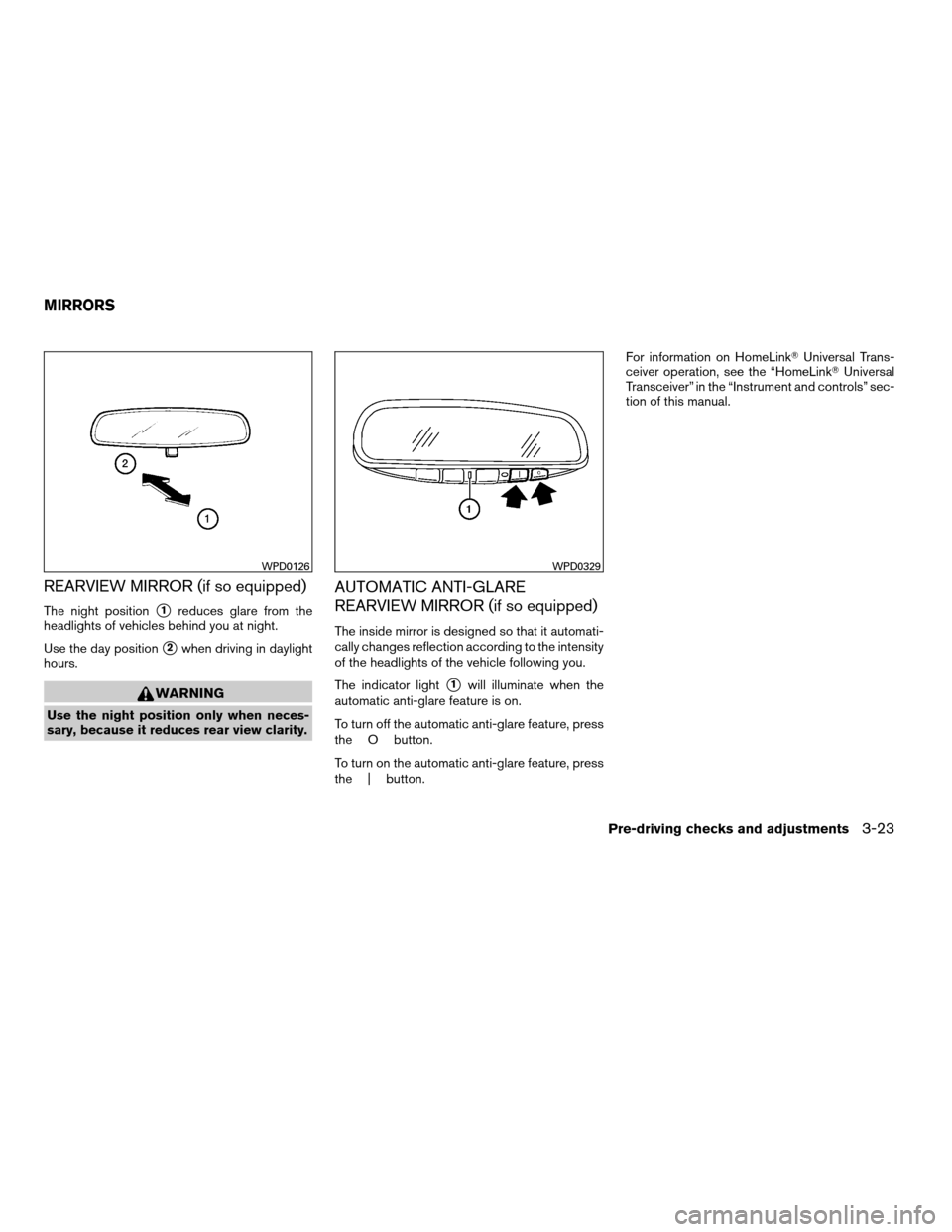
REARVIEW MIRROR (if so equipped)
The night positions1reduces glare from the
headlights of vehicles behind you at night.
Use the day position
s2when driving in daylight
hours.
WARNING
Use the night position only when neces-
sary, because it reduces rear view clarity.
AUTOMATIC ANTI-GLARE
REARVIEW MIRROR (if so equipped)
The inside mirror is designed so that it automati-
cally changes reflection according to the intensity
of the headlights of the vehicle following you.
The indicator light
s1will illuminate when the
automatic anti-glare feature is on.
To turn off the automatic anti-glare feature, press
the O button.
To turn on the automatic anti-glare feature, press
the | button.For information on HomeLinkTUniversal Trans-
ceiver operation, see the “HomeLinkTUniversal
Transceiver” in the “Instrument and controls” sec-
tion of this manual.
WPD0126WPD0329
MIRRORS
Pre-driving checks and adjustments3-23
ZREVIEW COPYÐ2008 Quest(van)
Owners ManualÐUSA_English(nna)
06/29/07Ðdebbie
X
Page 156 of 376

OUTSIDE MIRRORS
WARNING
Objects viewed in the outside mirror on
the passenger side are closer than they
appear. Be careful when moving to the
right. Using only this mirror could cause
an accident. Use the inside mirror or
glance over your shoulder to properly
judge distances to other objects.
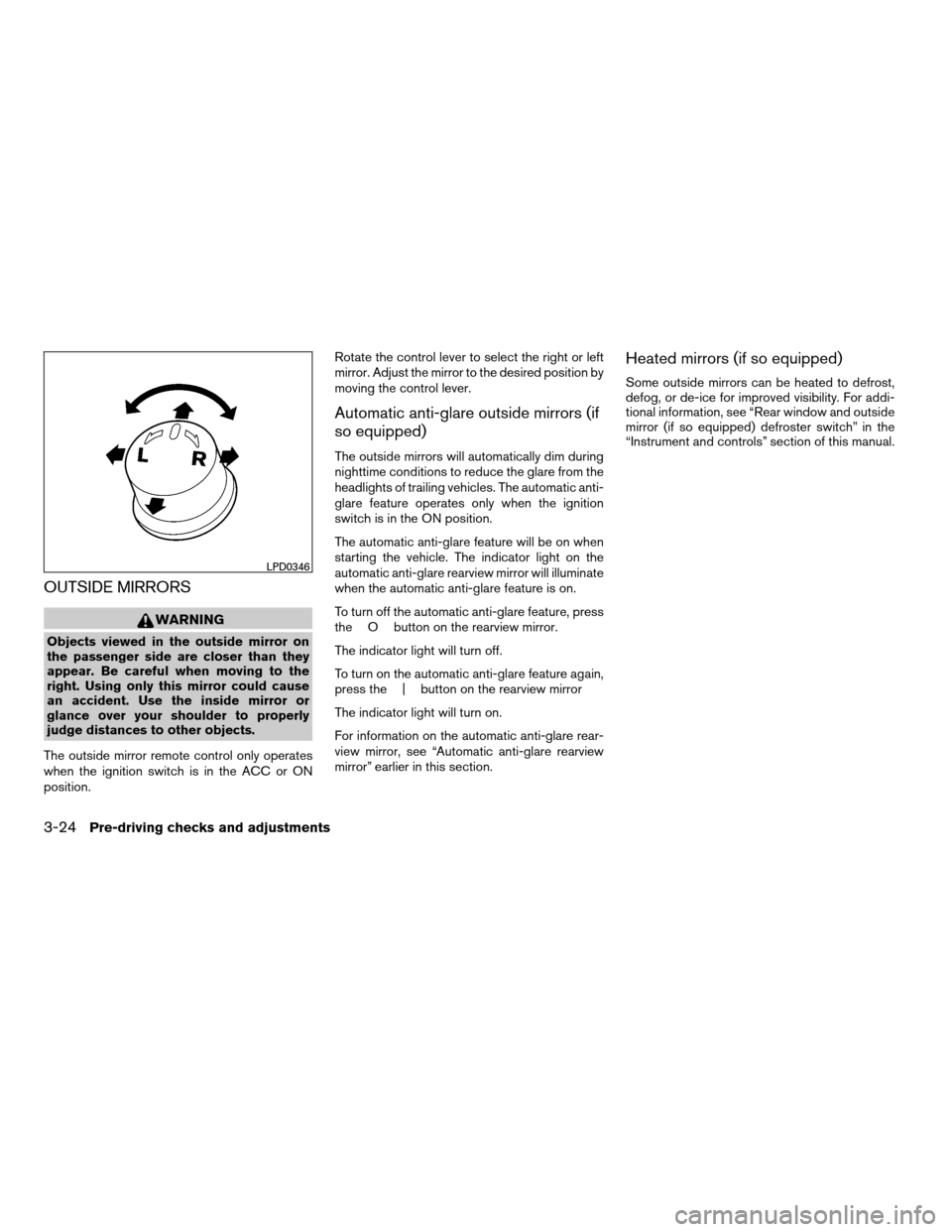
The outside mirror remote control only operates
when the ignition switch is in the ACC or ON
position.Rotate the control lever to select the right or left
mirror. Adjust the mirror to the desired position by
moving the control lever.
Automatic anti-glare outside mirrors (if
so equipped)
The outside mirrors will automatically dim during
nighttime conditions to reduce the glare from the
headlights of trailing vehicles. The automatic anti-
glare feature operates only when the ignition
switch is in the ON position.
The automatic anti-glare feature will be on when
starting the vehicle. The indicator light on the
automatic anti-glare rearview mirror will illuminate
when the automatic anti-glare feature is on.
To turn off the automatic anti-glare feature, press
the O button on the rearview mirror.
The indicator light will turn off.
To turn on the automatic anti-glare feature again,
press the | button on the rearview mirror
The indicator light will turn on.
For information on the automatic anti-glare rear-
view mirror, see “Automatic anti-glare rearview
mirror” earlier in this section.
Heated mirrors (if so equipped)
Some outside mirrors can be heated to defrost,
defog, or de-ice for improved visibility. For addi-
tional information, see “Rear window and outside
mirror (if so equipped) defroster switch” in the
“Instrument and controls” section of this manual.
LPD0346
3-24Pre-driving checks and adjustments
ZREVIEW COPYÐ2008 Quest(van)
Owners ManualÐUSA_English(nna)
06/29/07Ðdebbie
X
Page 157 of 376

Foldable outside mirrors
Push the mirrors backward to fold them.
Reverse tilt-down feature (if so
equipped)
The reverse tilt-down feature will turn the se-
lected outside mirror surface downward to pro-
vide better rear visibility close to the vehicle.
When the ignition switch is in the ON position,
turn the outside mirror control switch to the left or
right position. Only one mirror can be selected at
a time.Move the shift selector lever to R (Reverse) . The
selected mirror will turn downward.
The selected mirror surface will return to its origi-
nal position when any of the following have oc-
curred:
cThe shift selector lever is moved to any po-
sition other than R (Reverse) .
cThe outside mirror control switch is set to the
N (Neutral) position.
cThe ignition switch is turned OFF.
NOTE:
If the outside mirror control switch is in the
neutral position, neither mirror will turn
downward when the shift selector lever is
moved to R (Reverse) .
For more information regarding this feature, refer
to “Automatic drive positioner” later in this sec-
tion.The automatic drive positioner system has two
features:
cMemory storage function
cEntry/exit function
MPA0008
AUTOMATIC DRIVE POSITIONER (if
so equipped)
Pre-driving checks and adjustments3-25
ZREVIEW COPYÐ2008 Quest(van)
Owners ManualÐUSA_English(nna)
06/29/07Ðdebbie
X
Page 158 of 376

MEMORY STORAGE FUNCTION
Two positions for the driver’s seat, accelerator
and brake pedals, and outside mirrors can be
stored in the automatic drive positioner memory.
Follow these procedures to use the memory sys-
tem.
1. Set the automatic transmission selector le-
ver to the P (Park) position.
2. Turn the ignition ON.3. Adjust the driver’s seat, accelerator and
brake pedals, and outside mirrors to the
desired positions by manually operating
each adjusting switch. For additional infor-
mation, see “Seats” in the “Safety—Seats,
seat belts and supplemental restraint sys-
tem” section and “Pedal position adjust-
ment” and “Outside mirrors” earlier in this
section.
During this step, do not turn the ignition to
any position other than ON.
4. Push the SET switch and, within 5 seconds,
push the memory switch (1 or 2) fully for at
least 1 second.
The indicator light for the pushed memory
switch will come on and stay on for approxi-
mately 5 seconds after pushing the switch.
After the indicator light goes off, the se-
lected positions are stored in the selected
memory (1 or 2) .
If a new memory is stored in the same memory
switch, the previous memory will be deleted.
Linking a keyfob to a stored memory
position
Each keyfob can be linked to a stored memory
position (memory switch 1 or 2) with the follow-
ing procedure.1. Follow the steps for storing a memory posi-
tion.
2. While the indicator light for the memory
switch being set is illuminated for 5 sec-
onds, press the
button on the keyfob.
The indicator light will blink. After the indica-
tor light goes off, the keyfob is linked to that
memory setting.
With the key removed from the ignition switch,
press the
button on the keyfob. The driv-
er’s seat, accelerator and brake pedals, and out-
side mirrors will move to the memorized position.
NOTE:
If a new memory position is saved to the
memory switch, the keyfob automatically
re-links.
Confirming memory storage
cTurn the ignition ON and push the SET
switch. If the main memory has not been
stored, the indicator light will come on for
approximately 0.5 seconds. When the
memory has stored the position, the indica-
tor light will stay on for approximately 5 sec-
onds.
cIf the battery cable is disconnected, or if the
fuse opens, the memory storage function will
be canceled and must be restarted before a
WPD0347
3-26Pre-driving checks and adjustments
ZREVIEW COPYÐ2008 Quest(van)
Owners ManualÐUSA_English(nna)
06/29/07Ðdebbie
X
Page 159 of 376

stored memory position can be set again.
Drive the vehicle over 25 MPH (40 km/h) to
restart the memory storage function. You
can also restart the memory storage function
using the following procedure.
1. Connect the battery cable or replace the
fuse.
2. Open and close the driver’s door more than
two times with the ignition key in the LOCK
position.
Once the memory storage function has been
restarted, you can store a memory position.
See “Memory storage function” earlier in this
section.
Selecting the memorized position
Set the shift selector lever to the P (Park) posi-
tion, then:
cWithin 45 seconds of opening the driver’s
door, push the memory switch (1 or 2) fully
for at least 1 second, or
cTurn the ignition switch to the ON position
and push the memory switch (1 or 2) fully for
at least 1 second.
The driver’s seat, accelerator and brake pedals,
and outside mirrors will move to the memorized
position with the indicator light blinking, and then
the light will stay on for approximately 5 seconds.
ENTRY/EXIT FUNCTION
This system is designed so that the driver’s seat
will automatically move when the shift selector
lever is in the P (Park) position. This allows the
driver to get into and out of the driver’s seat more
easily.
The driver’s seat will slide backward:
cWhen the key is removed from the ignition
switch and the driver’s door is opened.
cWhen the driver’s door is opened with the
key turned to LOCK.
cWhen the key is turned from ACC to LOCK
with the driver’s door open.
The driver’s seat will return to previous position:
cWhen the key is inserted into the ignition
switch and the driver’s door is closed.
cWhen the driver’s door is closed with the key
turned to LOCK.
cWhen the key is turned from ACC to ON
while the shift selector lever is in the P (Park)
position.
The entry/exit function can be adjusted or can-
celed. See “Vehicle electronic systems” in the
“Display screen, heater, air conditioner, audio
and phone systems” section of this manual.
Restarting the entry/exit function
If the battery cable is disconnected or if the fuse
opens, the entry/exit function will be disabled.
Drive the vehicle over 25 MPH (40 km/h) to
restart the entry/exit function. You can also restart
the entry/exit function using the following proce-
dure.
1. Connect the battery cable or replace the
fuse.
2. Open and close the driver’s door more than
two times with the ignition key in the LOCK
position.
The entry/exit function should now work properly.
SYSTEM OPERATION
The automatic drive positioner system will not
work or will stop operating under the following
conditions:
cWhen the vehicle speed is above 4 MPH (7
km/h) .
cWhen any of the memory switches are
pushed while the automatic drive positioner
is operating.
cWhen the adjusting switch for the driver’s
seat is turned on while the automatic drive
positioner is operating.
Pre-driving checks and adjustments3-27
ZREVIEW COPYÐ2008 Quest(van)
Owners ManualÐUSA_English(nna)
06/29/07Ðdebbie
X