engine NISSAN QUEST 2017 RE52 / 4.G Owners Manual
[x] Cancel search | Manufacturer: NISSAN, Model Year: 2017, Model line: QUEST, Model: NISSAN QUEST 2017 RE52 / 4.GPages: 520, PDF Size: 2.5 MB
Page 4 of 520
WARNING
Installing an aftermarket On-Board Di-
agnostic (OBD) plug-in device that uses
the port during normal driving, for
example remote insurance company
monitoring, remote vehicle diagnostics,
telematics or engine reprogramming,
may cause interference or damage to
vehicle systems. We do not recommend
or endorse the use of any aftermarket
OBD plug-in devices, unless specifically
approved by NISSAN. The vehicle war-
ranty may not cover damage caused by
any aftermarket plug-in device.
WHEN READING THE MANUAL
This manual includes information for all
features and equipment available on this
model. Features and equipment in your
vehicle may vary depending on model, trim
level, options selected, order, date of
production, region or availability. There-
fore, you may find information about
features or equipment that are not in-
cluded or installed on your vehicle.
All information, specifications and illustrations in
this manual are those in effect at the time ofprinting. NISSAN reserves the right to change
specifications, performance, design or compo-
nent suppliers without notice and without
obligation. From time to time, NISSAN may
update or revise this manual to provide owners
with the most accurate information currently
available. Please carefully read and retain with
this manual all revision updates sent to you by
NISSAN to ensure you have access to accurate
and up-to-date information regarding your ve-
hicle. Current versions of vehicle Owner’s
Manuals and any updates can also be found in
the Owner section of the NISSAN website at
https://owners.nissanusa.com/nowners/naviga-
tion/manualsGuide. If you have questions con-
cerning any information in your Owner’s Manual,
contact NISSAN Consumer Affairs. See the
NISSAN CUSTOMER CARE PROGRAM page
in this Owner’s Manual for contact information.
IMPORTANT INFORMATION ABOUT
THIS MANUAL
You will see various symbols in this manual. They
are used in the following ways:
WARNING
This is used to indicate the presence of
a hazard that could cause death or
serious personal injury. To avoid or
reduce the risk, the procedures must
be followed precisely.
CAUTION
This is used to indicate the presence of
a hazard that could cause minor or
moderate personal injury or damage to
your vehicle. To avoid or reduce the risk,
the procedures must be followed care-
fully.
Page 5 of 520
SIC0697
If you see the symbol above, it means“Do not
do this” or“Do not let this happen” .
If you see a symbol similar to those above in an
illustration, it means the arrow points to the front
of the vehicle.
Arrows in an illustration that are similar to those
above indicate movement or action.
Arrows in an illustration that are similar to those above call attention to an item in the illustration.
CALIFORNIA PROPOSITION 65
WARNING
WARNING
Engine exhaust, some of its constitu-
ents, and certain vehicle components
contain or emit chemicals known to the
State of California to cause cancer and
birth defects or other reproductive
harm. In addition, certain fluids con-
tained in vehicles and certain products
of component wear contain or emit
chemicals known to the State of Cali-
fornia to cause cancer and birth defects
or other reproductive harm.
CALIFORNIA PERCHLORATE ADVI-
SORY
Some vehicle parts, such as lithium bat-
teries, may contain perchlorate material.
The following advisory is provided: “Per-
chlorate Material - special handling may
apply, see www.dtsc.ca.gov/
hazardouswaste/perchlorate.”
Bluetooth�Šis a trademark owned
by Bluetooth SIG, Inc. and li-
censed to Visteon Corporation
and Clarion Co., Ltd.
SiriusXM Satellite Radio requires
subscription, sold separately.
Not available in Alaska, Hawaii
or Guam. For more information,
visit www.siriusxm.com.
*C2016 NISSAN MOTOR CO., LTD.
All rights reserved. No part of this Owner’s
Manual may be reproduced or stored in a
retrieval system, or transmitted in any form, or
by any means, electronic, mechanical, photo-
copying, recording or otherwise, without the
prior written permission of Nissan Motor Co.,
Ltd.
Page 10 of 520
0 Illustrated table of contents
Seats, seat belts and supplemental restraint
system (SRS) ........................................................................\
..... 0-2
Exterior front ........................................................................\
....... 0-3
Exterior rear ........................................................................\
........ 0-4
Passenger compartment ......................................................... 0-5
Cockpit ........................................................................\
................ 0-6Instrument panel ....................................................................... 0-7
Meters and gauges .................................................................. 0-8
Engine compartment ............................................................... 0-9
VQ35DE engine ................................................................ 0-9
Warning and indicator lights .............................................. 0-10
Page 17 of 520
0-8Illustrated table of contents
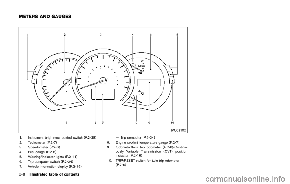
JVC0210X
1. Instrument brightness control switch (P.2-38)
2. Tachometer (P.2-7)
3. Speedometer (P.2-6)
4. Fuel gauge (P.2-8)
5. Warning/indicator lights (P.2-11)
6. Trip computer switch (P.2-24)
7. Vehicle information display (P.2-19)— Trip computer (P.2-24)
8. Engine coolant temperature gauge (P.2-7)
9. Odometer/twin trip odometer (P.2-6)/Continu- ously Variable Transmission (CVT) position
indicator (P.2-16)
10. TRIP/RESET switch for twin trip odometer (P.2-6)
METERS AND GAUGES
Page 18 of 520
SDI2715
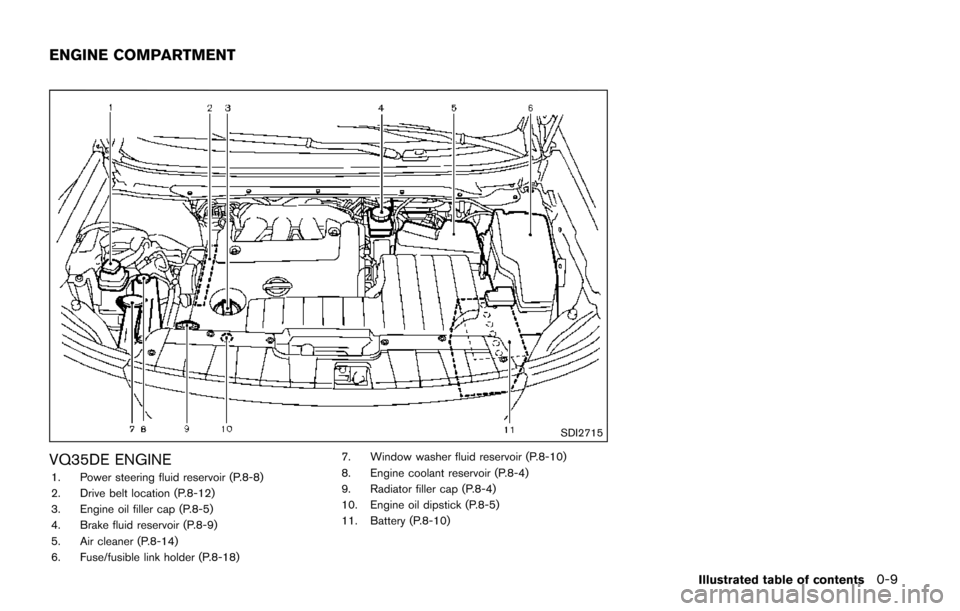
VQ35DE ENGINE
1. Power steering fluid reservoir (P.8-8)
2. Drive belt location (P.8-12)
3. Engine oil filler cap (P.8-5)
4. Brake fluid reservoir (P.8-9)
5. Air cleaner (P.8-14)
6. Fuse/fusible link holder (P.8-18)7. Window washer fluid reservoir (P.8-10)
8. Engine coolant reservoir (P.8-4)
9. Radiator filler cap (P.8-4)
10. Engine oil dipstick (P.8-5)
11. Battery (P.8-10)
Illustrated table of contents0-9
ENGINE COMPARTMENT
Page 19 of 520
0-10Illustrated table of contents
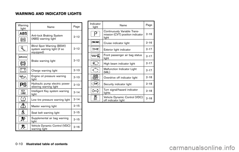
Warninglight Name
Page
Anti-lock Braking System
(ABS) warning light 2-12
Blind Spot Warning (BSW)
system warning light (if so
equipped)2-12
Brake warning light
2-12
Charge warning light2-13
Engine oil pressure warning
light2-13
Hydraulic pump electric power
steering warning light
2-13
Intelligent Key system warning
light2-14
Low tire pressure warning light
2-14
Master warning light2-15
Seat belt warning light2-15
Supplemental air bag warning
light2-15
Vehicle Dynamic Control (VDC)
warning light
2-16Indicator
light Name
Page
Continuously Variable Trans-
mission (CVT) position indicator
light 2-16
Cruise indicator light
2-16
Exterior light indicator2-17
Front passenger air bag status
light2-17
High beam indicator light
2-17
Malfunction Indicator Light
(MIL)2-17
Overdrive off indicator light
2-18
Security indicator light2-18
Turn signal/hazard indicator
lights2-18
Vehicle Dynamic Control (VDC)
off indicator light2-18
WARNING AND INDICATOR LIGHTS
Page 23 of 520
1-4Safety — Seats, seat belts and supplemental restraint system
Front power seat adjustment
Operating tips:
.The power seat motor has an auto-reset
overload protection circuit. If the motor
stops during operation, wait 30 seconds,
then reactivate the switch.
. Do not operate the power seat switch for a
long period of time when the engine is off.
This will discharge the battery.
See “Automatic drive positioner” (P.3-36) for the
seat position memory function (if so equipped) .
CAUTION
When adjusting the seat positions, be
sure not to contact any moving parts to
avoid possible injuries and/or da-
mages.
SSS1051
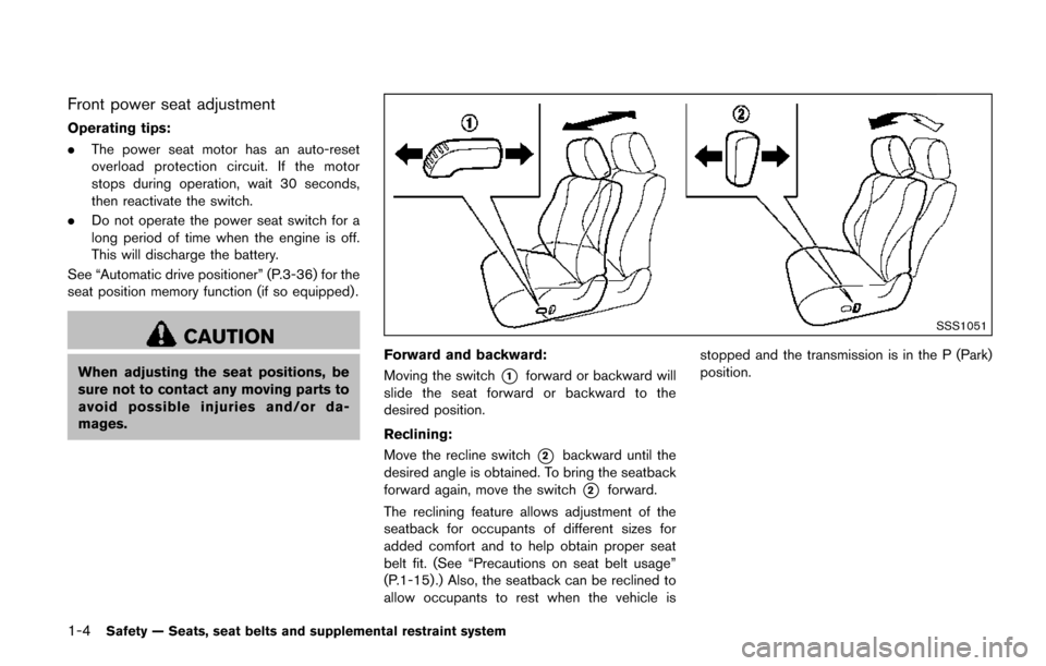
Forward and backward:
Moving the switch
*1forward or backward will
slide the seat forward or backward to the
desired position.
Reclining:
Move the recline switch
*2backward until the
desired angle is obtained. To bring the seatback
forward again, move the switch
*2forward.
The reclining feature allows adjustment of the
seatback for occupants of different sizes for
added comfort and to help obtain proper seat
belt fit. (See “Precautions on seat belt usage”
(P.1-15) .) Also, the seatback can be reclined to
allow occupants to rest when the vehicle is stopped and the transmission is in the P (Park)
position.
Page 88 of 520
2 Instruments and controls
Cockpit ........................................................................\
................ 2-3
Instrument panel ........................................................................\
2-4
Meters and gauges ................................................................... 2-5Meter/ring illumination and needle sweep .................... 2-5
Speedometer and odometer ............................................ 2-6
Tachometer ........................................................................\
... 2-7
Engine coolant temperature gauge ................................ 2-7
Fuel gauge ........................................................................\
.... 2-8
Compass (if so equipped) ...................................................... 2-8 Zone variation change procedure ................................ 2-10
Warning lights, indicator lights and
audible reminders ................................................................... 2-11 Checking lights ................................................................. 2-12
Warning lights ................................................................... 2-12
Indicator lights ................................................................... 2-16
Audible reminders ............................................................ 2-18
Vehicle information display .................................................. 2-19 Operational indicators ..................................................... 2-21
Maintenance indicators ................................................... 2-23
Trip computer .................................................................... 2-24
Security systems .................................................................... 2-28 Vehicle security system .................................................. 2-28
NISSAN vehicle immobilizer system ........................... 2-30
Wiper and washer switch .................................................... 2-31 Rear window wiper and washer switch ..................... 2-32 Rear window and outside mirror defroster switch ....... 2-33
Headlight and turn signal switch ....................................... 2-33
Xenon headlights (if so equipped) ............................ 2-33
Headlight switch ............................................................ 2-34
Turn signal switch .......................................................... 2-38
Fog light switch (if so equipped) .............................. 2-39
Horn ........................................................................\
.................. 2-39
Heated seats (if so equipped) ........................................... 2-39
Blind Spot Warning (BSW) switch (if so equipped) ..... 2-41
Vehicle Dynamic Control (VDC) OFF switch ................. 2-41
Power outlet ........................................................................\
.... 2-42
Storage ........................................................................\
............ 2-44 Cup holders ..................................................................... 2-44
Sunglasses holder ......................................................... 2-46
Glove box ........................................................................\
. 2-47
Instrument lower box (if so equipped) ..................... 2-47
Console box .................................................................... 2-47
Cargo floor box ............................................................... 2-48
Hooks ........................................................................\
........ 2-49
Roof rack (if so equipped) .......................................... 2-50
Coat hooks ...................................................................... 2-51
Sunshade (if so equipped) ................................................. 2-51
Windows ........................................................................\
......... 2-52
Power windows .............................................................. 2-52
Page 92 of 520
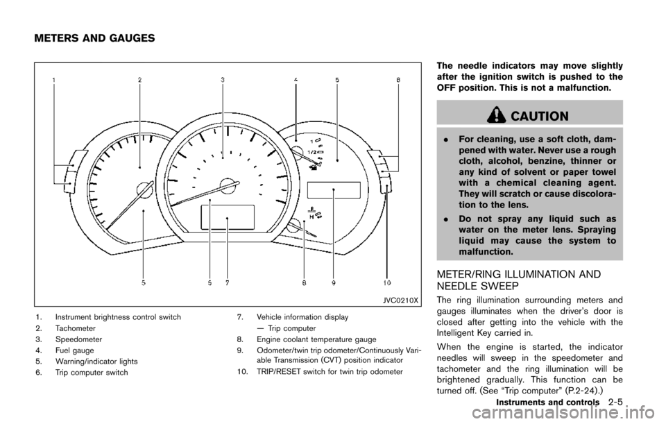
JVC0210X
1. Instrument brightness control switch
2. Tachometer
3. Speedometer
4. Fuel gauge
5. Warning/indicator lights
6. Trip computer switch7. Vehicle information display
— Trip computer
8. Engine coolant temperature gauge
9. Odometer/twin trip odometer/Continuously Vari- able Transmission (CVT) position indicator
10. TRIP/RESET switch for twin trip odometer
The needle indicators may move slightly
after the ignition switch is pushed to the
OFF position. This is not a malfunction.
CAUTION
. For cleaning, use a soft cloth, dam-
pened with water. Never use a rough
cloth, alcohol, benzine, thinner or
any kind of solvent or paper towel
with a chemical cleaning agent.
They will scratch or cause discolora-
tion to the lens.
. Do not spray any liquid such as
water on the meter lens. Spraying
liquid may cause the system to
malfunction.
METER/RING ILLUMINATION AND
NEEDLE SWEEP
The ring illumination surrounding meters and
gauges illuminates when the driver’s door is
closed after getting into the vehicle with the
Intelligent Key carried in.
When the engine is started, the indicator
needles will sweep in the speedometer and
tachometer and the ring illumination will be
brightened gradually. This function can be
turned off. (See “Trip computer” (P.2-24) .)
Instruments and controls2-5
METERS AND GAUGES
Page 94 of 520
JVI0253X
TACHOMETER
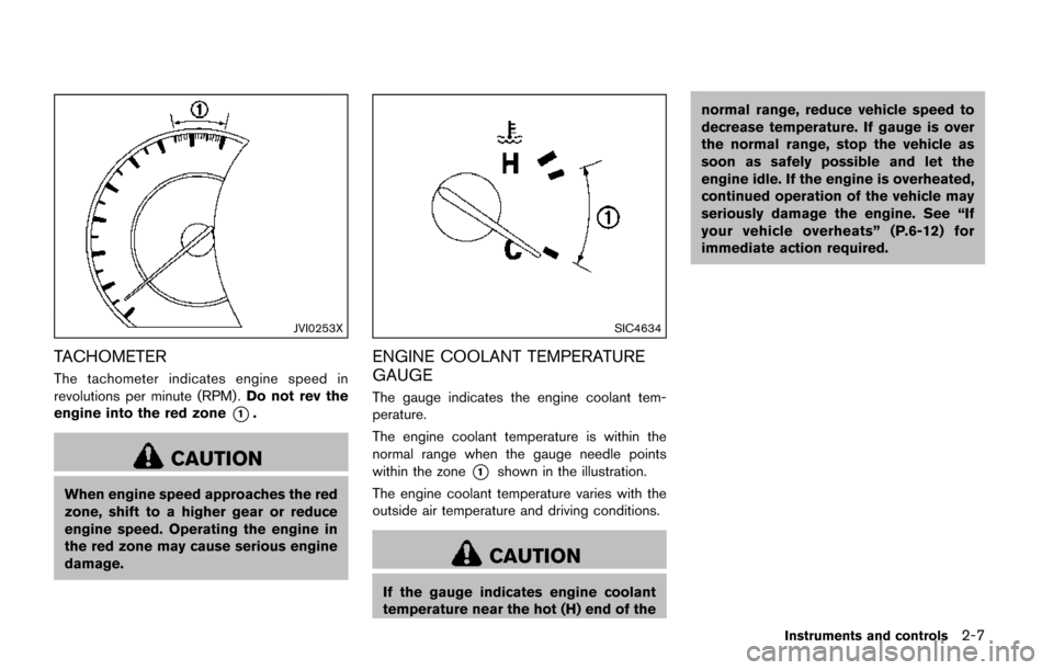
The tachometer indicates engine speed in
revolutions per minute (RPM) .Do not rev the
engine into the red zone
*1.
CAUTION
When engine speed approaches the red
zone, shift to a higher gear or reduce
engine speed. Operating the engine in
the red zone may cause serious engine
damage.
SIC4634
ENGINE COOLANT TEMPERATURE
GAUGE
The gauge indicates the engine coolant tem-
perature.
The engine coolant temperature is within the
normal range when the gauge needle points
within the zone
*1shown in the illustration.
The engine coolant temperature varies with the
outside air temperature and driving conditions.
CAUTION
If the gauge indicates engine coolant
temperature near the hot (H) end of the normal range, reduce vehicle speed to
decrease temperature. If gauge is over
the normal range, stop the vehicle as
soon as safely possible and let the
engine idle. If the engine is overheated,
continued operation of the vehicle may
seriously damage the engine. See “If
your vehicle overheats” (P.6-12) for
immediate action required.
Instruments and controls2-7