flat tire NISSAN ROGUE 2019 Owner´s Manual
[x] Cancel search | Manufacturer: NISSAN, Model Year: 2019, Model line: ROGUE, Model: NISSAN ROGUE 2019Pages: 564, PDF Size: 6.97 MB
Page 535 of 564
Steps for determining correct
load limit
1. Locate the statement “The com-bined weight of occupants and
cargo should never exceed XXX
lbs. or XXX kg” on your vehicle’s
Tire and Loading Information la-
bel.
2. Determine the combined weight of the driver and passengers
that will be riding in your vehicle.
3. Subtract the combined weight of the driver and passengers
from XXX lbs. or XXX kg.
4. The resulting figure equals the available amount of cargo and
luggage load capacity. For ex-
ample, if the XXX amount equals
1,400 lbs. and there will be five
150 lbs. passengers in your ve-
hicle, the amount of available
cargo and luggage load capac-
ity is 650 lbs. (1,400-750 (5 X 150) =
650 lbs.) or (640-340 (5 X 70) =
300 kg.) 5. Determine the combined weight
of luggage and cargo being
loaded on the vehicle. That
weight may not safely exceed
the available cargo and luggage
load capacity calculated in
step 4.
6. If your vehicle will be towing a trailer, load from your trailer will
be transferred to your vehicle.
Consult this manual to deter-
mine how this reduces the avail-
able cargo and luggage load ca-
pacity of your vehicle.
Before driving a loaded vehicle, con-
firm that you do not exceed the
Gross Vehicle Weight Rating (GVWR)
or the Gross Axle Weight Rating
(GAWR) for your vehicle. For addi-
tional information, refer to “Measure-
ment of weights” in this section.
Also check tires for proper inflation
pressures. For additional informa-
tion, refer to the “Tire and Loading
Information label” in this section.
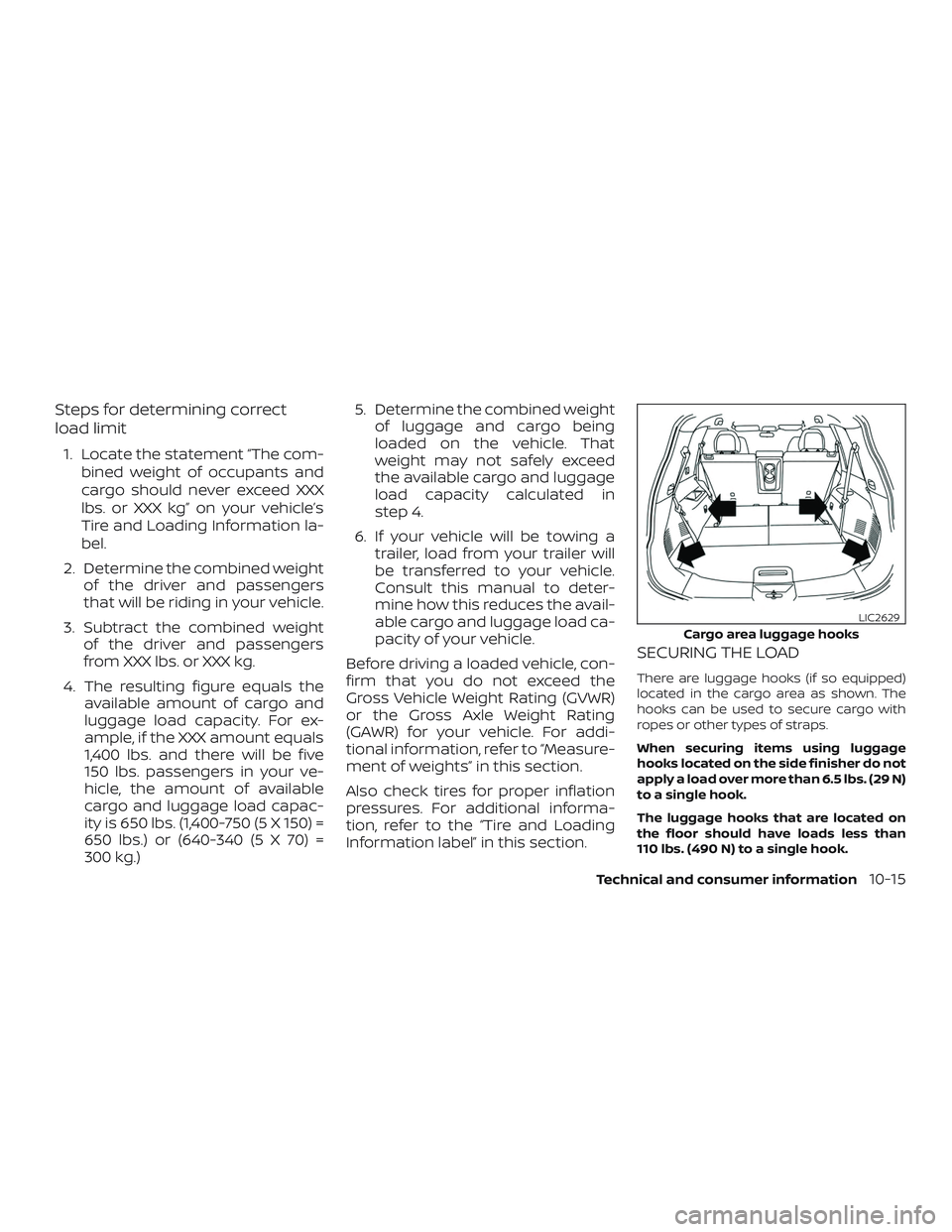
SECURING THE LOAD
There are luggage hooks (if so equipped)
located in the cargo area as shown. The
hooks can be used to secure cargo with
ropes or other types of straps.
When securing items using luggage
hooks located on the side finisher do not
apply a load over more than 6.5 lbs. (29 N)
to a single hook.
The luggage hooks that are located on
the floor should have loads less than
110 lbs. (490 N) to a single hook.
Cargo area luggage hooks
LIC2629
Technical and consumer information10-15
Page 543 of 564
2. Measure the height of a reference pointon the front and rear bumpers at the
center of the vehicle.
3. Attach the trailer to the vehicle and ad- just the hitch equalizers so that the
front bumper height is within 0 -
.5 inches (0 – 13 mm) of the reference
height measured in step 2. The rear
bumper should be no higher than the
reference height measured in step 2.
WARNING
Properly adjust the weight distributing
hitch so the rear of the bumper is no
higher than the measured reference
height when the trailer is attached. If
the rear bumper is higher than the mea-
sured reference height when loaded,
the vehicle may handle unpredictably
which could cause a loss of vehicle con-
trol and cause serious personal injury or
property damage.
Sway control device
Sudden maneuvers, wind gusts, and buf-
feting caused by other vehicles can affect
trailer handling. Sway control devices may
be used to help control these affects. If you
choose to use one, contact a reputable
trailer hitch supplier to make sure the sway control device will work with the vehicle,
hitch, trailer and the trailer’s brake system.
Follow the instructions provided by the
manufacturer for installing and using the
sway control device.
Class I hitch
Class I trailer hitch equipment (receiver, ball
mount and hitch ball) can be used to tow
trailers of a maximum weight of 2,000 lbs.
(907 kg).
Tire pressures
∙ When towing a trailer, inflate the
vehicle tires to the recom-
mended cold tire pressure indi-
cated on the Tire and Loading In-
formation label.
∙ Trailer tire condition, size, load rat- ing and proper inflation pressure
should be in accordance with the
trailer and tire manufacturer’s
specifications.
Safety chains
Always use suitable safety chains between
your vehicle and the trailer. The safety chains
should be crossed and should be attached
to the hitch, not to the vehicle bumper or
axle. The safety chains can be attached to
the bumper if the hitch ball is mounted to the
bumper. Be sure to leave enough slack in the
chains to permit turning corners.
Trailer lights
CAUTION
When splicing into the vehicle electrical
system, a commercially available power-
type module/converter must be used to
provide power for all trailer lighting. This
unit uses the vehicle battery as a direct
power source for all trailer lights while us-
ing the vehicle tail light, stop light and
turn signal circuits as a signal source. The
module/converter must draw no more
that 15 milliamps from the stop and tail
lamp circuits. Using a module/converter
that exceeds these power requirements
may damage the vehicle’s electrical sys-
tem. It is recommended that you visit a
reputable trailer retailer to obtain the
proper equipment and to have it installed.
Technical and consumer information10-23
Page 544 of 564
Trailer lights should comply with federal
and/or local regulations. For assistance in
hooking up trailer lights, contact a NISSAN
dealer or reputable trailer retailer. Vehicles
equipped with the optional trailer tow
package are equipped with a 7-pin trailer
harness connector. If your trailer is
equipped with a flat 4-pin connector, an
adapter will be needed to connect the
trailer lights to the vehicle. Adapters are
available at auto parts stores and hitch re-
tailers.
Pre-towing tips
∙ Be certain your vehicle maintains a levelposition when a loaded and/or un-
loaded trailer is hitched. Do not drive the
vehicle if it has an abnormal nose-up or
nose-down condition; check for im-
proper tongue load, overload, worn sus-
pension or other possible causes of ei-
ther condition.
∙ Always secure items in the trailer to pre- vent load shif t while driving.
∙ Keep the cargo load as low as possible in the trailer to keep the trailer center of
gravity low. ∙ Load the trailer so approximately 60%
of the trailer load is in the front half and
40% is in the back half. Also make sure
the load is balanced side to side.
∙ Check your hitch, trailer tire pressure, vehicle tire pressure, trailer light opera-
tion, and trailer wheel lug nuts every
time you attach a trailer to the vehicle.
∙ Be certain your rearview mirrors con- form to all federal, state or local regula-
tions. If not, install any mirrors required
for towing before driving the vehicle.
∙ Determine the overall height of the ve- hicle and trailer so the required clear-
ance is known.
Trailer towing tips
In order to gain skill and an understanding
of the vehicle’s behavior, you should prac-
tice turning, stopping and backing up in an
area which is free from traffic. Steering sta-
bility and braking performance will be
somewhat different than under normal
driving conditions.
∙ Always secure items in the trailer to pre- vent load shif t while driving. ∙ Lock the trailer hitch coupler with a pin
or lock to prevent the coupler from in-
advertently becoming unlatched.
∙ Avoid abrupt starts, acceleration or stops.
∙ Avoid sharp turns or lane changes.
∙ Always drive your vehicle at a moderate speed.
∙ When backing up, hold the bottom of the steering wheel with one hand. Move
your hand in the direction in which you
want the trailer to go. Make small cor-
rections and back up slowly. If possible,
have someone guide you when you are
backing up.
Always block the wheels on both vehicle
and trailer when parking. Parking on a
slope is not recommended; however, if you
must do so:
CAUTION
If you move the shif t lever to the P (Park)
position before blocking the wheels
and applying the parking brake, trans-
mission damage could occur.
10-24Technical and consumer information
Page 547 of 564
∙ Never tow your front wheel drive ve-hicle with the front tires on the
ground. Doing so may cause serious
and expensive damage to the
powertrain.
∙ DO NOT tow your front wheel drive continuously variable transmission
vehicle with all four wheels on the
ground (flat towing). Doing so WILL
DAMAGE internal transmission parts
due to lack of transmission
lubrication.
∙ For emergency towing procedures re- fer to “Towing recommended by
NISSAN” in the “In case of emergency ”
section of this manual.
Continuously Variable
Transmission
To tow a vehicle equipped with a continu-
ously variable transmission, an appropriate
vehicle dolly MUSTbe placed under the
towed vehicle’s drive wheels. Alwaysfollow
the dolly manufacturer’s recommenda-
tions when using their product. DOT (Department of Transportation) Qual-
ity Grades: All passenger car tires must
conform to federal safety requirements in
addition to these grades.
Quality grades can be found where appli-
cable on the tire sidewall between tread
shoulder and maximum section width. For
example:
Treadwear 200 Traction AA Temperature A
Treadwear
The treadwear grade is a comparative rat-
ing based on the wear rate of the tire when
tested under controlled conditions on a
specified government test course. For ex-
ample, a tire graded 150 would wear one
and one-half (1 1/2) times as well on the
government course as a tire graded 100.
The relative performance of tires depends
upon the actual conditions of their use,
however, and may depart significantly from
the norm due to variations in driving habits,
service practices and differences in road
characteristics and climate.
Traction AA, A, B and C
The traction grades, from highest to low-
est, are AA, A, B, and C. Those grades repre-
sent the tire’s ability to stop on wet pave-
ment as measured under controlledconditions on specified government test
surfaces of asphalt and concrete. A tire
marked C may have poor traction perfor-
mance.
WARNING
The traction grade assigned to this tire
is based on straight-ahead braking
traction tests, and does not include ac-
celeration, cornering, hydroplaning, or
peak traction characteristics.
Temperature A, B and C
The temperature grades are A (the high-
est), B, and C, representing the tire’s resis-
tance to the generation of heat, and its
ability to dissipate heat when tested under
controlled conditions on a specified indoor
laboratory test wheel. Sustained high tem-
perature can cause the material of the tire
to degenerate and reduce tire life, and ex-
cessive temperature can lead to sudden
tire failure. The grade C corresponds to a
level of performance which all passenger
car tires must meet under the Federal Mo-
tor Vehicle Safety Standard No. 109. Grades
B and A represent higher levels of perfor-
mance on the laboratory test wheel than
the minimum required by law.
UNIFORM TIRE QUALITY GRADING
Technical and consumer information10-27
Page 548 of 564
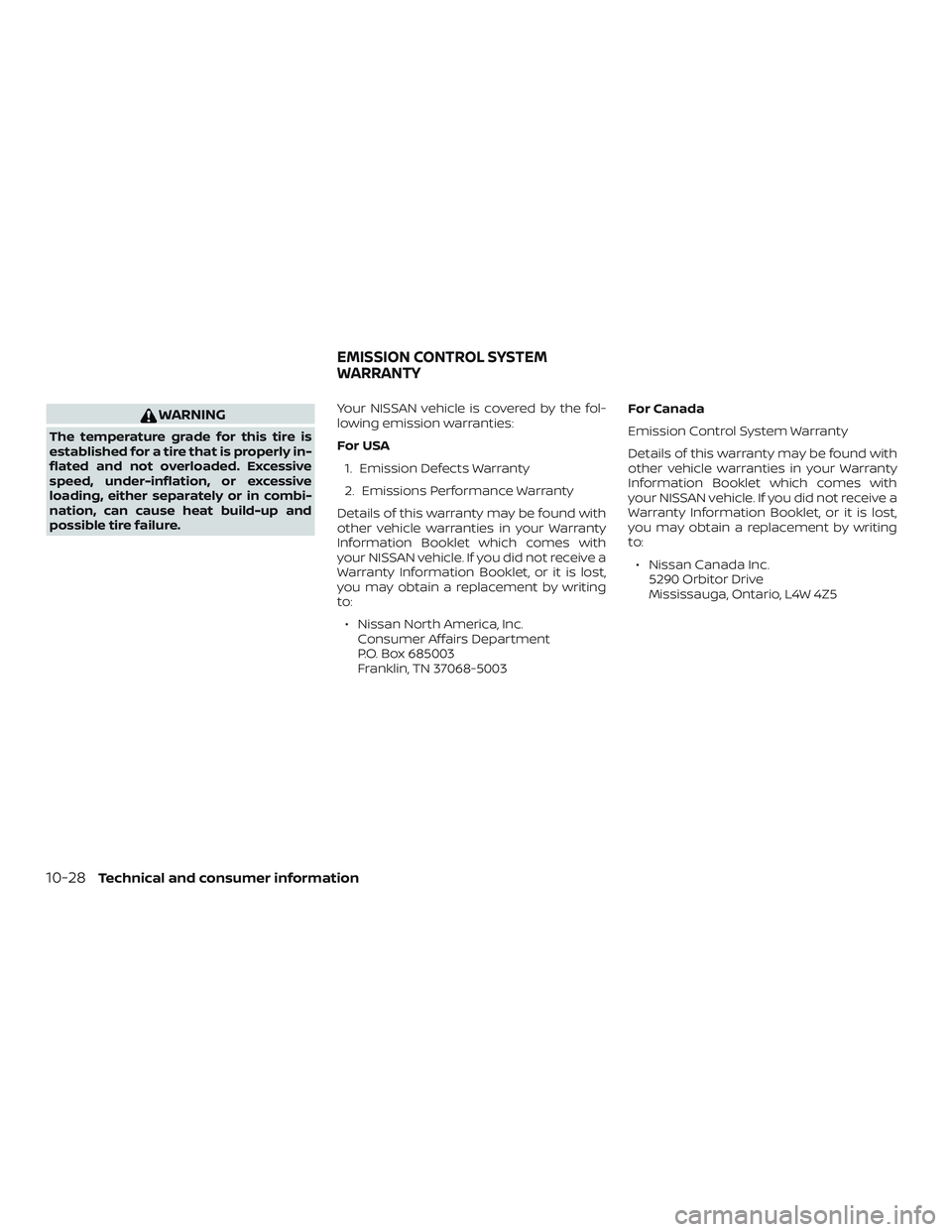
WARNING
The temperature grade for this tire is
established for a tire that is properly in-
flated and not overloaded. Excessive
speed, under-inflation, or excessive
loading, either separately or in combi-
nation, can cause heat build-up and
possible tire failure.Your NISSAN vehicle is covered by the fol-
lowing emission warranties:
For USA
1. Emission Defects Warranty
2. Emissions Performance Warranty
Details of this warranty may be found with
other vehicle warranties in your Warranty
Information Booklet which comes with
your NISSAN vehicle. If you did not receive a
Warranty Information Booklet, or it is lost,
you may obtain a replacement by writing
to: ∙ Nissan North America, Inc. Consumer Affairs Department
P.O. Box 685003
Franklin, TN 37068-5003 For Canada
Emission Control System Warranty
Details of this warranty may be found with
other vehicle warranties in your Warranty
Information Booklet which comes with
your NISSAN vehicle. If you did not receive a
Warranty Information Booklet, or it is lost,
you may obtain a replacement by writing
to:
∙ Nissan Canada Inc. 5290 Orbitor Drive
Mississauga, Ontario, L4W 4Z5
EMISSION CONTROL SYSTEM
WARRANTY
10-28Technical and consumer information
Page 554 of 564
Childrestraints........1-21, 1-22, 1-24, 1-26LATCH (Lower Anchors and Tethers for
CHildren)System..............1-26
Precautions on child
restraints..........1-24, 1-31, 1-37, 1-42
Top tether strap anchor point
locations...................1-29
Child restraint with top tether strap . . . .1-28
Child safety rear door lock ..........3-7
Chimes, audible reminders .........2-21
Cleaningexteriorandinterior......7-2,7-4
C.M.V.S.S. certification label .........10-11
Coldweatherdriving ............5-168
Console box ..................2-64
Console light ..................2-76
Continuously Variable Transmission
(CVT) ....................5-14,5-21
Continuously Variable Transmission (CVT)
fluid......................8-10
Driving with Continuously Variable
Transmission (CVT) .........5-14,5-21
Controls Heater and air conditioner
controls................4-29,4-38
Coolant Capacities and recommended
fuel/lubricants...............10-2
Changing engine coolant .........8-5
Checking engine coolant level ......8-5
Engine coolant temperature gauge . .2-6
Corrosionprotection..............7-7
Cruisecontrol.................5-65
Cupholders ..................2-65 D
Defroster switch Rear window and outside mirror
defrosterswitch..............2-47
Dimensions and weights ...........10-9
Dimmer switch for instrument panel . . .2-53
Display......................2-22
Door locks ..................3-5,3-6
Drivebelt.....................8-17
Drive positioner, Automatic ......3-44,3-45
Driving Cold weather driving ..........5-168
Driving with Continuously Variable
Transmission (CVT) .........5-14,5-21
Precautions when starting and
driving..................5-4,5-11
Drivingthevehicle...............5-21
Dynamic driver assistance switch
(for vehicles without ProPILOT Assist) . . .2-57
E
E-call (SOS) Button ..............2-60
ECO mode switch ...............5-34
Economy - fuel ................5-148
Emergency engine shutoff ..........5-17
Emission control information label . . . .10-11
Emission control system warranty . . . .10-28
Engine Before starting the engine ........5-19
Capacities and recommended
fuel/lubricants...............10-2
Changing engine coolant .........8-5
Changing engine oil ............8-7 Changing engine oil filter
.........8-7
Checking engine coolant level ......8-5
Checking engine oil level .........8-6
Engine compartment check
locations...................8-3
Engine coolant temperature gauge . .2-6
Engine cooling system ..........8-4
Engine oil ...................8-6
Engine oil and oil filter
recommendation .............10-6
Engine oil viscosity .............10-6
Engine serial number ...........10-11
Engine specifications ...........10-8
Starting the engine ............5-19
Engine coolant temperature gauge ....2-6
EventDatarecorders.........10-30,10-31
Exhaust gas (Carbon monoxide) .......5-4
Explanation of maintenance items .....9-3
Explanation of scheduled maintenance
items .......................9-6
Extended storage switch ..........2-62
Eyeglasscase.................2-65
F
Flashers
(Seehazardwarningflasherswitch)....6-2
Flattire......................6-3
Floormatpositioningaid...........7-6
Fluid Brakefluid..................8-11
Capacities and recommended
fuel/lubricants...............10-2
Continuously Variable Transmission (CVT)
f
luid......................8-10
11-2
Page 559 of 564
TireFlattire....................6-3
Spare tire ................6-5,8-43
Tire and Loading Information label . .10-12
Tire chains .................8-39
Tire pressure ................8-32
Tirerotation ................8-40
Types of tires ................8-38
Uniform tire quality grading ......10-27
Wheels and tires ..............8-32
Wheel/tire size ...............10-9
Tire pressure Low tire pressure warning light .....2-14
Tire Pressure Monitoring System (TPMS) . .5-5
Toptetherstrapchildrestraint.......1-28
Towing 4-wheel drive models ...........6-16
Flattowing.................10-26
Towing load/specification .......10-20
Towtrucktowing .............6-14
Trailertowing ...............10-17
Towingatrailer................10-17
Transceiver HomeLink® Universal
Transceiver .......2-78,2-79,2-81,2-82
Transmission Continuously Variable Transmission
(CVT) fluid ..................8-10
Driving with Continuously Variable
Transmission (CVT) .........5-14,5-21
Travel (See registering a vehicle in another
country) .....................10-10
Trip odometer ..................2-5
Turn signal switch ...............2-53 U
Uniform tire quality grading ........10-27
USB/iPod® Charging Ports .........4-42
V
Vanitymirror..................3-40
Variable voltage control system ......8-17
Vehicle dimensions and weights ......10-9
Vehicle Dynamic Control (VDC) OFF
switch......................2-58
Vehicle Dynamic Control (VDC)
system .....................5-156
Vehicle identification .............10-10
Vehicle identification number (VIN) . . . .10-10
Vehicle identification number (VIN)
(Chassis number) ...............10-10
Vehicle identification number (VIN)
plate.......................10-10
Vehicle immobilizer system . .2-44, 5-14, 5-18
VehicleInformationDisplay.........2-22
Vehicle loading information ........10-13
Vehiclerecovery.............6-16,6-17
Vehicle security system ...........2-42
Vehicle security system (NISSAN Vehicle
Immobilizer System), engine
start.................2-44,5-14,5-18
Ventilators ...................4-28
Visors ......................3-39 W
Warning Airbagwarninglight........1-65, 2-17
Anti-lock brake warning light ......2-12
Battery charge warning light ......2-13
Brakewarninglight............2-13
Hazard warning flasher switch ......6-2
Loose fuel cap warning ......2-36,3-38
Lowfuelwarninglight.......2-16,2-36
Lowtirepressurewarninglight.....2-14
Low windshield-washer fluid warning
light......................2-36
Passenger air bag and status light. . .1-56
Seatbeltwarninglight .......1-15, 2-17
Supplemental air bag warning
light...................1-65, 2-17
TPMS......................2-4
Vehicle security system .........2-42
Warning/indicator lights and audible
reminders ...............2-12,2-18
Warning labels (for SRS) .........1-64
Warning/indicator lights and audible
reminders .................2-12,2-18
Audible reminders ..........2-12,2-18
Checking bulbs ...............2-12
Indicatorlights............2-12,2-18
Warninglights............2-12,2-18
Warninglights..............2-12,2-18
Warning lights, indicator lights and audible
reminders ....................2-11
11-7