instrument panel NISSAN ROGUE 2023 Owner's Manual
[x] Cancel search | Manufacturer: NISSAN, Model Year: 2023, Model line: ROGUE, Model: NISSAN ROGUE 2023Pages: 508, PDF Size: 2.44 MB
Page 239 of 508

OPERATING TIPS (for automatic air
conditioner)
When the engine coolant temperature
and outside air temperature are low, the
air flow from the foot outlets may not
operate for a maximum of 150 seconds.
However, this is not a malfunction. After
the coolant temperature warms up, air
flow from the foot outlets will operate
normally.
The sensors
and, located on the
instrument panel, help maintain a con-
stant temperature. Do not put anything
on or around the sensors.
SERVICING AIR CONDITIONER
WARNING
The air conditioner system contains
refrigerant under high pressure. To
avoid personal injury, any air condi-
tioner service should be done only by
an experienced technician with the
proper equipment.
The air conditioner system in your vehicle
is charged with a refrigerant designed
with the environment in mind.
This refrigerant will not harm the
earth’s ozone layer. However, it maycontribute in a small part to global
warming.
Special charging equipment and lubricant
are required when servicing your vehicle’s
air conditioner. Using improper refriger-
ants or lubricants will cause severe da-
mage to the air conditioner system. (See
“Air conditioning system refrigerant and
oil recommendations” (P.10-6).)
A NISSAN dealer will be able to service
your environmentally friendly air condi-
tioner system.
In-cabin microfilter
The air conditioner system is equipped
with an in-cabin microfilter. To make sure
the air conditioner heats, defogs, and
ventilates efficiently, replace the filter
according to the specified maintenance
intervals listed in the "9. Maintenance and
schedules" section. It is recommended to
visit a NISSAN dealer to replace the filter.
The filter should be replaced if the air flow
decreases significantly or if windows fog
up easily when operating the heater or air
conditioner.SAA2374
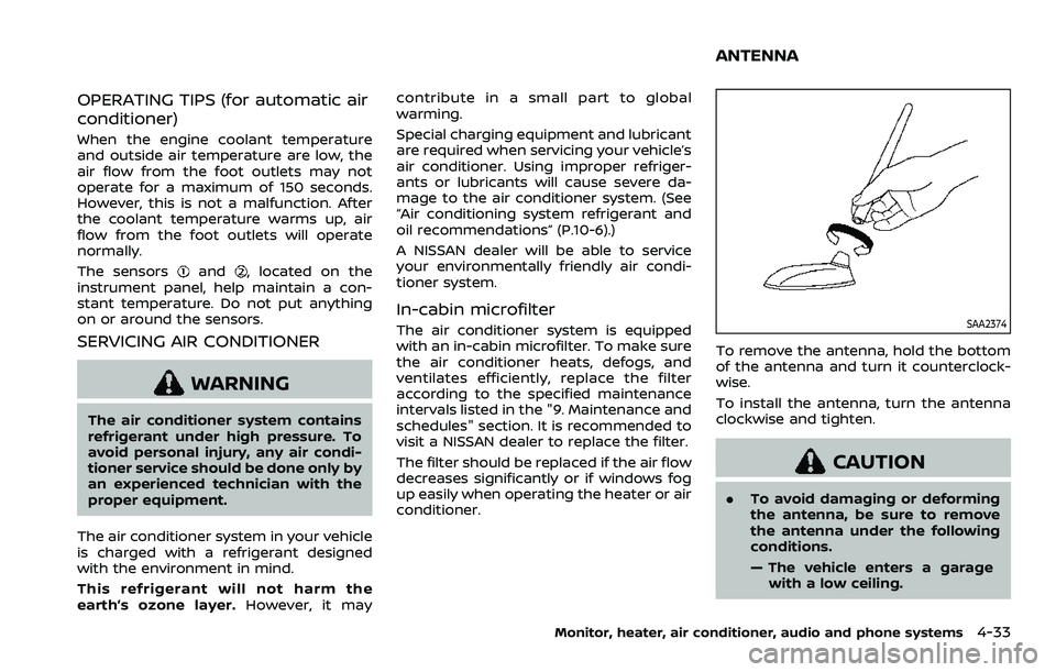
To remove the antenna, hold the bottom
of the antenna and turn it counterclock-
wise.
To install the antenna, turn the antenna
clockwise and tighten.
CAUTION
.
To avoid damaging or deforming
the antenna, be sure to remove
the antenna under the following
conditions.
— The vehicle enters a garage
with a low ceiling.
Monitor, heater, air conditioner, audio and phone systems4-33
ANTENNA
Page 255 of 508

start the engine.
.The cargo room area is not included in
the operating range but the Intelligent
Key may function.
. If the Intelligent Key is placed on the
instrument panel, inside the glove box
or door pocket, the Intelligent Key may
not function.
. If the Intelligent Key is placed near the
door or window outside the vehicle,
the Intelligent Key may function.
PUSH-BUTTON IGNITION SWITCH
OPERATION
CAUTION
.Do not leave the vehicle for ex-
tended periods of time when the
ignition switch is in the ON posi-
tion and the engine is not run-
ning. This can discharge the
battery.
. Use electrical accessories with
the engine running to avoid dis-
charging the vehicle battery. If
you must use accessories while
the engine is not running, do not
use them for extended periods of
time and do not use multiple
electrical accessories at the same time.
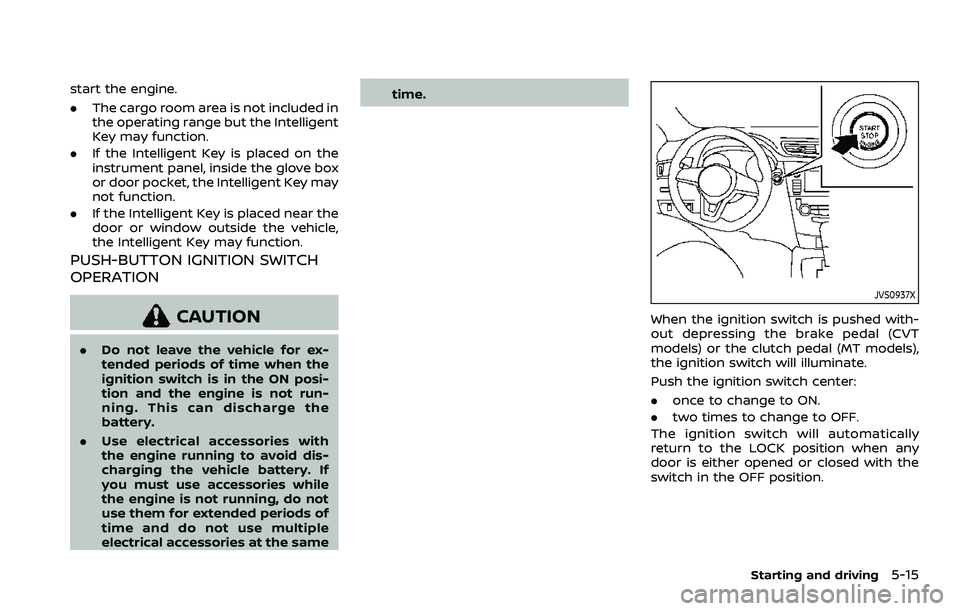
JVS0937X
When the ignition switch is pushed with-
out depressing the brake pedal (CVT
models) or the clutch pedal (MT models),
the ignition switch will illuminate.
Push the ignition switch center:
.
once to change to ON.
. two times to change to OFF.
The ignition switch will automatically
return to the LOCK position when any
door is either opened or closed with the
switch in the OFF position.
Starting and driving5-15
Page 272 of 508

5-32Starting and driving
applied and the brake force of the
automatic brake hold will be re-
leased:
—The braking force is applied by
the automatic brake hold function
for 3 minutes or longer.
— The driver’s seat belt is unfas-
tened.
— The ignition switch is placed in
the OFF position.
— If a malfunction occurs in the
automatic brake hold function.
. When the vehicle stops, but the
brake force is not automatically
applied, depress the brake pedal
firmly until the automatic brake hold
indicator light (green) illuminates.
Automatic brake hold function dis-
play
The automatic brake hold function status
can be checked in the “Chassis Control”
mode in the vehicle information display.
For additional information, see “Trip com-
puter” (P.2-40).
WAF0037X
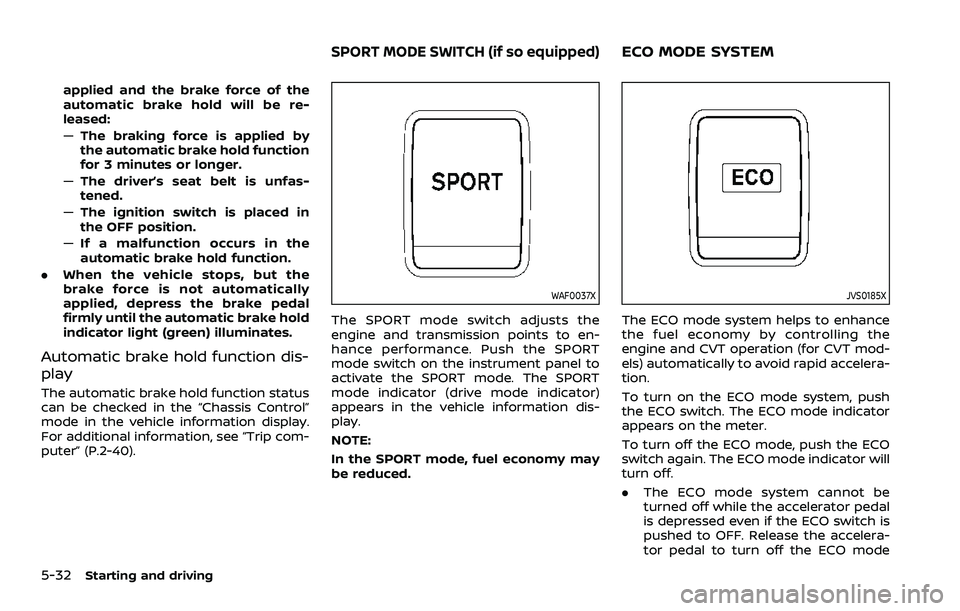
The SPORT mode switch adjusts the
engine and transmission points to en-
hance performance. Push the SPORT
mode switch on the instrument panel to
activate the SPORT mode. The SPORT
mode indicator (drive mode indicator)
appears in the vehicle information dis-
play.
NOTE:
In the SPORT mode, fuel economy may
be reduced.
JVS0185X
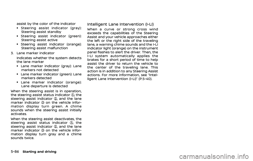
The ECO mode system helps to enhance
the fuel economy by controlling the
engine and CVT operation (for CVT mod-
els) automatically to avoid rapid accelera-
tion.
To turn on the ECO mode system, push
the ECO switch. The ECO mode indicator
appears on the meter.
To turn off the ECO mode, push the ECO
switch again. The ECO mode indicator will
turn off.
.The ECO mode system cannot be
turned off while the accelerator pedal
is depressed even if the ECO switch is
pushed to OFF. Release the accelera-
tor pedal to turn off the ECO mode
SPORT MODE SWITCH (if so equipped)ECO MODE SYSTEM
Page 279 of 508

the LDW system will resume operating
automatically and the LDW indicator will
stop flashing.
Condition B:
The warning function of the LDW system
is not designed to work under the follow-
ing conditions:
.When you operate the lane change
signal and change traveling lanes in
the direction of the signal. (The LDW
system will become operable again
approximately 2 seconds after the
lane change signal is turned off.)
. When the vehicle speed lowers to less
than approximately 37 MPH (60 km/h).
Action to take:
After the above conditions have finished
and the necessary operating conditions
are satisfied, the LDW system will resume.SYSTEM MALFUNCTION
If the LDW system malfunctions, it will
cancel automatically and “Malfunction”
will appear in the vehicle information
display. If the warning message appears
in the vehicle information display, pull off
the road to a safe location and stop the
vehicle. Place the ignition switch in the
OFF position and restart the engine. If the
warning message continues to appear in
the vehicle information display, have the
system checked. It is recommended that
you visit a NISSAN dealer for this service.
WAC0198X
SYSTEM MAINTENANCE
The camera unitfor the LDW system is
located above the inside mirror.
To keep the proper operation of the LDW
system and prevent a system malfunc-
tion, be sure to observe the following:
. Always keep the windshield clean.
. Do not attach a sticker (including
transparent material) or install an
accessory near the camera unit.
. Do not place reflective materials, such
as white paper or a mirror, on the
instrument panel. The reflection of
sunlight may adversely affect the
camera unit’s capability of detecting
the lane markers.
Starting and driving5-39
Page 283 of 508

For models without ProPILOT assist
1. To turn on the I-LI system, push thedynamic driver assistance switch on
the instrument panel after starting
the engine.
2. The I-LI ON indicator on the Vehicle Information Display will appear.
3. Push the dynamic driver assistance switch again to turn off the I-LI
system. The I-LI ON indicator on the
vehicle information display will turn
off. The I-LI system will be automati-
cally turned off when the engine off.
I-LI SYSTEM LIMITATIONS
WARNING
Listed below are the system limita-
tions for the I-LI system. Failure to
follow the warnings and instructions
for proper use of the I-LI system
could result in serious injury or
death.
.The I-LI system may activate if
you change lanes without first
activating your turn signal or, for
example, if a construction zone
directs traffic to cross an existing
lane marker. If this occurs you
may need to apply corrective steering to complete your lane
change.
. Because the I-LI may not activate
under the road, weather, and lane
marker conditions described in
this section, it may not activate
every time your vehicle begins to
leave its lane and you will need to
apply corrective steering.
. The I-LI system will not operate at
speeds below approximately 37
MPH (60 km/h) or if it cannot
detect lane markers.
. Do not use the I-LI system under
the following conditions as it may
not function properly:
— During bad weather (rain, fog,
snow, etc.).
— When driving on slippery roads, such as on ice or snow.
— When driving on winding or uneven roads.
— When there is a lane closure due to road repairs.
— When driving in a makeshift or temporary lane.
— When driving on roads where the lane width is too narrow. — When driving without normal
tire conditions (for example,
tire wear, low tire pressure,
installation of spare tire (if so
equipped), tire chains, non-
standard wheels).
— When the vehicle is equipped with non-original brake parts
or suspension parts.
. The system may not function
properly under the following con-
ditions:
— On roads where there are
multiple parallel lane markers;
lane markers that are faded or
not painted clearly; yellow
painted lane markers; non-
standard lane markers; or
lane markers covered with
water, dirt, snow, etc.
— On roads where discontinued lane markers are still detect-
able.
— On roads where there are sharp curves.
— On roads where there are sharply contrasting objects,
such as shadows, snow,
water, wheel ruts, seams or
lines remaining after road re-
Starting and driving5-43
Page 285 of 508

exist, turn off the I-LI system. Push the
dynamic driver assistance switch (models
without ProPILOT assist) or the ProPILOT
assist switch (models with ProPILOT as-
sist) again to turn the I-LI system back on.
Temporary disabled status at high tem-
perature:
If the vehicle is parked in direct sunlight
under high temperature conditions (over
approximately 104°F (40°C)) and then the
I-LI system is turned on, the I-LI system
may be deactivated automatically and
the following message will appear on
the vehicle information display: “Unavail-
able: High Cabin Temperature.” When the
interior temperature is reduced, the sys-
tem will resume operating automatically.
SYSTEM MALFUNCTION
If the I-LI system malfunctions, it will
cancel automatically. The I-LI indicator
(orange) will illuminate and the “Malfunc-
tion” warning message will appear in the
display.
If the I-LI indicator (orange) illuminates in
the display, pull off the road to a safe
location. Turn the engine off and restart
the engine. If the I-LI indicator (orange)
continues to illuminate, have the I-LI
system checked. It is recommended that
you visit a NISSAN dealer for this service.
WAC0198X
SYSTEM MAINTENANCE
The camera unitfor the I-LI system is
located above the inside mirror. To keep
the proper operation of the I-LI system
and prevent a system malfunction, be
sure to observe the following:
. Always keep the windshield clean.
. Do not attach a sticker (including
transparent material) or install an
accessory near the camera unit.
. Do not place reflective materials, such
as white paper or a mirror, on the
instrument panel. The reflection of
sunlight may adversely affect the
camera unit’s capability of detecting
the lane markers. .
Do not strike or damage the areas
around the camera unit. Do not touch
the camera lens or remove the screw
located on the camera unit. If the
camera unit is damaged due to an
accident, it is recommended that you
visit a NISSAN dealer.
Starting and driving5-45
Page 314 of 508

5-74Starting and driving
WAF0055X
1. Steering-wheel-mounted control (left)
2. Vehicle information display
3. Steering assist switch
NOTE:
.When the steering assist switch is
used to turn the system on or off,
the system remembers the setting even if the ignition switch is cycled.
The switch must be pushed again to
change the setting to on or off.
. The steering assist switch changes
the status of the “Steering Assist”
selection made in the “Settings”
screen in the vehicle information
display. Steering assist switch:
To turn the steering assist on or off, push
the steering assist switch
on the
instrument panel.
Setting in the vehicle information dis-
play:
1. Press the
button on the
steering wheeluntil “Settings” ap-
pears in the vehicle information dis-
play
and then press “OK” button.
2. Use the
buttonto select “Driver
Assistance.” Then press the “OK” but-
ton
.
3. Use the
buttonto select “Driving
Aids.” Then press the “OK” button.
4. Select “Steering Assist” and press the “OK” button
.
NOTE:
. When the Cruise screen is displayed
on the vehicle information display,
press the “OK” button on the steer-
ing wheel to call up the “Driving Aids”
setting display.
. When enabling/disabling the system
through the vehicle information dis-
play, the system retains the current
settings even if the engine is re-
started.
Page 324 of 508

5-84Starting and driving
ICC system malfunction
If the ICC system malfunctions, it will be
turned off automatically, a chime will
sound, and the speed control status
warning (orange) will illuminate.
Action to take:
If the warning illuminates, stop the vehicle
in a safe place. Turn the engine off, restart
the engine and set the ICC system again.
If it is not possible to set the ICC system or
the warning stays on, it may be a
malfunction. Although the normal driving
can be continued, the ICC system should
be inspected. It is recommended that you
visit a NISSAN dealer for this service.
ICC sensor maintenance
The radar sensor is located on the front of
the vehicle.
To keep the ICC system operating prop-
erly, be sure to observe the following:
.Always keep the sensor area clean.
. Do not strike or damage the areas
around the sensor.
. Do not attach a sticker (including
transparent material) or install an
accessory near the sensor. This could
cause failure or malfunction.
. Do not attach metallic objects near
the sensor area (brush guard, etc.).
This could cause failure or malfunc- tion.
. Do not alter, remove, or paint the front
bumper.
Before customizing or restoring the front
bumper, it is recommended that you visit
a NISSAN dealer.
The camera sensor is located above the
inside mirror.
To keep the proper operation of the
systems and prevent a system malfunc-
tion, be sure to observe the following:
. Always keep the windshield clean.
. Do not attach a sticker (including
transparent material) or install an
accessory near the camera unit.
. Do not place reflective materials, such
as white paper or a mirror, on the
instrument panel. The reflection of
sunlight may adversely affect the
camera unit’s capability of detecting
the lane markers.
. Do not strike or damage the areas
around the camera unit. Do not touch
the camera lens or remove the screw
located on the camera unit.
If the camera unit is damaged due to an
accident, it is recommended that you visit
a NISSAN dealer.
STEERING ASSIST
WARNING
Failure to follow the warnings and
instructions for proper use of the
steering assist could result in serious
injury or death.
. The steering assist is not a repla-
cement for proper driving proce-
dures and is not designed to
correct careless, inattentive or
absent-minded driving. The
steering assist will not always
steer the vehicle to keep it in the
lane. It is not designed to prevent
loss of control. It is the driver’s
responsibility to stay alert, drive
safely, keep the vehicle in the
traveling lane, and be in control
of the vehicle at all times.
. As there is a performance limit to
the steering assist’s capability,
never rely solely on the system.
The steering assist does not func-
tion in all driving, traffic, weather,
and road conditions. Always drive
safely, pay attention to the op-
eration of the vehicle, and manu-
ally control your vehicle
appropriately.
Page 326 of 508

5-86Starting and driving
assist by the color of the indicator.Steering assist indicator (gray):Steering assist standby
.Steering assist indicator (green):
Steering assist active
.Steering assist indicator (orange): Steering assist malfunction
3. Lane marker indicator
Indicates whether the system detects
the lane marker
.Lane marker indicator (gray): Lanemarkers not detected
.Lane marker indicator (green): Lanemarkers detected
.Lane marker indicator (orange):Lane departure is detected
When the steering assist is in operation,
the steering assist status indicator
, the
steering assist indicator, and the lane
marker indicatoron the vehicle infor-
mation display turn green. A chime
sounds when the steering assist initially
activates.
When the steering assist deactivates, the
steering assist status indicator
, the
steering assist indicator, and the lane
marker indicatoron the vehicle infor-
mation display turn gray and a chime
sounds twice.
Intelligent Lane Intervention (I-LI)
When a curve or strong cross wind
exceeds the capabilities of the Steering
Assist and your vehicle approaches either
the left or the right side of the traveling
lane, a warning chime sounds and the I-LI
indicator light (orange) on the instrument
panel flashes to alert the driver. Then, the
I-LI system automatically applies the
brakes for a short period of time to help
assist the driver to return the vehicle to
the center of the traveling lane. This
action is in addition to any Steering Assist
actions. For more information, see “Intel-
ligent Lane Intervention (I-LI)” (P.5-40).
Page 330 of 508

5-90Starting and driving
Action to take:
Stop the vehicle in a safe location, place
the shift lever in the P (Park) position, turn
the engine off, restart the engine, resume
driving, and set the ICC system again. If
the warning (orange) continues to illumi-
nate, the steering assist is malfunctioning.
Although the vehicle is still drivable under
normal conditions, have the system
checked. It is recommended that you visit
a NISSAN dealer for this service.
Steering assist maintenance
The camera is located above the inside
mirror.
To keep the proper operation of the
system and prevent a system malfunc-
tion, be sure to observe the following:
.Always keep the windshield clean.
. Do not attach a sticker (including
transparent material) or install an
accessory near the camera unit.
. Do not place reflective materials, such
as white paper or a mirror, on the
instrument panel. The reflection of
sunlight may adversely affect the
camera unit’s capability of detecting
the lane markers.
. Do not strike or damage the areas
around the camera unit. Do not touch
the camera lens or remove the screw
located on the camera unit. If the camera unit is damaged due to an
accident, it is recommendedthat you visit
a NISSAN dealer.
Radio frequency statement:
For USA
FCC ID OAYARS4B
This device complies with Part 15 of the
FCC Rules. Operation is subject to the
following two conditions:
1. This device may not cause harmful
interference, and
2. This device must accept any interfer- ence received, including interference
that may cause undesired operation.
FCC Warning
Changes or modifications not expressly
approved by the party responsible for
compliance could void the user’s author-
ity to operate the equipment.
For Canada
Model: ARS4–B
IC: 4135A-ARS4B
FCC ID: OAYARS4B
This device complies with Part 15 of the
FCC Rules and with Industry Canada
licence-exempt RSS standard(s). Opera-
tion is subject to the following two con-
ditions: 1. This device may not cause harmful
interference, and
2. This device must accept any interfer- ence received, including interference
that may cause undesired operation.
Le present appareil est conforme aux CNR
d’Industrie Canada applicables aux appa-
reils radio exempts de licence. L’exploita-
tion est autorisee aux deux conditions
suivantes:
1. L’appareil ne doit pas produire de brouillage, et
2. L’utilisateur de l’appareil doit accepter tout brouillage radioelectrique subi,
meme si le brouillage est susceptible
d’en compromettre le fonctionne-
ment.
Radio Frequency Radiation Exposure In-
formation:
This equipment complies with FCC radia-
tion exposure limits set forth for an
uncontrolled environment.
This equipment should be installed and
operated with minimum distance of 30
cm between the radiator and your body.
The transmitter must not be co-located
or operating in conjunction with any
other antenna or transmitter.
Cet equipement est conforme aux limites
d’exposition aux rayonnements IC eta-