key NISSAN ROGUE 2023 Service Manual
[x] Cancel search | Manufacturer: NISSAN, Model Year: 2023, Model line: ROGUE, Model: NISSAN ROGUE 2023Pages: 508, PDF Size: 2.44 MB
Page 205 of 508
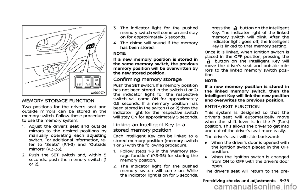
WAD0097X
MEMORY STORAGE FUNCTION
Two positions for the driver’s seat and
outside mirrors can be stored in the
memory switch. Follow these procedures
to use the memory system.
1. Adjust the driver’s seat and outsidemirrors to the desired positions by
manually operating each adjusting
switch. For additional information, re-
fer to “Seats” (P.1-3) and “Outside
mirrors” (P.3-33).
2. Push the SET switch and, within 5 seconds, push the memory switch (1
or 2). 3. The indicator light for the pushed
memory switch will come on and stay
on for approximately 5 seconds.
4. The chime will sound if the memory has been stored.
NOTE:
If a new memory position is stored in
the same memory switch, the previous
memory position will be overwritten by
the new stored position.
Confirming memory storage
Push the SET switch. If a memory position
has not been stored in the switch (1 or 2)
the indicator light for the respective
switch will come ON for approximately
0.5 seconds. If a memory position has
been stored in the switch (1 or 2) then the
indicator light for the respective switch
will stay ON for approximately 5 seconds.
Linking an Intelligent Key to a
stored memory position
Each Intelligent Key can be linked to a
stored memory position (memory switch
1 or 2) with the following procedure.
1. Follow steps 1-3 in the “Memory sto- rage function” (P.3-35) for storing the
memory position.
2. The indicator light for the pushed memory switch will come on. While
the indicator light is on for 5 seconds, press the
button on the Intelligent
Key. The indicator light of the linked
memory switch will blink. After the
indicator light goes off, the Intelligent
Key is linked to that memory setting.
Once it is linked, when ignition switch is
placed in the OFF position, pressing the
button on the Intelligent Key will
move the driver’s seat and outside mir-
rors to the linked memory switch posi-
tion.
NOTE:
If a new memory position is stored in
the linked memory switch, then the
Intelligent Key will link the new position
and overwrites the previous position.
ENTRY/EXIT FUNCTION
This system is designed so that the
driver’s seat will automatically move
when the shift lever is in the P (Park)
position. This allows the driver to get into
and out of the driver’s seat more easily.
The driver’s seat will slide backward:
. When the driver’s door is opened with
the ignition switch placed in the OFF
position.
. When the ignition switch is changed
from ON to OFF with the driver’s door
open.
The driver’s seat will return to the pre-
Pre-driving checks and adjustments3-35
Page 214 of 508
4-8Monitor, heater, air conditioner, audio and phone systems
WAE0058X
ADJUSTING THE SCREEN
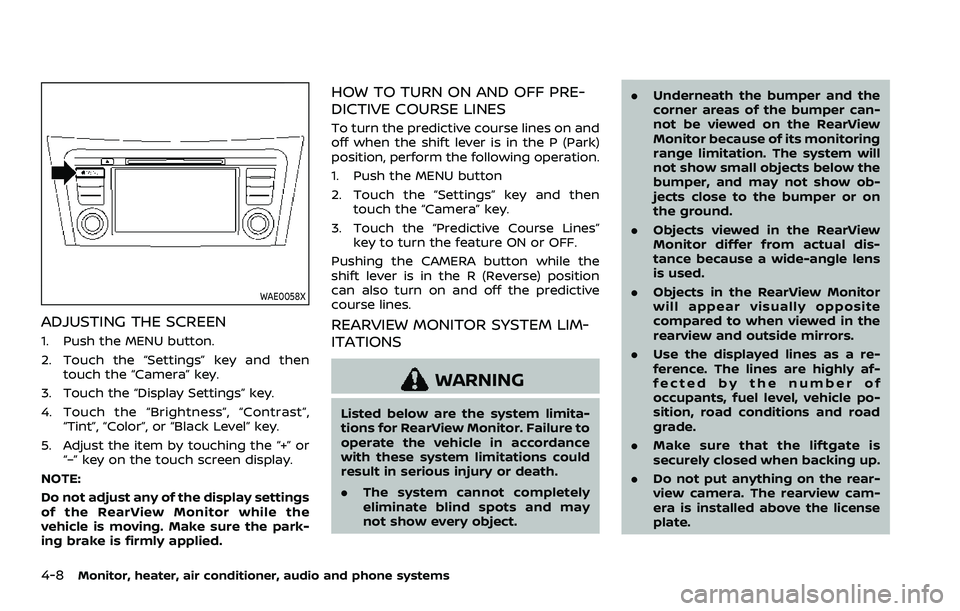
1. Push the MENU button.
2. Touch the “Settings” key and thentouch the “Camera” key.
3. Touch the “Display Settings” key.
4. Touch the “Brightness”, “Contrast”, “Tint”, “Color”, or “Black Level” key.
5. Adjust the item by touching the “+” or “–” key on the touch screen display.
NOTE:
Do not adjust any of the display settings
of the RearView Monitor while the
vehicle is moving. Make sure the park-
ing brake is firmly applied.
HOW TO TURN ON AND OFF PRE-
DICTIVE COURSE LINES
To turn the predictive course lines on and
off when the shift lever is in the P (Park)
position, perform the following operation.
1. Push the MENU button
2. Touch the “Settings” key and then touch the “Camera” key.
3. Touch the “Predictive Course Lines” key to turn the feature ON or OFF.
Pushing the CAMERA button while the
shift lever is in the R (Reverse) position
can also turn on and off the predictive
course lines.
REARVIEW MONITOR SYSTEM LIM-
ITATIONS
WARNING
Listed below are the system limita-
tions for RearView Monitor. Failure to
operate the vehicle in accordance
with these system limitations could
result in serious injury or death.
. The system cannot completely
eliminate blind spots and may
not show every object. .
Underneath the bumper and the
corner areas of the bumper can-
not be viewed on the RearView
Monitor because of its monitoring
range limitation. The system will
not show small objects below the
bumper, and may not show ob-
jects close to the bumper or on
the ground.
. Objects viewed in the RearView
Monitor differ from actual dis-
tance because a wide-angle lens
is used.
. Objects in the RearView Monitor
will appear visually opposite
compared to when viewed in the
rearview and outside mirrors.
. Use the displayed lines as a re-
ference. The lines are highly af-
fected by the number of
occupants, fuel level, vehicle po-
sition, road conditions and road
grade.
. Make sure that the liftgate is
securely closed when backing up.
. Do not put anything on the rear-
view camera. The rearview cam-
era is installed above the license
plate.
Page 224 of 508
4-18Monitor, heater, air conditioner, audio and phone systems
.A different screen is selected.
WAE0058X
ADJUSTING THE SCREEN
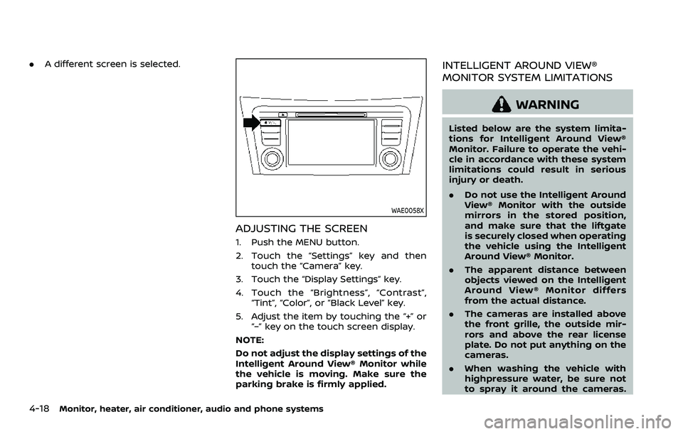
1. Push the MENU button.
2. Touch the “Settings” key and then
touch the “Camera” key.
3. Touch the “Display Settings” key.
4. Touch the “Brightness”, “Contrast”, “Tint”, “Color”, or “Black Level” key.
5. Adjust the item by touching the “+” or “–” key on the touch screen display.
NOTE:
Do not adjust the display settings of the
Intelligent Around View® Monitor while
the vehicle is moving. Make sure the
parking brake is firmly applied.
INTELLIGENT AROUND VIEW®
MONITOR SYSTEM LIMITATIONS
WARNING
Listed below are the system limita-
tions for Intelligent Around View®
Monitor. Failure to operate the vehi-
cle in accordance with these system
limitations could result in serious
injury or death.
. Do not use the Intelligent Around
View® Monitor with the outside
mirrors in the stored position,
and make sure that the liftgate
is securely closed when operating
the vehicle using the Intelligent
Around View® Monitor.
. The apparent distance between
objects viewed on the Intelligent
Around View® Monitor differs
from the actual distance.
. The cameras are installed above
the front grille, the outside mir-
rors and above the rear license
plate. Do not put anything on the
cameras.
. When washing the vehicle with
highpressure water, be sure not
to spray it around the cameras.
Page 241 of 508
5 Starting and driving
Precautions when starting and driving ...................... 5-4Exhaust gas (carbon monoxide) ................................ 5-4
Three-way catalyst ............................................................... 5-4
Tire Pressure Monitoring System (TPMS) ........... 5-5
Avoiding collision and rollover .................................... 5-8
On-pavement and off-road
driving precautions .............................................................. 5-9
Off-road recovery .................................................................. 5-9
Rapid air pressure loss ...................................................... 5-9
Drinking alcohol/drugs and driving ..................... 5-10
Driving safety precautions .......................................... 5-10
Ignition switch (models without Intelligent
Key system) ........................................................................\
............ 5-12
Continuously Variable
Transmission (CVT) ............................................................ 5-13
Manual Transmission (MT) ........................................... 5-13
Key positions ........................................................................\
.. 5-14
Push-button ignition switch (model with
Intelligent Key system) .......................................................... 5-14 Operating range for engine start function ...... 5-14
Push-button ignition switch operation ............. 5-15
Push-button ignition switch positions .............. 5-16
Emergency engine shut off ........................................ 5-16
Intelligent Key battery discharge ........................... 5-17
Before starting the engine ................................................. 5-17 Starting the engine (model without Intelligent
Key system) ........................................................................\
........... 5-18
Starting the engine (model with Intelligent
Key system) ........................................................................\
........... 5-19
Remote engine start (if so equipped) .............. 5-20
Driving the vehicle ................................................................... 5-20
Continuously Variable
Transmission (CVT) ......................................................... 5-20
Manual Transmission (MT) ........................................ 5-25
Parking brake ........................................................................\
....... 5-27
Pedal type ........................................................................\
....... 5-27
Switch type (models with electronic
parking brake system) ................................................. 5-27
Automatic brake hold (if so equipped) .................... 5-29 How to activate/deactivate the automatic
brake hold function ........................................................ 5-30
How to use the automatic brake
hold function ........................................................................\
5-31
SPORT mode switch (if so equipped) ....................... 5-32
ECO mode system ................................................................... 5-32
ECO Pedal Guide function ......................................... 5-33
Ambient ECO ........................................................................\
5-34
ECO Drive Report .............................................................. 5-34
Lane Departure Warning (LDW) ..................................... 5-35 LDW system operation ................................................. 5-36
How to enable/disable the LDW system ....... 5-37
Page 252 of 508
5-12Starting and driving
similar equipment even if the
other two wheels are raised off
the ground. Make sure you inform
test facility personnel that your
vehicle is equipped with AWD
before it is placed on a dynam-
ometer. Using the wrong test
equipment may result in drive-
train damage or unexpected ve-
hicle movement which could
result in serious vehicle damage
or personal injury.
. When a wheel is off the ground
due to an unlevel surface, do not
spin the wheel excessively (AWD
model).
. Accelerating quickly, sharp steer-
ing maneuvers or sudden braking
may cause loss of control.
. If at all possible, avoid sharp
turning maneuvers, particularly
at high speeds. Your vehicle has
a higher center of gravity than a
conventional passenger car. The
vehicle is not designed for cor-
nering at the same speeds as
conventional passenger cars.
Failure to operate this vehicle
correctly could result in loss of
control and/or a rollover acci-
dent. .
Always use tires of the same type,
size, brand, construction (bias,
bias-belted or radial), and tread
pattern on all four wheels. Install
traction devices on the front
wheels when driving on slippery
roads and drive carefully.
. Be sure to check the brakes im-
mediately after driving in mud or
water. See “Brake system” (P.5-
129) for wet brakes.
. Avoid parking your vehicle on
steep hills. If you get out of the
vehicle and it rolls forward, back-
ward or sideways, you could be
injured.
. Whenever you drive off-road
through sand, mud or water as
deep as the wheel hub, more
frequent maintenance may be
required. See the maintenance
schedule shown in the “9. Main-
tenance and schedules” section.
. Spinning the front wheels on
slippery surfaces may cause the
AWD warning message to display
and the AWD system to automa-
tically switch from the AWD mode
to the 2WD mode. This could
reduce traction. (AWD models)WARNING
Never remove the key or place the
ignition switch in the LOCK position
while driving. The steering wheel will
lock and could cause the driver to
lose control of the vehicle. This could
result in serious vehicle damage or
personal injury.
IGNITION SWITCH (models without
Intelligent Key system)
Page 253 of 508
JVS1067X
CONTINUOUSLY VARIABLE TRANS-
MISSION (CVT)
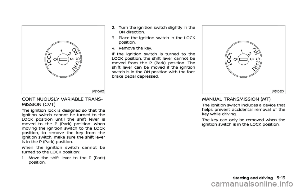
The ignition lock is designed so that the
ignition switch cannot be turned to the
LOCK position until the shift lever is
moved to the P (Park) position. When
moving the ignition switch to the LOCK
position, to remove the key from the
ignition switch, make sure the shift lever
is in the P (Park) position.
When the ignition switch cannot be
turned to the LOCK position:
1. Move the shift lever to the P (Park)position. 2. Turn the ignition switch slightly in the
ON direction.
3. Place the ignition switch in the LOCK position.
4. Remove the key.
If the ignition switch is turned to the
LOCK position, the shift lever cannot be
moved from the P (Park) position. The
shift lever can be moved if the ignition
switch is in the ON position with the foot
brake pedal depressed.
JVS1067X
MANUAL TRANSMISSION (MT)
The ignition switch includes a device that
helps prevent accidental removal of the
key while driving.
The key can only be removed when the
ignition switch is in the LOCK position.
Starting and driving5-13
Page 254 of 508
5-14Starting and driving
KEY POSITIONS
LOCK: Normal parking position (0)
OFF: (Not used) (1)
This position activates electrical acces-
sories such as the radio when the engine
is not running.
ON: Normal operating position (2)
This position turns on the ignition system
and the electrical accessories.
START: (3)
This position starts the engine. As soon as
the engine has started, release the key. It
automatically returns to the ON position.
WARNING
Do not operate the push-button
ignition switch while driving the ve-
hicle except in an emergency. (The
engine will stop when the ignition
switch is pushed 3 consecutive times
or the ignition switch is pushed and
held for more than 2 seconds.) If the
engine stops while the vehicle is
being driven, this could lead to a
crash and serious injury.
Before operating the push-button igni-
tion switch, be sure to move the shift
lever to the P (Park) position (for Con-
tinuously Variable Transmission (CVT)
models) or the shift lever to the N
(Neutral) position (for Manual Transmis-
sion (MT) models).
SSD0436
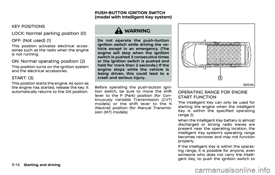
OPERATING RANGE FOR ENGINE
START FUNCTION
The Intelligent Key can only be used for
starting the engine when the Intelligent
Key is within the specified operating
range
.
When the Intelligent Key battery is almost
discharged or strong radio waves are
present near the operating location, the
Intelligent Key system’s operating range
becomes narrower and may not function
properly.
If the Intelligent Key is within the operat-
ing range, it is possible for anyone, even
someone who does not carry the Intelli-
gent Key, to push the ignition switch to
PUSH-BUTTON IGNITION SWITCH
(model with Intelligent Key system)
Page 255 of 508
start the engine.
.The cargo room area is not included in
the operating range but the Intelligent
Key may function.
. If the Intelligent Key is placed on the
instrument panel, inside the glove box
or door pocket, the Intelligent Key may
not function.
. If the Intelligent Key is placed near the
door or window outside the vehicle,
the Intelligent Key may function.
PUSH-BUTTON IGNITION SWITCH
OPERATION
CAUTION
.Do not leave the vehicle for ex-
tended periods of time when the
ignition switch is in the ON posi-
tion and the engine is not run-
ning. This can discharge the
battery.
. Use electrical accessories with
the engine running to avoid dis-
charging the vehicle battery. If
you must use accessories while
the engine is not running, do not
use them for extended periods of
time and do not use multiple
electrical accessories at the same time.
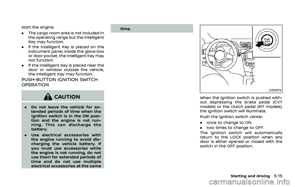
JVS0937X
When the ignition switch is pushed with-
out depressing the brake pedal (CVT
models) or the clutch pedal (MT models),
the ignition switch will illuminate.
Push the ignition switch center:
.
once to change to ON.
. two times to change to OFF.
The ignition switch will automatically
return to the LOCK position when any
door is either opened or closed with the
switch in the OFF position.
Starting and driving5-15
Page 256 of 508
5-16Starting and driving
Continuously Variable Transmis-
sion (CVT) models
The ignition lock is designed so that the
ignition switch position cannot be
switched to OFF until the shift lever is
moved to the P (Park) position.
When the ignition switch cannot be
pushed toward the OFF position, proceed
as follows:
1. Move the shift lever into the P (Park)position.
2. Push the ignition switch. The ignition switch position will change to the ON
position.
3. Push the ignition switch again to the OFF position.
The shift lever can be moved from the P
(Park) position if the ignition switch is in
the ON position and the brake pedal is
depressed.
PUSH-BUTTON IGNITION SWITCH
POSITIONS
LOCK (Normal parking position)
The ignition switch can only be locked at
this position.
The ignition switch will lock when any
door is opened or closed with the ignition
switched off.
ON (Normal operating position)
The ignition system and the electrical
accessory power activate at this position
without the engine turned on.
The ON position has a battery saver
feature that will place the ignition switch
in the OFF position, if the vehicle is not
running, after some time under the fol-
lowing conditions:
. all doors are closed.
. shift lever is in P (Park) position (CVT
model) or N (Neutral) position (MT
model).
The battery saver feature will be can-
celled if any of the following occur:
. any door is opened.
. shift lever is moved out of the P (Park)
position (CVT model). .
ignition switch changes position.
OFF position
The engine is turned off in this position.
Auto ACC position
With the vehicle in the P (Park) position
(CVT models) or the N (Neutral) position
(MT models), the Intelligent Key with you
and the ignition placed from ON to OFF,
the radio can still be used for a period of
time, or until the driver’s door is opened.
After a period of time, functions such as
radio, navigation (if so equipped), and
Bluetooth® Hands-Free Phone System
may be restarted by turning on the audio
system (see the separate NissanConnect®
Owner’s Manual), or by pushing the UN-
LOCK button on the Intelligent Key for up
to a total of 30 minutes.
EMERGENCY ENGINE SHUT OFF
To shut off the engine in an emergency
situation while driving, perform the fol-
lowing procedure:
.Rapidly push the push-button ignition
switch 3 consecutive times in less
than 1.5 seconds, or
. Push and hold the push-button igni-
tion switch for more than 2 seconds.
Page 257 of 508
JVS0404X
INTELLIGENT KEY BATTERY DIS-
CHARGE
If the battery of the Intelligent Key is
discharged, or environmental conditions
interfere with the Intelligent Key opera-
tion, start the engine according to the
following procedure:
1. Move the shift lever to the P (Park)position (for CVT models) or the shift
lever to the N (Neutral) position (for MT
models).
2. Firmly apply the foot brake.
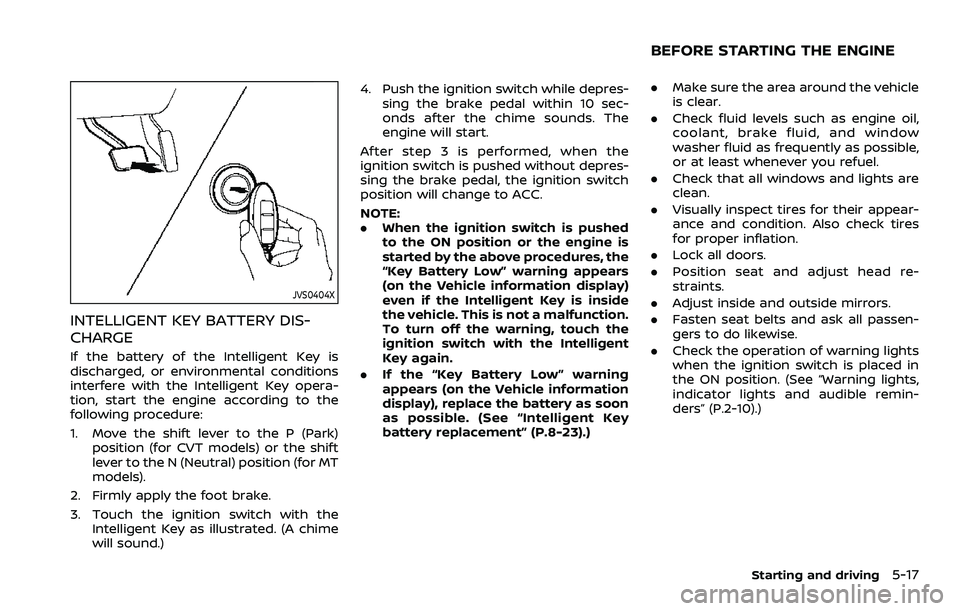
3. Touch the ignition switch with the Intelligent Key as illustrated. (A chime
will sound.) 4. Push the ignition switch while depres-
sing the brake pedal within 10 sec-
onds after the chime sounds. The
engine will start.
After step 3 is performed, when the
ignition switch is pushed without depres-
sing the brake pedal, the ignition switch
position will change to ACC.
NOTE:
. When the ignition switch is pushed
to the ON position or the engine is
started by the above procedures, the
“Key Battery Low” warning appears
(on the Vehicle information display)
even if the Intelligent Key is inside
the vehicle. This is not a malfunction.
To turn off the warning, touch the
ignition switch with the Intelligent
Key again.
. If the “Key Battery Low” warning
appears (on the Vehicle information
display), replace the battery as soon
as possible. (See “Intelligent Key
battery replacement” (P.8-23).)
.Make sure the area around the vehicle
is clear.
. Check fluid levels such as engine oil,
coolant, brake fluid, and window
washer fluid as frequently as possible,
or at least whenever you refuel.
. Check that all windows and lights are
clean.
. Visually inspect tires for their appear-
ance and condition. Also check tires
for proper inflation.
. Lock all doors.
. Position seat and adjust head re-
straints.
. Adjust inside and outside mirrors.
. Fasten seat belts and ask all passen-
gers to do likewise.
. Check the operation of warning lights
when the ignition switch is placed in
the ON position. (See “Warning lights,
indicator lights and audible remin-
ders” (P.2-10).)
Starting and driving5-17
BEFORE STARTING THE ENGINE