tow NISSAN ROGUE SPORT 2018 Owners Manual
[x] Cancel search | Manufacturer: NISSAN, Model Year: 2018, Model line: ROGUE SPORT, Model: NISSAN ROGUE SPORT 2018Pages: 512, PDF Size: 3.33 MB
Page 33 of 512
1-14Safety — Seats, seat belts and supplemental restraint system
Fastening the seat belts
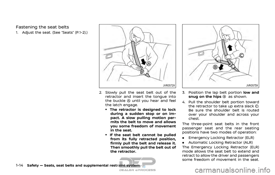
1. Adjust the seat. (See “Seats” (P.1-2).)
JVR0572X
2. Slowly pull the seat belt out of theretractor and insert the tongue into
the buckle
until you hear and feel
the latch engage.
.The retractor is designed to lock
during a sudden stop or on im-
pact. A slow pulling motion per-
mits the belt to move and allows
you some freedom of movement
in the seat.
.If the seat belt cannot be pulledfrom its fully retracted position,
firmly pull the belt and release it.
Then smoothly pull the belt out of
the retractor.
JVR0573X
3. Position the lap belt portion low and
snug on the hipsas shown.
4. Pull the shoulder belt portion toward the retractor to take up extra slack
.
Be sure the shoulder belt is routed
over your shoulder and across your
chest.
The three-point seat belts in the front
passenger seat and the rear seating
positions have two modes of operation:
. Emergency Locking Retractor (ELR)
. Automatic Locking Retractor (ALR)
The Emergency Locking Retractor (ELR)
mode allows the seat belt to extend and
retract to allow the driver and passengers
some freedom of movement in the seat.
Page 58 of 512

LRS0454
Front passenger position
3. The booster seat should be positionedon the vehicle seat so that it is stable.
If necessary, adjust or remove the
head restraint to obtain the correct
booster seat fit. If the head restraint is
removed, store it in a secure place. Be
sure to reinstall the head restraint
when the booster seat is removed.
See “Head restraints/headrests” (P.1-6)
for head restraint adjustment, re-
moval and installation information.
If the seating position does not have a
head restraint and it is interfering with
the proper booster seat fit, try another
seating position or a different booster
seat. 4. Position the lap portion of the seat
belt low and snug on the child’s hips.
Be sure to follow the booster seat
manufacturer’s instructions for ad-
justing the seat belt routing.
5. Pull the shoulder belt portion of the seat belt toward the retractor to take
up extra slack. Be sure the shoulder
belt is positioned across the top,
middle portion of the child’s shoulder.
Be sure to follow the booster seat
manufacturer’s instructions for ad-
justing the seat belt routing.
6. Follow the warnings, cautions and instructions for properly fastening a
seat belt shown in “Seat belts” (P.1-10).
SSS0676
7. If the booster seat is installed in thefront passenger seat, place the igni-
tion switch in the ON position. The
front passenger air bag status light
may or may not illuminate de-
pending on the size of the child and
the type of booster seat used. See
“Front passenger air bag and status
light” (P.1-48).
Safety — Seats, seat belts and supplemental restraint system1-39
Page 72 of 512
eration of the air bag system and
result in serious personal injury.
. Do not use water or acidic clea-
ners (hot steam cleaners) on the
seat. This can damage the seat or
occupant classification sensors.
This can also affect the operation
of the air bag system and result in
serious personal injury.
. Immediately after inflation, sev-
eral front air bag system compo-
nents will be hot. Do not touch
them; you may severely burn
yourself.
. No unauthorized changes should
be made to any components or
wiring of the supplemental air
bag system. This is to prevent
accidental inflation of the supple-
mental air bag or damage to the
supplemental air bag system.
. Do not make unauthorized
changes to your vehicle’s electri-
cal system, suspension system or
front end structure. This could
affect proper operation of the
front air bag system.
. Tampering with the front air bag
system may result in serious per-
sonal injury. Tampering includes
changes to the steering wheel and the instrument panel assem-
bly by placing material over the
steering wheel pad and above the
instrument panel or by installing
additional trim material around
the air bag system.
. Removing or modifying the front
passenger seat may affect the
function of the air bag system
and result in serious personal
injury.
. Modifying or tampering with the
front passenger seat may result
in serious personal injury. For
example, do not change the front
seats by placing material on the
seat cushion or by installing ad-
ditional trim material, such as
seat covers, on the seat that is
not specifically designed to as-
sure proper air bag operation.
Additionally, do not stow any
objects under the front passen-
ger seat or the seat cushion and
seatback. Such objects may inter-
fere with the proper operation of
the occupant classification sen-
sors.
. No unauthorized changes should
be made to any components or
wiring of the seat belt system.
This may affect the front air bag system. Tampering with the seat
belt system may result in serious
personal injury.
. It is recommended you visit a
NISSAN dealer for work on and
around the front air bag. It is also
recommended you visit a NISSAN
dealer for installation of electrical
equipment. The Supplemental
Restraint System (SRS) wiring
harnesses* should not be modi-
fied or disconnected. Unauthor-
ized electrical test equipment
and probing devices should not
be used on the air bag system.
. A cracked windshield should be
replaced immediately by a quali-
fied repair facility. A cracked
windshield could affect the func-
tion of the supplemental air bag
system.
*The SRS wiring harness connectors are
yellow and orange for easy identifica-
tion.
When selling your vehicle, we request that
you inform the buyer about the front air
bag system and guide the buyer to the
appropriate sections in this Owner’s Man-
ual.
Safety — Seats, seat belts and supplemental restraint system1-53
Page 82 of 512
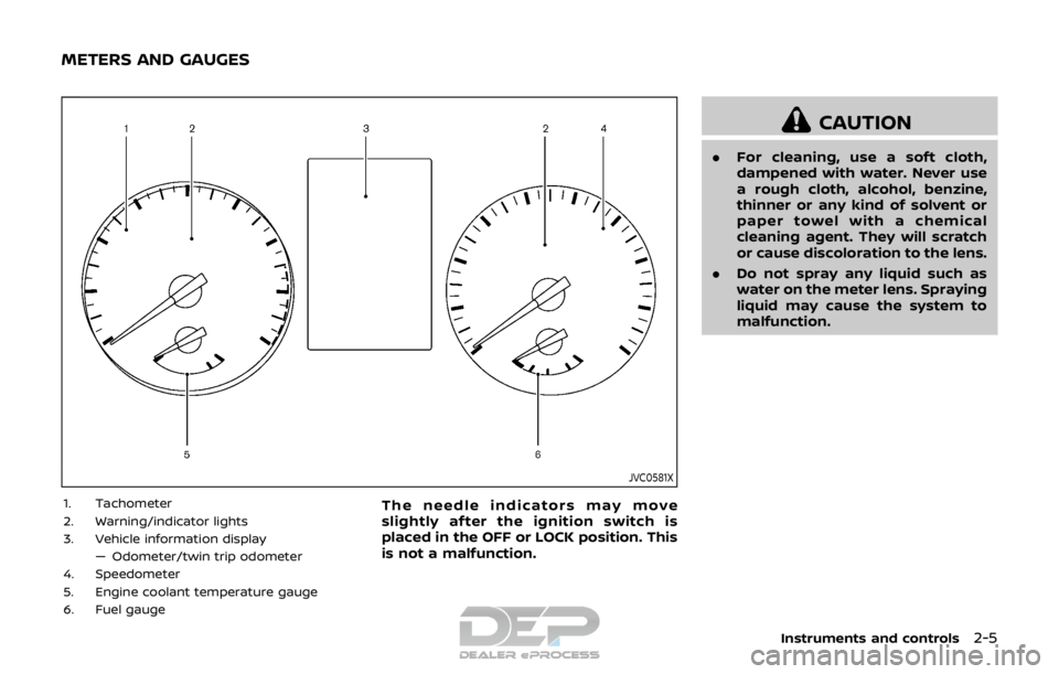
JVC0581X
1. Tachometer
2. Warning/indicator lights
3. Vehicle information display— Odometer/twin trip odometer
4. Speedometer
5. Engine coolant temperature gauge
6. Fuel gaugeThe needle indicators may move
slightly after the ignition switch is
placed in the OFF or LOCK position. This
is not a malfunction.
CAUTION
. For cleaning, use a soft cloth,
dampened with water. Never use
a rough cloth, alcohol, benzine,
thinner or any kind of solvent or
paper towel with a chemical
cleaning agent. They will scratch
or cause discoloration to the lens.
. Do not spray any liquid such as
water on the meter lens. Spraying
liquid may cause the system to
malfunction.
Instruments and controls2-5
METERS AND GAUGES
Page 88 of 512
recommended you visit a NISSAN dealer
for this service.
If an ABS malfunction occurs, the anti-
lock function is turned off. The brake
system then operates normally, but with-
out anti-lock assistance. (See “Brake sys-
tem” (P.5-106).)
orBrake warning light
(red)
This light functions for both the parking
brake and the foot brake systems.
Parking brake indicator (models not
equipped with electronic parking brake
system):
When the ignition switch is in the ON
position, the light illuminates when the
parking brake is applied.
Low brake fluid warning light:
When the ignition switch is placed in the
ON position, the brake warning light
illuminates, and then turns off (models
equipped with electronic parking brake
system). If the light illuminates while the
engine is running with the parking brake
not applied, stop the vehicle and perform
the following:
1. Check the brake fluid level. If brake fluid is necessary, add fluid and have
the system checked. It is recom- mended you have this service per-
formed by a NISSAN dealer. (See
“Brake and clutch fluid” (P.8-9).)
2. If the brake fluid level is correct, have the warning system checked. It is
recommended you have this service
performed by a NISSAN dealer.
Anti-lock Braking System (ABS) warning
indicator:
When the parking brake is released and
the brake fluid level is sufficient, if both
the brake warning light and the Anti-lock
Braking System (ABS) warning light illu-
minate, it may indicate the ABS is not
functioning properly. Have the brake
system checked, and if necessary re-
paired. It is recommended you visit a
NISSAN dealer for this service. (See “Anti-
lock Braking System (ABS) warning light”
(P.2-10).)
WARNING
. Your brake system may not be
working properly if the warning
light is on. Driving could be dan-
gerous. If you judge it to be safe,
drive carefully to the nearest
service station for repairs. Other-
wise, have your vehicle towed
because driving it could be dan- gerous.
. Pressing the brake pedal with the
engine stopped and/or low brake
fluid level may increase your
stopping distance and braking
will require greater pedal effort
as well as pedal travel.
. If the brake fluid level is below the
minimum or MIN mark on the
brake fluid reservoir, do not drive
until the brake system has been
checked. It is recommended you
visit a NISSAN dealer for this
service.
Charge warning light
If the light illuminates while the engine is
running, it may indicate the charging
system is not functioning properly. Turn
the engine off and check the alternator
belt. If the belt is loose, broken, missing or
if the light remains on, have your vehicle
serviced immediately. It is recommended
you visit a NISSAN dealer for this service.
CAUTION
Do not continue driving if the alter-
nator belt is loose, broken or miss-
Instruments and controls2-11
Page 94 of 512
18).)
Operation:
The malfunction indicator light will come
on in one of two ways:
.Malfunction indicator light on steady
— An emission control system and/or
CVT malfunction has been detected.
Check the fuel-filler cap if the LOOSE
FUEL CAP warning appears in the
vehicle information display. If the
fuel-filler cap is loose or missing, tight-
en or install the cap and continue to
drive the vehicle. The
light should
turn off after a few driving trips. If the
light does not turn off after a few
driving trips, have the vehicle in-
spected. It is recommended you visit
a NISSAN dealer for this service. You
do not need to have your vehicle
towed to the dealer.
. Malfunction indicator light blinking —
An engine misfire has been detected
which may damage the emission
control system.
To reduce or avoid emission control
system damage:
1) Do not drive at speeds above 45
MPH (72 km/h).
2) Avoid hard acceleration or decel- eration. 3) Avoid steep uphill grades.
4) If possible, reduce the amount of
cargo being hauled or towed.
The malfunction indicator light may
stop blinking and remain on.
Have the vehicle inspected. It is re-
commended you visit a NISSAN dealer
for this service. You do not need to
have your vehicle towed to the dealer.
CAUTION
Continued vehicle operation without
having the emission control system
and/or CVT system checked and
repaired as necessary could lead to
poor driveability, reduced fuel econ-
omy, and possible damage to the
emission control system.
Security indicator light
The light blinks when the ignition switch
is in the OFF or LOCK position. This
function indicates the security system
equipped on the vehicle is operational.
If the security system is malfunctioning,
this light will remain on while the ignition
switch is in the ON position. For additional
information, see “Security systems” (P.2-
36).
Turn signal/hazard indicator
lights
The light flashes when the turn signal
switch lever or hazard switch is turned on.
Vehicle Dynamic Control (VDC)
off indicator light
When the ignition switch is in the ON
position, the Vehicle Dynamic Control
(VDC) off indicator light illuminates and
then turns off.
The light comes on when the Vehicle
Dynamic Control (VDC) off switch is
pushed to OFF. This indicates that the
VDC system and traction control system
are not operating.
AUDIBLE REMINDERS
Key reminder chime
Models with Intelligent Key:
A chime sounds if the driver’s door is
opened while the ignition switch is placed
in the OFF position with the Intelligent
Key left in the vehicle.
Make sure the ignition switch is placed in
the LOCK position, and carry it with you
when leaving the vehicle.
Instruments and controls2-17
Page 117 of 512

2-40Instruments and controls
not use the window washer re-
servoir tank to mix the washer
fluid concentrate and water.
If the windshield wiper operation is
interrupted by snow or ice, the wiper
may stop moving to protect its motor. If
this occurs, turn the wiper switch to the
OFF position and remove the snow or
ice that is on and around the wiper
arms. In approximately 1 minute, turn
the switch on again to operate the
wiper.
JVI0863X
WINDSHIELD WIPER AND WASHER
OPERATION
The windshield wiper and washer oper-
ates when the ignition switch is in the ON
position.
Push the lever down to operate the wiper
at the following speed:
Intermittent — intermittent operation can
be adjusted by turning the knob toward
(Slower) or(Faster). Also, the inter-
mittent operation speed varies in accor-
dance with the vehicle speed. (For
example, when the vehicle speed is high,
the intermittent operation speed will be
faster.)
Low — continuous low speed operation
High — continuous high speed operation
Push the lever upto have one sweep
operation of the wiper.
Pull the lever toward you
to operate the
washer. Then the wiper will also operate
several times.
After a short delay, the drip wipe function
will operate the wiper once more to clear
remaining windshield-washer fluid from
the windshield.
NOTE:
The Speed Dependent feature and Drip
Wipe feature may be disabled. For
additional information, refer to “Vehicle
information display” (P.2-18) in this sec-
tion.
Page 122 of 512
High beam assist (if so equipped)
The high beam assist system will operate
when the vehicle is driven at speeds of
approximately 19 MPH (30 km/h) and
above. If an oncoming vehicle or leading
vehicle appears in front of your vehicle
when the headlight high beam is on, the
headlight will be switched to the low
beam automatically.
Precautions on high beam assist:
WARNING
.The high beam assist system is a
convenience but it is not a sub-
stitute for safe driving operation.
The driver should remain alert at
all times, ensure safe driving
practices and switch the high
beams and low beam manually
when necessary.
. The high beam or low beam may
not switch automatically under
the following conditions. Switch
the high beam and low beam
manually.
— During bad weather (rain, fog,
snow, wind, etc.).
— When a light source similar to a headlight or tail light is in the vicinity of the vehicle.
— When the headlights of the oncoming vehicle or the lead-
ing vehicle are turned off,
when the color of the light is
affected due to foreign mate-
rials on the lights, or when the
light beam is out of position.
— When there is a sudden, con- tinuous change in brightness.
— When driving on a road that passes over rolling hills, or a
road that has level differ-
ences.
— When driving on a road with many curves.
— When a sign or mirror-like surface is reflecting intense
light towards the front of the
vehicle.
— When the container, etc. being towed by a leading vehicle is
reflecting intense light.
— When a headlight on your vehicle is damaged or dirty.
— When the vehicle is leaning at an angle due to a punctured
tire, being towed, etc. .
The timing of switching the low
beam and high beam may
change under the following situa-
tions.
— The brightness of the head-
lights of the oncoming vehicle
or leading vehicle.
— The movement and direction of the oncoming vehicle and
the leading vehicle.
— When only one light on the oncoming vehicle or the lead-
ing vehicle is illuminated.
— When the oncoming vehicle or the leading vehicle is a two-
wheeled vehicle.
— Road conditions (incline, curve, the road surface, etc.).
— The number of passengers and the amount of cargo.
Instruments and controls2-45
Page 156 of 512
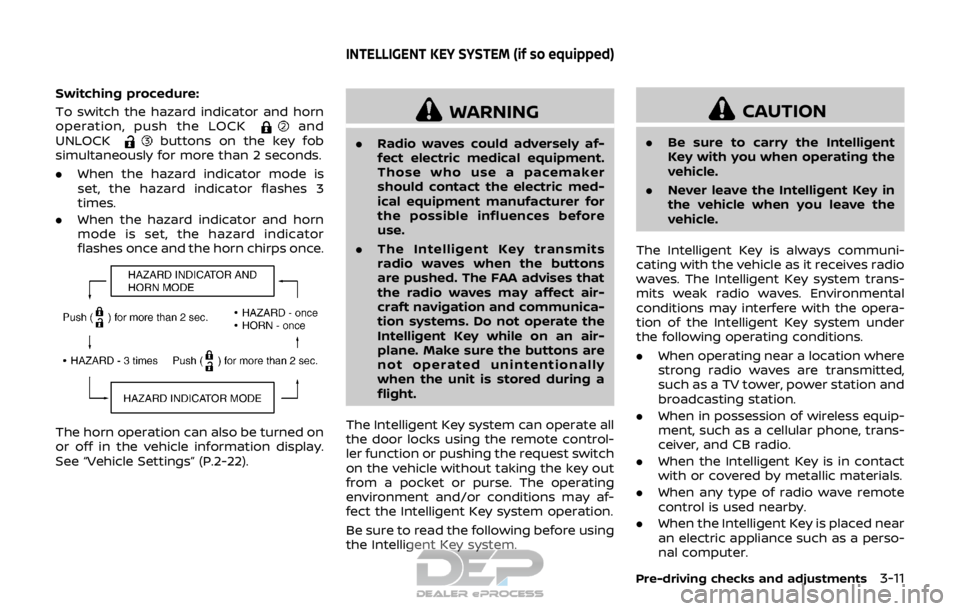
Switching procedure:
To switch the hazard indicator and horn
operation, push the LOCK
and
UNLOCKbuttons on the key fob
simultaneously for more than 2 seconds.
. When the hazard indicator mode is
set, the hazard indicator flashes 3
times.
. When the hazard indicator and horn
mode is set, the hazard indicator
flashes once and the horn chirps once.
The horn operation can also be turned on
or off in the vehicle information display.
See “Vehicle Settings” (P.2-22).
WARNING
.Radio waves could adversely af-
fect electric medical equipment.
Those who use a pacemaker
should contact the electric med-
ical equipment manufacturer for
the possible influences before
use.
. The Intelligent Key transmits
radio waves when the buttons
are pushed. The FAA advises that
the radio waves may affect air-
craft navigation and communica-
tion systems. Do not operate the
Intelligent Key while on an air-
plane. Make sure the buttons are
not operated unintentionally
when the unit is stored during a
flight.
The Intelligent Key system can operate all
the door locks using the remote control-
ler function or pushing the request switch
on the vehicle without taking the key out
from a pocket or purse. The operating
environment and/or conditions may af-
fect the Intelligent Key system operation.
Be sure to read the following before using
the Intelligent Key system.
CAUTION
. Be sure to carry the Intelligent
Key with you when operating the
vehicle.
. Never leave the Intelligent Key in
the vehicle when you leave the
vehicle.
The Intelligent Key is always communi-
cating with the vehicle as it receives radio
waves. The Intelligent Key system trans-
mits weak radio waves. Environmental
conditions may interfere with the opera-
tion of the Intelligent Key system under
the following operating conditions.
. When operating near a location where
strong radio waves are transmitted,
such as a TV tower, power station and
broadcasting station.
. When in possession of wireless equip-
ment, such as a cellular phone, trans-
ceiver, and CB radio.
. When the Intelligent Key is in contact
with or covered by metallic materials.
. When any type of radio wave remote
control is used nearby.
. When the Intelligent Key is placed near
an electric appliance such as a perso-
nal computer.
Pre-driving checks and adjustments3-11
INTELLIGENT KEY SYSTEM (if so equipped)
Page 168 of 512

3. Within 5 seconds push and hold theremote engine startbutton until
the turn signal lights flash and the tail
lights illuminate. If the vehicle is not
within view, push and hold the remote
engine start
button for at least 2
seconds.
The following events will occur when the
engine starts:
. The front parking lights will turn on
and remain on as long as the engine is
running.
. The doors will be locked and the air
conditioner system may turn on.
. The engine will continue to run for
about 10 minutes. Repeat the steps to
extend the time for an additional 10
minutes. See “Extending engine run
time” (P.3-23).
Depress and hold the brake pedal, then
place the ignition switch in the ON posi-
tion before driving. For further instruc-
tions, see “Driving the vehicle” (P.5-20).
EXTENDING ENGINE RUN TIME
The remote engine start function can be
extended one time by performing the
steps listed in “Remote starting the en-
gine” (P.3-22). Run time will be calculated
as follows:
. The first 10 minute run time will start
when the remote engine start func- tion is performed.
. The second 10 minutes will start im-
mediately when the remote engine
start function is performed. For exam-
ple, if the engine has been running for
5 minutes, and 10 minutes are added,
the engine will run for a total of 15
minutes.
. Extending engine run time will count
towards the two remote start limit.
A maximum of two remote starts, or a
single start with an extension, are allowed
between ignition cycles.
The ignition switch must be cycled to the
ON position and then back to the OFF
position before the remote engine start
procedure can be used again.
CANCELING A REMOTE START
To cancel a remote start, perform one of
the following:
. Aim the Intelligent Key at the vehicle
and push and hold the remote engine
start
button until the front park-
ing lights turn off.
. Turn on the hazard indicator flashers.
. Cycle the ignition switch ON and then
OFF.
. The extended engine run time has
expired. .
The first 10 minute timer has expired.
. The engine hood has been opened.
. The shift lever is moved out of the P
(Park) position.
. The theft alarm sounds due to illegal
entry into the vehicle.
. The ignition switch is pushed without
an Intelligent Key in the vehicle.
. The ignition switch is pushed with an
Intelligent Key in the vehicle but the
brake pedal is not depressed.
CONDITIONS THE REMOTE ENGINE
START WILL NOT WORK
The remote engine start will not operate
if any of the following conditions are
present:
.The ignition switch is placed in the ON
position.
. The hood is not securely closed.
. The hazard indicator flashers are on.
. The engine is still running. The engine
must be completely stopped. Wait at
least 6 seconds if the engine goes
from running to off. This is not applic-
able when extending engine run time.
. The remote engine start
button is
not pushed and held for at least 2
seconds.
. The remote engine start
button is
not pushed and held within 5 seconds
Pre-driving checks and adjustments3-23