ad blue NISSAN ROGUE SPORT 2019 Owners Manual
[x] Cancel search | Manufacturer: NISSAN, Model Year: 2019, Model line: ROGUE SPORT, Model: NISSAN ROGUE SPORT 2019Pages: 500, PDF Size: 2.37 MB
Page 14 of 500
0-6Illustrated table of contents
WAA0056X
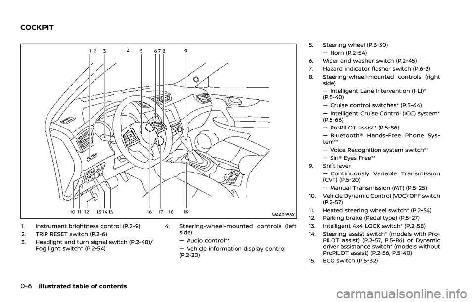
1. Instrument brightness control (P.2-9)
2. TRIP RESET switch (P.2-6)
3. Headlight and turn signal switch (P.2-48)/Fog light switch* (P.2-54) 4. Steering-wheel-mounted controls (left
side)
— Audio control**
— Vehicle information display control
(P.2-20) 5. Steering wheel (P.3-30)
— Horn (P.2-54)
6. Wiper and washer switch (P.2-45)
7. Hazard indicator flasher switch (P.6-2)
8. Steering-wheel-mounted controls (right side)
— Intelligent Lane Intervention (I-LI)*
(P.5-40)
— Cruise control switches* (P.5-64)
— Intelligent Cruise Control (ICC) system*
(P.5-66)
— ProPILOT assist* (P.5-86)
— Bluetooth® Hands-Free Phone Sys-
tem**
— Voice Recognition system switch**
— Siri® Eyes Free**
9. Shift lever
— Continuously Variable Transmission
(CVT) (P.5-20)
— Manual Transmission (MT) (P.5-25)
10. Vehicle Dynamic Control (VDC) OFF switch (P.2-57)
11. Heated steering wheel switch* (P.2-54)
12. Parking brake (Pedal type) (P.5-27)
13. Intelligent 4x4 LOCK switch* (P.2-58)
14. Steering assist switch* (models with Pro- PILOT assist) (P.2-57, P.5-86) or Dynamic
driver assistance switch* (models without
ProPILOT assist) (P.2-56, P.5-40)
15. ECO switch (P.5-32)
COCKPIT
Page 16 of 500
0-8Illustrated table of contents
JVC1090X
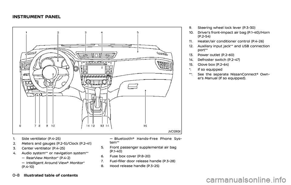
1. Side ventilator (P.4-25)
2. Meters and gauges (P.2-5)/Clock (P.2-41)
3. Center ventilator (P.4-25)
4. Audio system** or navigation system**— RearView Monitor* (P.4-2)
— Intelligent Around View® Monitor*
(P.4-10) — Bluetooth® Hands-Free Phone Sys-
tem**
5. Front passenger supplemental air bag (P.1-40)
6. Fuse box cover (P.8-20)
7. Fuel-filler door release handle (P.3-28)
8. Hood release handle (P.3-25) 9. Steering wheel lock lever (P.3-30)
10. Driver’s front-impact air bag (P.1-40)/Horn
(P.2-54)
11. Heater/air conditioner control (P.4-26)
12. Auxiliary input jack** and USB connection port**
13. Power outlet (P.2-60)
14. Defroster switch (P.2-47)
15. Glove box (P.2-64)
*: if so equipped
**: See the separate NissanConnect® Own- er’s Manual (if so equipped).
INSTRUMENT PANEL
Page 83 of 500
WAA0056X
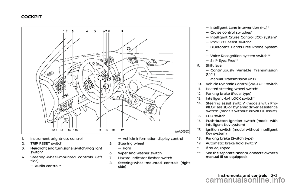
1. Instrument brightness control
2. TRIP RESET switch
3. Headlight and turn signal switch/Fog lightswitch*
4. Steering-wheel-mounted controls (left side)
— Audio control** — Vehicle information display control
5. Steering wheel — Horn
6. Wiper and washer switch
7. Hazard indicator flasher switch
8. Steering-wheel-mounted controls (right side) — Intelligent Lane Intervention (I-LI)*
— Cruise control switches*
— Intelligent Cruise Control (ICC) system*
— ProPILOT assist switch*
— Bluetooth® Hands-Free Phone System
**
— Voice Recognition system switch**
— Siri® Eyes Free**
9. Shift lever — Continuously Variable Transmission
(CVT)
— Manual Transmission (MT)
10. Vehicle Dynamic Control (VDC) OFF switch
11. Heated steering wheel switch*
12. Parking brake (Pedal type)
13. Intelligent 4x4 LOCK switch*
14. Steering assist switch* (models with Pro- PILOT assist) or Dynamic driver assistance
switch* (models without ProPILOT assist)
15. ECO switch
16. Push-button ignition switch (model with Intelligent Key system)
17. Ignition switch (model without Intelligent Key system)
18. Parking brake (Switch type)
19. Automatic brake hold switch*
*: if so equipped
**: See the separate NissanConnect® owner’s manual (if so equipped).
Instruments and controls2-3
COCKPIT
Page 84 of 500
2-4Instruments and controls
JVC1090X
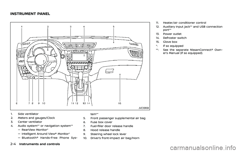
1. Side ventilator
2. Meters and gauges/Clock
3. Center ventilator
4. Audio system** or navigation system**— RearView Monitor*
— Intelligent Around View® Monitor*
— Bluetooth® Hands-Free Phone Sys- tem**
5. Front passenger supplemental air bag
6. Fuse box cover
7. Fuel-filler door release handle
8. Hood release handle
9. Steering wheel lock lever
10. Driver’s front-impact air bag/Horn 11. Heater/air conditioner control
12. Auxiliary input jack** and USB connection
port**
13. Power outlet
14. Defroster switch
15. Glove box
*: if so equipped
**: See the separate NissanConnect® Own- er’s Manual (if so equipped).
INSTRUMENT PANEL
Page 217 of 500
JVH1257X
Rear and front-side views
WAE0067XRear view
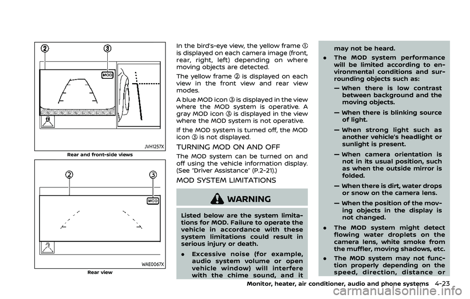
In the bird’s-eye view, the yellow frameis displayed on each camera image (front,
rear, right, left) depending on where
moving objects are detected.
The yellow frame
is displayed on each
view in the front view and rear view
modes.
A blue MOD icon
is displayed in the view
where the MOD system is operative. A
gray MOD icon
is displayed in the view
where the MOD system is not operative.
If the MOD system is turned off, the MOD
icon
is not displayed.
TURNING MOD ON AND OFF
The MOD system can be turned on and
off using the vehicle information display.
(See “Driver Assistance” (P.2-21).)
MOD SYSTEM LIMITATIONS
WARNING
Listed below are the system limita-
tions for MOD. Failure to operate the
vehicle in accordance with these
system limitations could result in
serious injury or death.
. Excessive noise (for example,
audio system volume or open
vehicle window) will interfere
with the chime sound, and it may not be heard.
. The MOD system performance
will be limited according to en-
vironmental conditions and sur-
rounding objects such as:
— When there is low contrast
between background and the
moving objects.
— When there is blinking source of light.
— When strong light such as another vehicle’s headlight or
sunlight is present.
— When camera orientation is not in its usual position, such
as when the outside mirror is
folded.
— When there is dirt, water drops or snow on the camera lens.
— When the position of the mov- ing objects in the display is
not changed.
. The MOD system might detect
flowing water droplets on the
camera lens, white smoke from
the muffler, moving shadows, etc.
. The MOD system may not func-
tion properly depending on the
speed, direction, distance or
Monitor, heater, air conditioner, audio and phone systems4-23
Page 218 of 500
4-24Monitor, heater, air conditioner, audio and phone systems
shape of the moving objects.
. If your vehicle sustains damage
to the parts where the camera is
installed, leaving it misaligned or
bent, the sensing zone may be
altered and the MOD system may
not detect objects properly.
. When the temperature is extre-
mely high or low, the screen may
not display objects clearly. This is
not a malfunction.
NOTE:
The blue MOD icon will change to
orange if one of the following has
occurred.
. When the system is malfunctioning.
. When the component temperature
reaches a high level (icon will blink).
. When the rear view camera has
detected a blockage (icon will blink).
If the icon light continues to illuminate
orange, have the MOD system checked.
It is recommended that you visit a
NISSAN dealer for this service.
WAE0059X
SYSTEM MAINTENANCE
CAUTION
. Do not use alcohol, benzine or
thinner to clean the camera. This
will cause discoloration.
. Do not damage the camera as the
monitor screen may be adversely
affected.
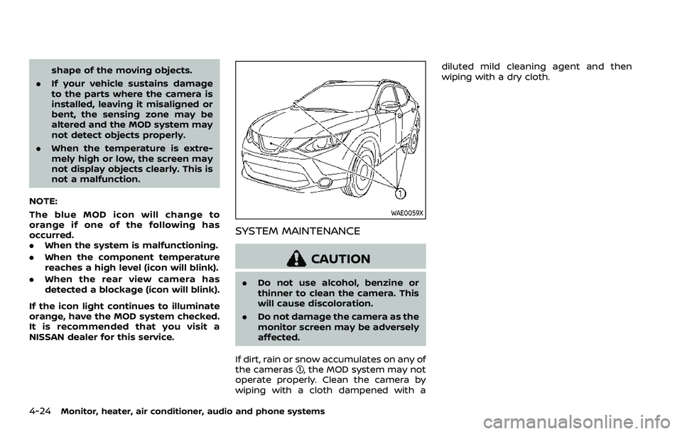
If dirt, rain or snow accumulates on any of
the cameras
, the MOD system may not
operate properly. Clean the camera by
wiping with a cloth dampened with a diluted mild cleaning agent and then
wiping with a dry cloth.
Page 244 of 500
5-16Starting and driving
Continuously Variable Transmis-
sion (CVT) models
The ignition lock is designed so that the
ignition switch position cannot be
switched to OFF until the shift lever is
moved to the P (Park) position.
When the ignition switch cannot be
pushed toward the OFF position, proceed
as follows:
1. Move the shift lever into the P (Park)position.
2. Push the ignition switch. The ignition switch position will change to the ON
position.
3. Push the ignition switch again to the OFF position.
The shift lever can be moved from the P
(Park) position if the ignition switch is in
the ON position and the brake pedal is
depressed.
PUSH-BUTTON IGNITION SWITCH
POSITIONS
LOCK (Normal parking position)
The ignition switch can only be locked at
this position.
The ignition switch will lock when any
door is opened or closed with the ignition
switched off.
ON (Normal operating position)
The ignition system and the electrical
accessory power activate at this position
without the engine turned on.
The ON position has a battery saver
feature that will place the ignition switch
in the OFF position, if the vehicle is not
running, after some time under the fol-
lowing conditions:
. all doors are closed.
. shift lever is in P (Park) position (CVT
model) or N (Neutral) position (MT
model).
The battery saver feature will be can-
celled if any of the following occur:
. any door is opened.
. shift lever is moved out of the P (Park)
position (CVT model). .
ignition switch changes position.
OFF position
The engine is turned off in this position.
Auto ACC position
With the vehicle in the P (Park) position
(CVT models) or the N (Neutral) position
(MT models), the Intelligent Key with you
and the ignition placed from ON to OFF,
the radio can still be used for a period of
time, or until the driver’s door is opened.
After a period of time, functions such as
radio, navigation (if so equipped), and
Bluetooth® Hands-Free Phone System
may be restarted by turning on the audio
system (see the separate NissanConnect®
Owner’s Manual), or by pushing the UN-
LOCK button on the Intelligent Key for up
to a total of 30 minutes.
EMERGENCY ENGINE SHUT OFF
To shut off the engine in an emergency
situation while driving, perform the fol-
lowing procedure:
.Rapidly push the push-button ignition
switch 3 consecutive times in less
than 1.5 seconds, or
. Push and hold the push-button igni-
tion switch for more than 2 seconds.
Page 319 of 500
assist system by the color of the
indicator
.ProPILOT assist status indicator(white): ProPILOT assist is on but
in standby.
.ProPILOT assist status indicator(blue): ProPILOT assist active
TURNING THE CONVENTIONAL
(fixed speed) CRUISE CONTROL
MODE ON
NOTE:
ProPILOT assist provides no approach
warnings, automatic braking, or steer-
ing assist in the conventional (fixed
speed) cruise control mode.
To choose the conventional (fixed speed)
cruise control mode, push and hold the
ProPILOT assist switch for longer than
approximately 1.5 seconds. For additional
information, see “Conventional (fixed
speed) cruise control mode” (P.5-112).
WAF0050X
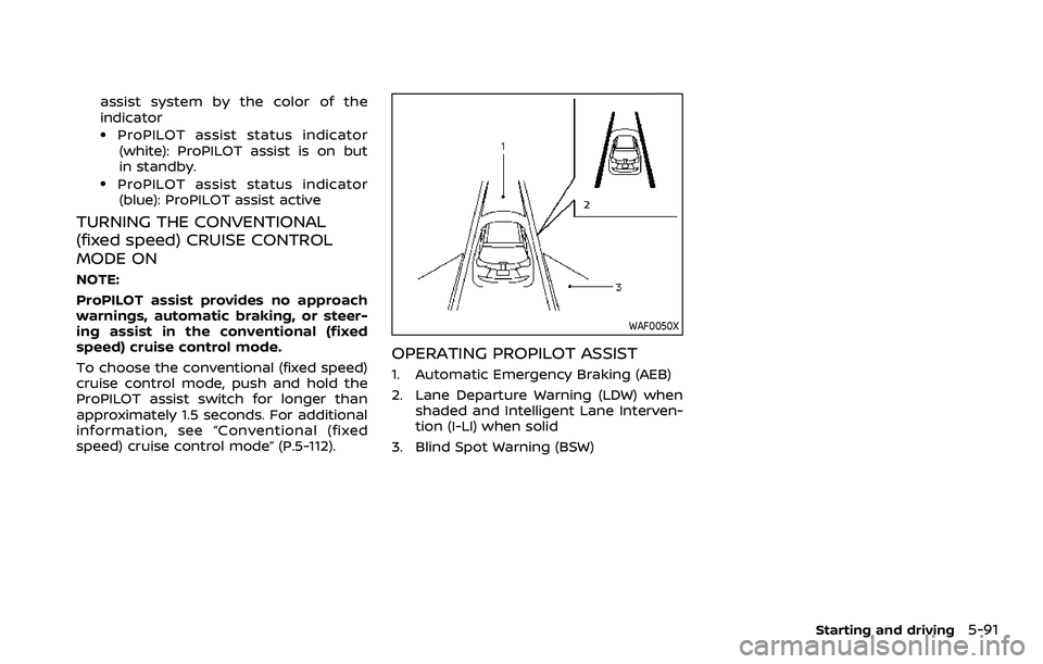
OPERATING PROPILOT ASSIST
1. Automatic Emergency Braking (AEB)
2. Lane Departure Warning (LDW) when shaded and Intelligent Lane Interven-
tion (I-LI) when solid
3. Blind Spot Warning (BSW)
Starting and driving5-91
Page 320 of 500
5-92Starting and driving
WAF0051X
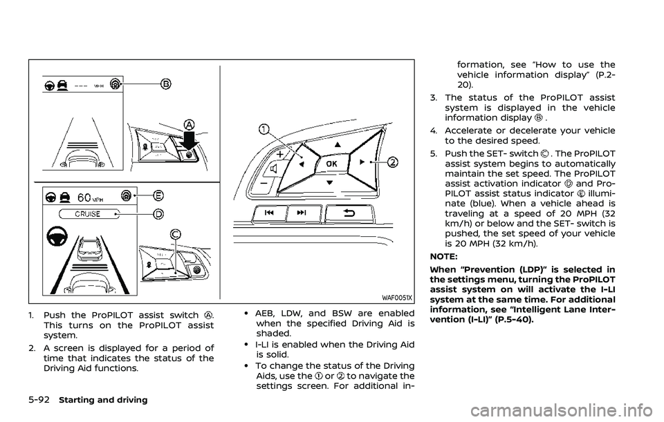
1. Push the ProPILOT assist switch.
This turns on the ProPILOT assist
system.
2. A screen is displayed for a period of time that indicates the status of the
Driving Aid functions..AEB, LDW, and BSW are enabledwhen the specified Driving Aid is
shaded.
.I-LI is enabled when the Driving Aid is solid.
.To change the status of the DrivingAids, use theorto navigate the
settings screen. For additional in- formation, see “How to use the
vehicle information display” (P.2-
20).
3. The status of the ProPILOT assist system is displayed in the vehicle
information display
.
4. Accelerate or decelerate your vehicle to the desired speed.
5. Push the SET- switch
. The ProPILOT
assist system begins to automatically
maintain the set speed. The ProPILOT
assist activation indicator
and Pro-
PILOT assist status indicatorillumi-
nate (blue). When a vehicle ahead is
traveling at a speed of 20 MPH (32
km/h) or below and the SET- switch is
pushed, the set speed of your vehicle
is 20 MPH (32 km/h).
NOTE:
When “Prevention (LDP)” is selected in
the settings menu, turning the ProPILOT
assist system on will activate the I-LI
system at the same time. For additional
information, see “Intelligent Lane Inter-
vention (I-LI)” (P.5-40).
Page 416 of 500
8-4Do-it-yourself
JVC1070X
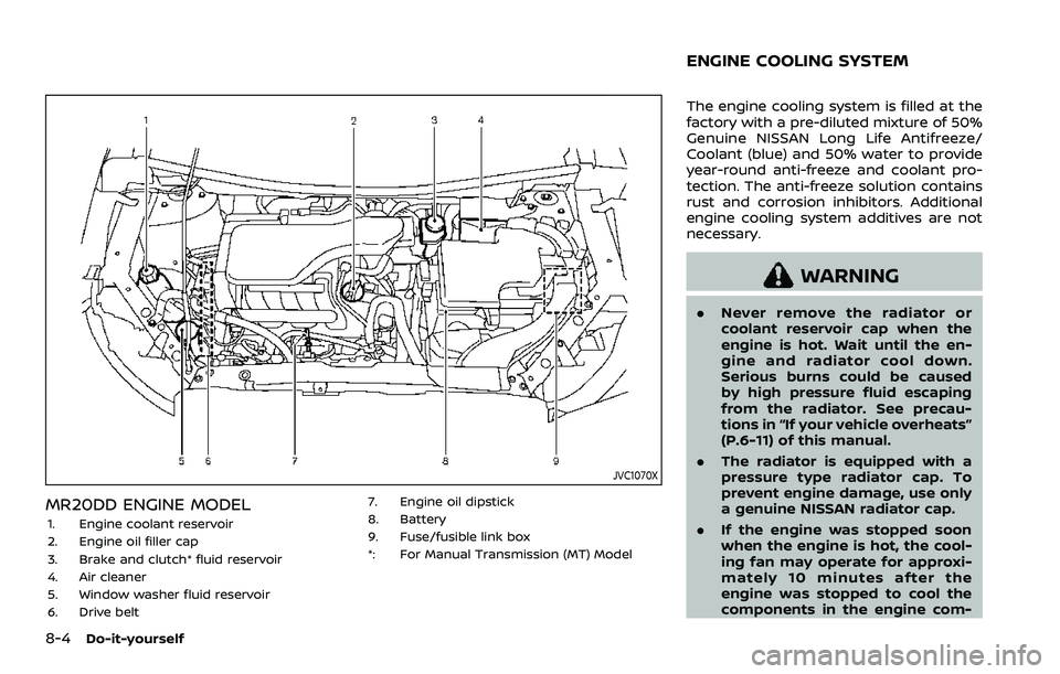
MR20DD ENGINE MODEL
1. Engine coolant reservoir
2. Engine oil filler cap
3. Brake and clutch* fluid reservoir
4. Air cleaner
5. Window washer fluid reservoir
6. Drive belt7. Engine oil dipstick
8. Battery
9. Fuse/fusible link box
*: For Manual Transmission (MT) Model
The engine cooling system is filled at the
factory with a pre-diluted mixture of 50%
Genuine NISSAN Long Life Antifreeze/
Coolant (blue) and 50% water to provide
year-round anti-freeze and coolant pro-
tection. The anti-freeze solution contains
rust and corrosion inhibitors. Additional
engine cooling system additives are not
necessary.
WARNING
.
Never remove the radiator or
coolant reservoir cap when the
engine is hot. Wait until the en-
gine and radiator cool down.
Serious burns could be caused
by high pressure fluid escaping
from the radiator. See precau-
tions in “If your vehicle overheats”
(P.6-11) of this manual.
. The radiator is equipped with a
pressure type radiator cap. To
prevent engine damage, use only
a genuine NISSAN radiator cap.
. If the engine was stopped soon
when the engine is hot, the cool-
ing fan may operate for approxi-
mately 10 minutes after the
engine was stopped to cool the
components in the engine com-
ENGINE COOLING SYSTEM