battery NISSAN ROGUE SPORT 2021 Owners Manual
[x] Cancel search | Manufacturer: NISSAN, Model Year: 2021, Model line: ROGUE SPORT, Model: NISSAN ROGUE SPORT 2021Pages: 516, PDF Size: 2.43 MB
Page 17 of 516

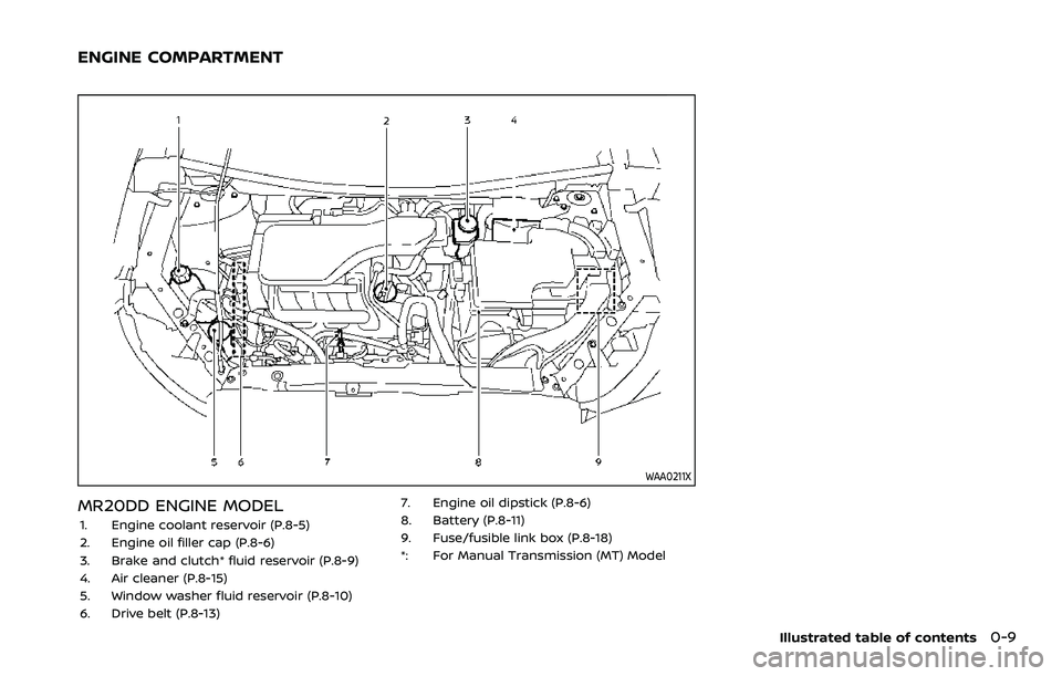
WAA0211X
MR20DD ENGINE MODEL
1. Engine coolant reservoir (P.8-5)
2. Engine oil filler cap (P.8-6)
3. Brake and clutch* fluid reservoir (P.8-9)
4. Air cleaner (P.8-15)
5. Window washer fluid reservoir (P.8-10)
6. Drive belt (P.8-13)7. Engine oil dipstick (P.8-6)
8. Battery (P.8-11)
9. Fuse/fusible link box (P.8-18)
*: For Manual Transmission (MT) Model
Illustrated table of contents0-9
ENGINE COMPARTMENT
Page 23 of 516

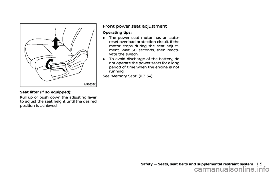
JVR0333X
Seat lifter (if so equipped):
Pull up or push down the adjusting lever
to adjust the seat height until the desired
position is achieved.
Front power seat adjustment
Operating tips:
.The power seat motor has an auto-
reset overload protection circuit. If the
motor stops during the seat adjust-
ment, wait 30 seconds, then reacti-
vate the switch.
. To avoid discharge of the battery, do
not operate the power seats for a long
period of time when the engine is not
running.
See “Memory Seat” (P.3-34).
Safety — Seats, seat belts and supplemental restraint system1-5
Page 113 of 516

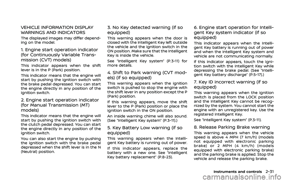
VEHICLE INFORMATION DISPLAY
WARNINGS AND INDICATORS
The displayed images may differ depend-
ing on the model.
1. Engine start operation indicator
(for Continuously Variable Trans-
mission (CVT) models)
This indicator appears when the shift
lever is in the P (Park) position.
This indicator means that the engine will
start by pushing the ignition switch with
the brake pedal depressed. You can start
the engine directly in any position of the
ignition switch.
2. Engine start operation indicator
(for Manual Transmission (MT)
models)
This indicator means that the engine will
start by pushing the ignition switch with
the clutch pedal depressed. You can start
the engine directly in any position of the
ignition switch.
You can also start the engine by pushing
the ignition switch with the brake pedal
depressed when the shift lever is in the N
(Neutral) position.
3. No Key detected warning (if so
equipped)
This warning appears when the door is
closed with the Intelligent Key left outside
the vehicle and the ignition switch in the
ON position. Make sure that the Intelligent
Key is inside the vehicle.
See “Intelligent Key system” (P.3-11) for
more details.
4. Shift to Park warning (CVT mod-
els) (if so equipped)
This warning appears when the ignition
switch is pushed to stop the engine with
the shift lever in any position except the P
(Park) position.
If this warning appears, move the shift
lever to the P (Park) position or place the
ignition switch in the ON position.
An inside warning chime will also sound.
(See “Intelligent Key system” (P.3-11).)
5. Key Battery Low warning (if so
equipped)
This warning appears when the Intelli-
gent Key battery is running out of power.
If this indicator appears, replace the
battery with a new one. See “Intelligent
Key battery replacement” (P.8-23).
6. Engine start operation for Intelli-
gent Key system indicator (if so
equipped)
This indicator appears when the Intelli-
gent Key battery is running out of power
and when the Intelligent Key system and
vehicle are not communicating normally.
If this indicator appears, touch the igni-
tion switch with the Intelligent Key while
depressing the brake pedal. (See “Intelli-
gent Key battery discharge” (P.5-17).)
7. Key ID incorrect warning (if so
equipped)
This warning appears when the ignition
switch is placed from the LOCK position
and the Intelligent Key cannot be recog-
nized by the system. You cannot start the
engine with an unregistered key. Use the
registered Intelligent Key.
See “Intelligent Key system” (P.3-11).
8. Release Parking Brake warning
This warning appears when the vehicle
speed is above 4 MPH (7 km/h) (models
not equipped with electronic parking
brake) or 2 MPH (4 km/h) (models
equipped with electronic parking brake)
and the parking brake is applied. Stop the
vehicle and release the parking brake.
Instruments and controls2-31
Page 115 of 516

CAUTION
Running the engine with the engine
oil pressure warning displayed could
cause serious damage to the engine.
17. AWD Error: See Owner’s Manual
warning (if so equipped)
This warning appears when the All-Wheel
Drive (AWD) system is not functioning
properly while the engine is running.
Reduce vehicle speed and have the sys-
tem checked. It is recommended that you
visit a NISSAN dealer for this service. See
“Intelligent 4x4” (P.5-123).
18. AWD High Temp. Stop vehicle
warning (if so equipped)
This warning may appear while trying to
free a stuck vehicle due to increased oil
temperature. The driving mode may
change to Two-Wheel Drive (2WD). If this
warning is displayed, stop the vehicle with
the engine idling, as soon as it is safe to
do so. Then if the warning turns off, you
can continue driving. See “Intelligent 4x4”
(P.5-123).
19. Tire Size Incorrect: See Owner’s
Manual warning (if so equipped)
This warning may appear if there is a
large difference between the diameters of
the front and rear wheels and tires. Pull
off the road in a safe area, with the engine
idling. Check that all the tire sizes are the
same, that the tire pressure is correct and
that the tires are not excessively worn.
See “Intelligent 4x4” (P.5-123).
20. Battery Voltage Low Charge
Battery warning
This warning appears when the battery
voltage is low and the battery needs to be
charged.
21. Shipping Mode On Push Storage
Fuse warning (if so equipped)
This warning may appear if the extended
storage fuse switch is not pushed in
(switched on). When this warning ap-
pears, push in (switch on) the extended
storage fuse switch to turn off the warn-
ing. For more information, see “Extended
storage fuse switch” (P.8-21).
22. Power will turn off to save the
battery warning
This warning appears after the ignition
switch is in the ON position for a certain
period of time.
23. Power turned off to save the
battery warning
This warning appears after the ignition
switch is automatically turned OFF to
save the battery.
24. Reminder: Turn OFF Headlights
warning
This warning appears when the driver
side door is opened with the headlight
switch is left ON and the ignition switch is
placed in the OFF or LOCK position. Place
the headlight switch in OFF (if so
equipped) or AUTO position. For addi-
tional information, see “Headlight and
turn signal switch” (P.2-52).
25. Headlight System Error: See
Owner’s Manual warning (if so
equipped)
This warning appears if the LED head-
lights are malfunctioning. Have the sys-
tem checked. It is recommended that you
visit a NISSAN dealer for this service.
Instruments and controls2-33
Page 129 of 516

.Opening any doors, the hood (if so
equipped) or liftgate without using the
key or Intelligent Key (even if the door
is unlocked by releasing the door
inside lock knob or using the mechan-
ical key).
How to stop an activated alarm
The alarm stops only by unlocking a door
or the liftgate by pushing the UNLOCK
button on the key fob (if so equipped)
or the Intelligent Key (if so equipped), or
pushing the request switch (if so
equipped) on the driver’s or passenger’s
door in range of the door handle.
If the Intelligent Key battery is dis-
charged:
If the Intelligent Key battery is discharged,
the alarm will not stop by pushing the
UNLOCK
button on the key fob (if so
equipped) or the Intelligent Key (if so
equipped), or pushing the request switch
(if so equipped) on the driver’s or passen-
ger’s door in range of the door handle. In
such a case, unlock the driver’s door
using the mechanical key and touch the
ignition switch with the Intelligent Key to
stop the alarm. (See “Intelligent Key bat-
tery discharge” (P.5-17).)
NISSAN VEHICLE IMMOBILIZER SYS-
TEM
The NISSAN Vehicle Immobilizer System
will not allow the engine to start without
the use of the registered key.
If the engine fails to start using the
registered key, it may be due to inter-
ference caused by another registered key,
an automated toll road device or auto-
mated payment device on the key ring.
Restart the engine using the following
procedures:
1. Leave the ignition switch in the ON position for approximately 5 seconds.
2. Place the ignition switch in the OFF or LOCK position and wait approximately
10 seconds.
3. Repeat step 1 and 2 again.
4. Restart the engine while holding the device (which may have caused the
interference) separate from the regis-
tered key.
If this procedure allows the engine to
start, NISSAN recommends placing the
registered key on a separate key ring
to avoid interference from other de-
vices.
Statement related to section 15 of FCC
rules for NISSAN Vehicle Immobilizer
System (CONT ASSY-BCM. ANT ASSY- IMMOBILISER)
FCC Notice:
For USA:
This device complies with Part 15 of the
FCC Rules. Operation is subject to the
following two conditions: (1) This device
may not cause harmful interference,
and (2) this device must accept any
interference received, including inter-
ference that may cause undesired op-
eration.
Note: Changes or modifications not
expressly approved by the party re-
sponsible for compliance could void
the user’s authority to operate the
equipment.
For Canada:
This device complies with Industry Ca-
nada licence-exempt RSS standard(s).
Operation is subject to the following
two conditions: (1) this device may not
cause interference, and (2) this device
must accept any interference, including
interference that may cause undesired
operation of the device.
Instruments and controls2-47
Page 139 of 516

WAC0198X
Ambient image sensor maintenance:
The ambient image sensor
for the high
beam assist system is located in front of
the inside mirror. To keep the proper
operation of the high beam assist system
and prevent a system malfunction, be
sure to observe the following:
. Always keep the windshield clean.
. Do not attach a sticker (including
transparent material) or install an
accessory near the ambient image
sensor.
. Do not strike or damage the areas
around the ambient image sensor. Do
not touch the sensor lens that is
located on the ambient image sensor. If the ambient image sensor is damaged
due to an accident, it is recommended
you contact a NISSAN dealer.
Battery saver system
.
When the headlight switch is in theorposition while the ignition
switch is in the ON position, the lights
will automatically turn off within a
period of time after the ignition switch
has been placed in the OFF position.
. When the headlight switch remains in
the
orposition after the lights
automatically turn off, the lights will
turn on when the ignition switch is
placed in the ON position.
CAUTION
. When you turn on the headlight
switch again after the lights auto-
matically turn off, the lights will
not turn off automatically. Be
sure to turn the light switch to
the OFF (if so equipped) or the
AUTO position when you leave
the vehicle for extended periods
of time, otherwise the battery will
be discharged.
. Never leave the light switch on
when the engine is not running for extended periods of time even
if the headlights turn off auto-
matically.
Daytime Running Light (DRL) sys-
tem
Type A:
The LED portion of the headlights auto-
matically illuminate at 100% intensity
when the engine is started and the
parking brake released. The LED Daytime
Running Light (DRL) operate with the
headlight switch in the OFF position or
in the
position. When you turn the
headlight switch to theposition for
full illumination, the LED lights switch
from LED DRL to the park function.
If the parking brake is applied before the
engine is started, the LED DRL do not
illuminate. The LED DRL illuminate when
the parking brake is released. The LED
DRL will remain on until the ignition
switch is placed in the OFF position.
It is necessary at dusk to turn the head-
light switch ON for interior controls and
switches to illuminate, as those remain
OFF while the switch is in the OFF
position.
Instruments and controls2-57
Page 142 of 516

2-60Instruments and controls
indicator light will turn off.
NOTE:
If the surface temperature of the steer-
ing wheel is above 68°F (20°C) when the
switch is turned on, the system will not
heat the steering wheel. This is not a
malfunction.
WARNING
Do not use or allow occupants to use
the seat heater if you or the occu-
pants cannot monitor elevated seat
temperatures or have an inability to
feel pain in body parts that contact
the seat. Use of the seat heater by
such people could result in serious
injury.
CAUTION
.The battery could run down if the
seat heater is operated while the
engine is not running.
. Do not use the seat heater for
extended periods or when no one
is using the seat.
. Do not put anything on the seat
which insulates heat, such as a
blanket, cushion, seat cover, etc.
Otherwise, the seat may become
overheated.
. Do not place anything hard or
heavy on the seat or pierce it with
a pin or similar object. This may
result in damage to the heater. .
Any liquid spilled on the heated
seat should be removed immedi-
ately with a dry cloth.
. When cleaning the seat, never use
gasoline, thinner, or any similar
materials.
. If any malfunctions are found or
the heated seat does not operate,
turn the switch off and have the
system checked. It is recom-
mended you visit a NISSAN dealer
for this service.
HEATED SEATS (if so equipped)
Page 147 of 516

system.
. The ECO mode system will turn off
automatically if a malfunction occurs
in the system.
. Turn off the ECO mode system when
acceleration is required such as when:
— driving with a heavy load of pas-
sengers or cargo in the vehicle
— driving on a steep uphill slope
WAC0077X
Instrument Panel
WAC0233XCenter Console Box
The power outlet is located in the instru-
ment panel and center console box.
CAUTION
. The outlet and plug may be hot
during or immediately after use.
. Do not use with accessories that
exceed a 12 volt, 120W (10A)
power draw. Do not use double
adapters or more than one elec-
trical accessory.
. Use power outlet with the engine
running to avoid discharging the
vehicle battery.
. Avoid using power outlet when
the air conditioner, headlights or
rear window defroster is on.
. This power outlet is not designed
for use with a cigarette lighter
unit.
. Push the plug in as far as it will
go. If good contact is not made,
the plug may overheat or the
internal temperature fuse may
open.
. Before inserting or disconnecting
a plug, be sure the electrical
accessory being used is turned
OFF.
Instruments and controls2-65
POWER OUTLET
Page 162 of 516

2-80Instruments and controls
matically when the auto reverse function
activates due to a malfunction, push and
hold the moonroof switch to the close
position
.
Depending on the environment or driv-
ing conditions, the auto reverse func-
tion may be activated if an impact or
load similar to something being caught
in the moonroof occurs.
If the moonroof does not operate
If the moonroof does not operate prop-
erly, perform the following procedure to
initialize the moonroof operation system.
1. If the moonroof is open, close it fully by repeatedly pushing the moonroof
switch to the close position
to tilt
the moonroof up.
2. Push and hold the switch to the close position
.
3. Release the moonroof switch after the moonroof moves slightly up and
down.
4. Push and hold the switch to the open position
to fully tilt the moonroof
down.
5. Check if the moonroof switch oper- ates normally.
If the moonroof does not operate prop-
erly after performing the procedure
above, have your moonroof checked and repaired. It is recommended you visit a
NISSAN dealer for this service.
CAUTION
.
Do not leave the light switch on
when the engine is not running
for extended periods of time to
prevent the battery from being
discharged.
. Turn off the lights when you leave
the vehicle.
INTERIOR LIGHTS
Page 164 of 516

2-82Instruments and controls
SIC2063A
ROOM LIGHT
The room light has a three-position
switch.
When the switch is in the ON position
,
the room light illuminates.
When the switch is in the DOOR position
, the room light illuminates when a door
is opened.
The interior light timer will keep the room
light on for approximately 15 seconds
when:
. The key is removed from the ignition
switch with the driver’s door closed.
(model without Intelligent Key system) .
The ignition switch is placed in the
OFF position. (model with Intelligent
Key system)
The interior light timer will be cancelled
when:
. The driver’s door is locked.
. The ignition switch is placed in the ON
position.
When the switch is in the OFF position
,
the room light does not illuminate, re-
gardless of any condition.
SIC3869
VANITY MIRROR LIGHT (if so
equipped)
The light on the vanity mirror will turn on
when the cover on the vanity mirror is
opened.
When the cover is closed, the light will
turn off.
The lights will also turn off after a
period of time when the lights remain
illuminated to prevent the battery from
becoming discharged.