rear view mirror NISSAN ROGUE SPORT 2021 Owners Manual
[x] Cancel search | Manufacturer: NISSAN, Model Year: 2021, Model line: ROGUE SPORT, Model: NISSAN ROGUE SPORT 2021Pages: 516, PDF Size: 2.43 MB
Page 13 of 516
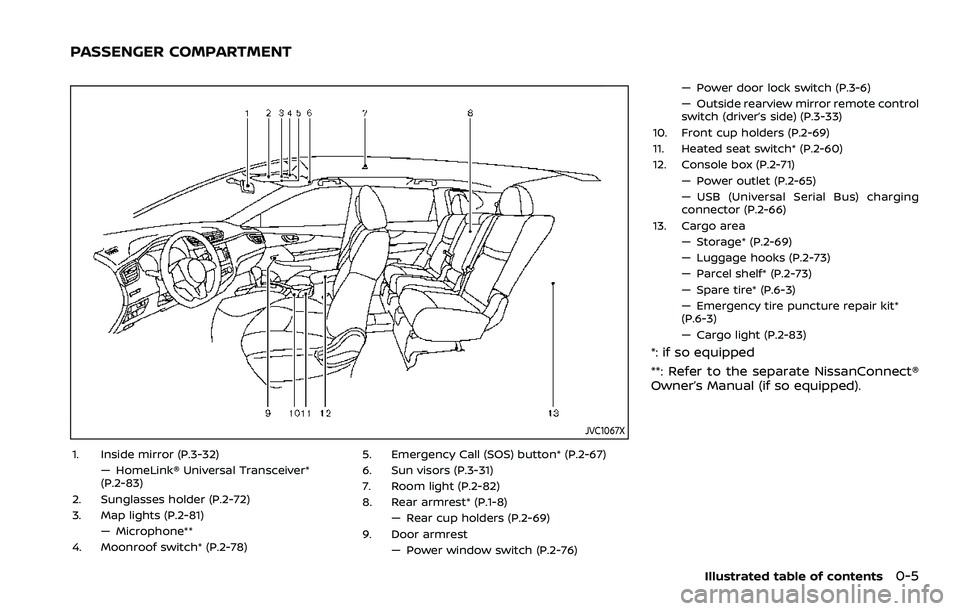
JVC1067X
1. Inside mirror (P.3-32)— HomeLink® Universal Transceiver*
(P.2-83)
2. Sunglasses holder (P.2-72)
3. Map lights (P.2-81) — Microphone**
4. Moonroof switch* (P.2-78) 5. Emergency Call (SOS) button* (P.2-67)
6. Sun visors (P.3-31)
7. Room light (P.2-82)
8. Rear armrest* (P.1-8)
— Rear cup holders (P.2-69)
9. Door armrest — Power window switch (P.2-76) — Power door lock switch (P.3-6)
— Outside rearview mirror remote control
switch (driver’s side) (P.3-33)
10. Front cup holders (P.2-69)
11. Heated seat switch* (P.2-60)
12. Console box (P.2-71) — Power outlet (P.2-65)
— USB (Universal Serial Bus) charging
connector (P.2-66)
13. Cargo area — Storage* (P.2-69)
— Luggage hooks (P.2-73)
— Parcel shelf* (P.2-73)
— Spare tire* (P.6-3)
— Emergency tire puncture repair kit*
(P.6-3)
— Cargo light (P.2-83)
*: if so equipped
**: Refer to the separate NissanConnect®
Owner’s Manual (if so equipped).
Illustrated table of contents0-5
PASSENGER COMPARTMENT
Page 125 of 516
Outside air temperature (°F or °C)
The outside air temperature is displayed
in °F or °C in the range of −40 to 140°F (−40
to 60°C).
The outside air temperature mode in-
cludes a low temperature warning fea-
ture. If the outside air temperature is
below 37°F (3°C), the warning
is dis-
played (if so equipped).
The outside temperature sensor is lo-
cated in front of the radiator. The sensor
may be affected by road or engine heat,
wind directions and other driving condi-
tions. The display may differ from the
actual outside temperature or the tem-
perature displayed on various signs or
billboards.
WAC0198X
TRAFFIC SIGN RECOGNITION (if so
equipped)
The Traffic Sign Recognition (TSR) system
provides the driver with information
about the most recently detected speed
limit. The system captures the road sign
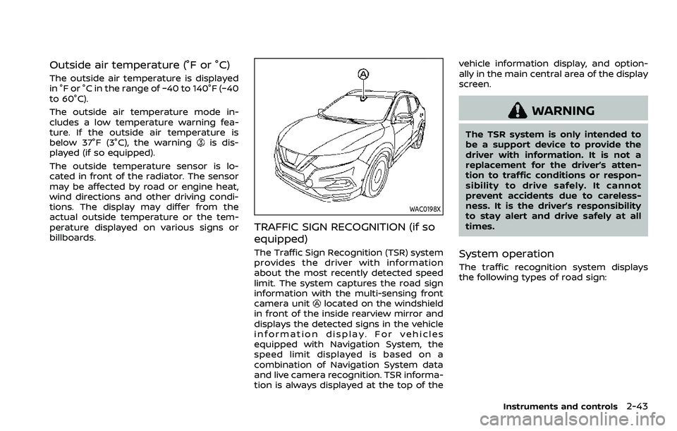
information with the multi-sensing front
camera unit
located on the windshield
in front of the inside rearview mirror and
displays the detected signs in the vehicle
information display. For vehicles
equipped with Navigation System, the
speed limit displayed is based on a
combination of Navigation System data
and live camera recognition. TSR informa-
tion is always displayed at the top of the vehicle information display, and option-
ally in the main central area of the display
screen.
WARNING
The TSR system is only intended to
be a support device to provide the
driver with information. It is not a
replacement for the driver’s atten-
tion to traffic conditions or respon-
sibility to drive safely. It cannot
prevent accidents due to careless-
ness. It is the driver’s responsibility
to stay alert and drive safely at all
times.
System operation
The traffic recognition system displays
the following types of road sign:
Instruments and controls2-43
Page 127 of 516
— When overtaking buses ortrucks with speed stickers.
Turning the TSR system on and off
Turning the TSR system on or off is done
using the "Settings" menu in the vehicle
information display. For details, see “Ve-
hicle information display” (P.2-19).
Perform the following steps to enable or
disable the TSR system:
1. In the "Settings" menu, select the "Driver Assistance" key.
2. Touch "Speed Limit Sign" to turn the system ON/OFF.
System temporarily unavailable
If the vehicle is parked in direct sunlight
under high temperature conditions (over
approximately 40°C (104°F)) and then
started, the TSR system may be deacti-
vated automatically. The “Unavailable:
high cabin temperature” warning mes-
sage will appear in the vehicle informa-
tion display.
Action to take:
When the interior temperature is reduced,
the TSR system will resume operating
automatically.
System Malfunction
If the TSR system malfunctions it will be
turned off automatically and the TSR
"Malfunction" warning message will ap-
pear in the vehicle information display.
Action to take:
If the TSR "Malfunction" warning mes-
sage appears, pull off the road at a safe
location and stop the vehicle. Turn the
engine off and restart the engine. If the
TSR "Malfunction" message continues to
appear, have the system checked by a
NISSAN dealer.
Maintenance
The TSR uses the same multi-sensing
front camera unit that is used by the
Lane Departure Warning (LDW) system,
located in front of the interior rearview
mirror. For maintenance of the camera,
see “System maintenance” (P.5-39).
JVI1587X
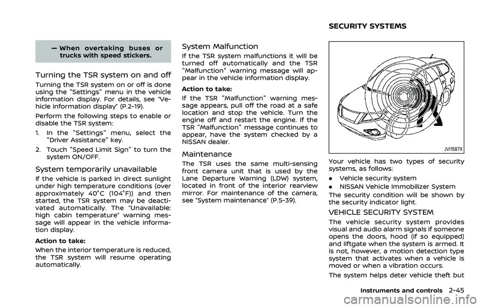
Your vehicle has two types of security
systems, as follows:
.Vehicle security system
. NISSAN Vehicle Immobilizer System
The security condition will be shown by
the security indicator light.
VEHICLE SECURITY SYSTEM
The vehicle security system provides
visual and audio alarm signals if someone
opens the doors, hood (if so equipped)
and liftgate when the system is armed. It
is not, however, a motion detection type
system that activates when a vehicle is
moved or when a vibration occurs.
The system helps deter vehicle theft but
Instruments and controls2-45
SECURITY SYSTEMS
Page 202 of 516
3-32Pre-driving checks and adjustments
SPA2447
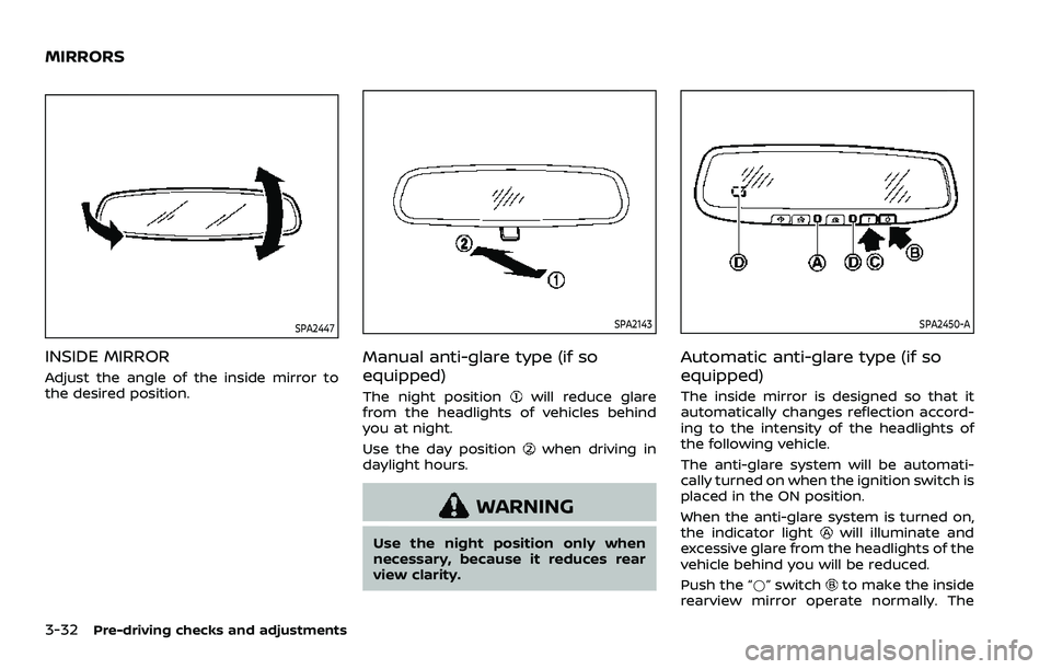
INSIDE MIRROR
Adjust the angle of the inside mirror to
the desired position.
SPA2143
Manual anti-glare type (if so
equipped)
The night positionwill reduce glare
from the headlights of vehicles behind
you at night.
Use the day position
when driving in
daylight hours.
WARNING
Use the night position only when
necessary, because it reduces rear
view clarity.
SPA2450-A
Automatic anti-glare type (if so
equipped)
The inside mirror is designed so that it
automatically changes reflection accord-
ing to the intensity of the headlights of
the following vehicle.
The anti-glare system will be automati-
cally turned on when the ignition switch is
placed in the ON position.
When the anti-glare system is turned on,
the indicator light
will illuminate and
excessive glare from the headlights of the
vehicle behind you will be reduced.
Push the “*” switch
to make the inside
rearview mirror operate normally. The
MIRRORS
Page 203 of 516
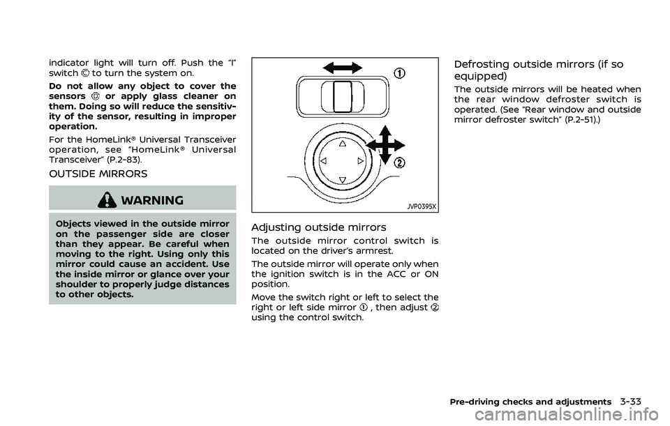
indicator light will turn off. Push the “I”
switchto turn the system on.
Do not allow any object to cover the
sensors
or apply glass cleaner on
them. Doing so will reduce the sensitiv-
ity of the sensor, resulting in improper
operation.
For the HomeLink® Universal Transceiver
operation, see “HomeLink® Universal
Transceiver” (P.2-83).
OUTSIDE MIRRORS
WARNING
Objects viewed in the outside mirror
on the passenger side are closer
than they appear. Be careful when
moving to the right. Using only this
mirror could cause an accident. Use
the inside mirror or glance over your
shoulder to properly judge distances
to other objects.
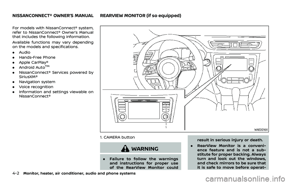
JVP0395X
Adjusting outside mirrors
The outside mirror control switch is
located on the driver’s armrest.
The outside mirror will operate only when
the ignition switch is in the ACC or ON
position.
Move the switch right or left to select the
right or left side mirror
, then adjustusing the control switch.
Defrosting outside mirrors (if so
equipped)
The outside mirrors will be heated when
the rear window defroster switch is
operated. (See “Rear window and outside
mirror defroster switch” (P.2-51).)
Pre-driving checks and adjustments3-33
Page 208 of 516
4-2Monitor, heater, air conditioner, audio and phone systems
For models with NissanConnect® system,
refer to NissanConnect® Owner’s Manual
that includes the following information.
Available functions may vary depending
on the models and specifications.
.Audio
. Hands-Free Phone
. Apple CarPlay®
. Android Auto
TM
.NissanConnect® Services powered by
SiriusXM®
. Navigation system
. Voice recognition
. Information and settings viewable on
NissanConnect®
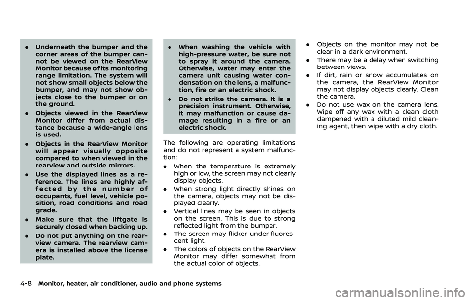
WAE0016X
1. CAMERA button
WARNING
.Failure to follow the warnings
and instructions for proper use
of the RearView Monitor could result in serious injury or death.
. RearView Monitor is a conveni-
ence feature and is not a sub-
stitute for proper backing. Always
turn and look out the windows,
and check mirrors to be sure that
it is safe to move before operat-
NISSANCONNECT® OWNER’S MANUALREARVIEW MONITOR (if so equipped)
Page 214 of 516
4-8Monitor, heater, air conditioner, audio and phone systems
.Underneath the bumper and the
corner areas of the bumper can-
not be viewed on the RearView
Monitor because of its monitoring
range limitation. The system will
not show small objects below the
bumper, and may not show ob-
jects close to the bumper or on
the ground.
. Objects viewed in the RearView
Monitor differ from actual dis-
tance because a wide-angle lens
is used.
. Objects in the RearView Monitor
will appear visually opposite
compared to when viewed in the
rearview and outside mirrors.
. Use the displayed lines as a re-
ference. The lines are highly af-
fected by the number of
occupants, fuel level, vehicle po-
sition, road conditions and road
grade.
. Make sure that the liftgate is
securely closed when backing up.
. Do not put anything on the rear-
view camera. The rearview cam-
era is installed above the license
plate. .
When washing the vehicle with
high-pressure water, be sure not
to spray it around the camera.
Otherwise, water may enter the
camera unit causing water con-
densation on the lens, a malfunc-
tion, fire or an electric shock.
. Do not strike the camera. It is a
precision instrument. Otherwise,
it may malfunction or cause da-
mage resulting in a fire or an
electric shock.
The following are operating limitations
and do not represent a system malfunc-
tion:
. When the temperature is extremely
high or low, the screen may not clearly
display objects.
. When strong light directly shines on
the camera, objects may not be dis-
played clearly.
. Vertical lines may be seen in objects
on the screen. This is due to strong
reflected light from the bumper.
. The screen may flicker under fluores-
cent light.
. The colors of objects on the RearView
Monitor may differ somewhat from
the actual color of objects. .
Objects on the monitor may not be
clear in a dark environment.
. There may be a delay when switching
between views.
. If dirt, rain or snow accumulates on
the camera, the RearView Monitor
may not display objects clearly. Clean
the camera.
. Do not use wax on the camera lens.
Wipe off any wax with a clean cloth
dampened with a diluted mild clean-
ing agent, then wipe with a dry cloth.
Page 217 of 516

.Front view
The view to the front of the vehicle.
. Rear view
The view to the rear of the vehicle.
. Bird’s-eye view
The views to the vehicle from above.
. Front-side view
The view around and ahead of the
front passenger’s side wheel.
WAE0211X
To display the multiple views, the Intelli-
gent Around View® Monitor system uses
cameras
located in the front grille, on
the vehicle’s outside mirrors and one just
above the vehicle’s license plate.
INTELLIGENT AROUND VIEW®
MONITOR SYSTEM OPERATION
When the ignition switch is placed in the
ON position, push the CAMERA button on
the instrument panel or move the shift
lever to the R (Reverse) position to
operate the Intelligent Around View®
Monitor.
The screen displayed on the Intelligent
Around View® Monitor will automatically
return to the previous screen 3 minutes after the CAMERA button has been
pushed with the shift lever in a position
other than the R (Reverse) position.
Available views
WARNING
.
The distance guide lines and the
vehicle width guide lines should
be used as a reference only when
the vehicle is on a paved, level
surface. The apparent distance
viewed on the monitor may be
different than the actual distance
between the vehicle and dis-
played objects.
. Use the displayed lines and the
bird’s-eye view as a reference.
The lines and the bird’s-eye view
are greatly affected by the num-
ber of occupants, fuel level, vehi-
cle position, road condition and
road grade.
. If the tires are replaced with
different sized tires, the predic-
tive course lines and the bird’s-
eye view may be displayed incor-
rectly.
. When driving the vehicle up a hill,
objects viewed in the monitor are
Monitor, heater, air conditioner, audio and phone systems4-11
Page 218 of 516
4-12Monitor, heater, air conditioner, audio and phone systems
farther than they appear. When
driving the vehicle down a hill,
objects viewed in the monitor are
closer than they appear.
. Objects in the rear view will ap-
pear visually opposite compared
to when viewed in the rearview
and outside mirrors.
. Use the mirrors or actually look to
properly judge distances to other
objects.
. On a snow-covered or slippery
road, there may be a difference
between the predictive course
line and the actual course line.
. The vehicle width and predictive
course lines are wider than the
actual width and course.
. The displayed lines on the rear
view will appear slightly off to the
right because the rear view cam-
era is not installed in the rear
center of the vehicle.
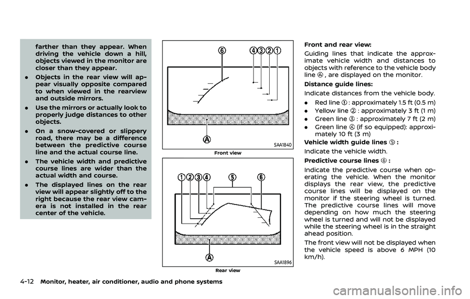
SAA1840
Front view
SAA1896Rear view
Front and rear view:
Guiding lines that indicate the approx-
imate vehicle width and distances to
objects with reference to the vehicle body
line
, are displayed on the monitor.
Distance guide lines:
Indicate distances from the vehicle body.
. Red line
: approximately 1.5 ft (0.5 m)
. Yellow line
: approximately 3 ft (1 m)
. Green line
: approximately 7 ft (2 m)
. Green line
(if so equipped): approxi-
mately 10 ft (3 m)
Vehicle width guide lines
:
Indicate the vehicle width.
Predictive course lines
:
Indicate the predictive course when op-
erating the vehicle. When the monitor
displays the rear view, the predictive
course lines will be displayed on the
monitor if the steering wheel is turned.
The predictive course lines will move
depending on how much the steering
wheel is turned and will not be displayed
while the steering wheel is in the straight
ahead position.
The front view will not be displayed when
the vehicle speed is above 6 MPH (10
km/h).
Page 224 of 516
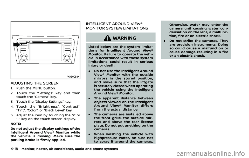
4-18Monitor, heater, air conditioner, audio and phone systems
WAE0058X
ADJUSTING THE SCREEN
1. Push the MENU button.
2. Touch the “Settings” key and thentouch the “Camera” key.
3. Touch the “Display Settings” key.
4. Touch the “Brightness”, “Contrast”, “Tint”, “Color”, or “Black Level” key.
5. Adjust the item by touching the “+” or “–” key on the touch screen display.
NOTE:
Do not adjust the display settings of the
Intelligent Around View® Monitor while
the vehicle is moving. Make sure the
parking brake is firmly applied.
INTELLIGENT AROUND VIEW®
MONITOR SYSTEM LIMITATIONS
WARNING
Listed below are the system limita-
tions for Intelligent Around View®
Monitor. Failure to operate the vehi-
cle in accordance with these system
limitations could result in serious
injury or death.
. Do not use the Intelligent Around
View® Monitor with the outside
mirrors in the stored position,
and make sure that the liftgate
is securely closed when operating
the vehicle using the Intelligent
Around View® Monitor.
. The apparent distance between
objects viewed on the Intelligent
Around View® Monitor differs
from the actual distance.
. The cameras are installed above
the front grille, the outside mir-
rors and above the rear license
plate. Do not put anything on the
cameras.
. When washing the vehicle with
highpressure water, be sure not
to spray it around the cameras. Otherwise, water may enter the
camera unit causing water con-
densation on the lens, a malfunc-
tion, fire or an electric shock.
. Do not strike the cameras. They
are precision instruments. Doing
so could cause a malfunction or
cause damage resulting in a fire
or an electric shock.