traction control NISSAN ROGUE SPORT 2021 Owners Manual
[x] Cancel search | Manufacturer: NISSAN, Model Year: 2021, Model line: ROGUE SPORT, Model: NISSAN ROGUE SPORT 2021Pages: 516, PDF Size: 2.43 MB
Page 99 of 516
commended you visit a NISSAN dealer
for this service. You do not need to
have your vehicle towed to the dealer.
CAUTION
Continued vehicle operation without
having the emission control system
and/or CVT system checked and
repaired as necessary could lead to
poor driveability, reduced fuel econ-
omy, and possible damage to the
emission control system.
Rear Automatic Braking (RAB)
system warning light
This light comes on when the ignition
switch is placed in the ON position. It
turns off after the engine is started.
This light illuminates when the RAB sys-
tem is turned off in the vehicle informa-
tion display.
If the light illuminates when the RAB
system is on, it may indicate that the
system is unavailable. For additional in-
formation, see “Rear Automatic Braking
(RAB)” (P.5-116).
Vehicle Dynamic Control (VDC)
off indicator light
When the ignition switch is in the ON
position, the Vehicle Dynamic Control
(VDC) off indicator light illuminates and
then turns off.
The light comes on when the Vehicle
Dynamic Control (VDC) off switch is
pushed to OFF. This indicates that the
VDC system and traction control system
are not operating.
Vehicle Dynamic Control (VDC)
warning light
When the ignition switch is in the ON
position, the Vehicle Dynamic Control
(VDC) warning light illuminates and then
turns off.
The light will blink when the Vehicle
Dynamic Control (VDC) system or the
traction control system is operating, thus
alerting the driver that the vehicle is
nearing its traction limits. The road sur-
face may be slippery.
If the VDC warning light illuminates while
the VDC system is on, this light alerts the
driver to the fact that the VDC system’s
fail-safe mode is operating, for example
the VDC system may not be functioning
properly. Have the system checked. It is recommended you visit a NISSAN dealer
for this service. If a malfunction occurs in
the system, the VDC system function will
be canceled but the vehicle is still drive-
able. For additional information, see “Ve-
hicle Dynamic Control (VDC) system” (P.5-
131) of this manual.
WARNING/INDICATOR LIGHTS
(other)
See “Vehicle information display” (P.2-19).
Automatic brake hold indica-
tor light (green) (if so equipped)
The automatic brake hold indicator light
(green) illuminates while the automatic
brake hold system is operating. (See
“Automatic brake hold” (P.5-29).)
Automatic brake hold indica-
tor light (white) (if so equipped)
The automatic brake hold indicator light
(white) illuminates when the automatic
brake hold system is on standby. (See
“Automatic brake hold” (P.5-29).)
Instruments and controls2-17
Page 254 of 516

5-12Starting and driving
similar equipment even if the
other two wheels are raised off
the ground. Make sure you inform
test facility personnel that your
vehicle is equipped with AWD
before it is placed on a dynam-
ometer. Using the wrong test
equipment may result in drive-
train damage or unexpected ve-
hicle movement which could
result in serious vehicle damage
or personal injury.
. When a wheel is off the ground
due to an unlevel surface, do not
spin the wheel excessively (AWD
model).
. Accelerating quickly, sharp steer-
ing maneuvers or sudden braking
may cause loss of control.
. If at all possible, avoid sharp
turning maneuvers, particularly
at high speeds. Your vehicle has
a higher center of gravity than a
conventional passenger car. The
vehicle is not designed for cor-
nering at the same speeds as
conventional passenger cars.
Failure to operate this vehicle
correctly could result in loss of
control and/or a rollover acci-
dent. .
Always use tires of the same type,
size, brand, construction (bias,
bias-belted or radial), and tread
pattern on all four wheels. Install
traction devices on the front
wheels when driving on slippery
roads and drive carefully.
. Be sure to check the brakes im-
mediately after driving in mud or
water. See “Brake system” (P.5-
129) for wet brakes.
. Avoid parking your vehicle on
steep hills. If you get out of the
vehicle and it rolls forward, back-
ward or sideways, you could be
injured.
. Whenever you drive off-road
through sand, mud or water as
deep as the wheel hub, more
frequent maintenance may be
required. See the maintenance
schedule shown in the “9. Main-
tenance and schedules” section.
. Spinning the front wheels on
slippery surfaces may cause the
AWD warning message to display
and the AWD system to automa-
tically switch from the AWD mode
to the 2WD mode. This could
reduce traction. (AWD models)WARNING
Never remove the key or place the
ignition switch in the LOCK position
while driving. The steering wheel will
lock and could cause the driver to
lose control of the vehicle. This could
result in serious vehicle damage or
personal injury.
IGNITION SWITCH (models without
Intelligent Key system)
Page 313 of 516
WAF0052X
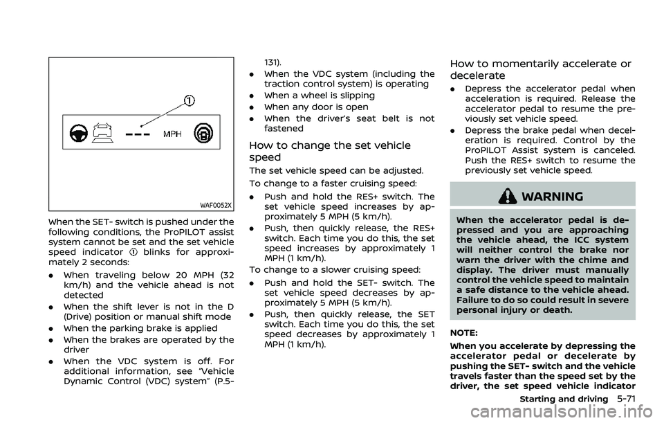
When the SET- switch is pushed under the
following conditions, the ProPILOT assist
system cannot be set and the set vehicle
speed indicator
blinks for approxi-
mately 2 seconds:
. When traveling below 20 MPH (32
km/h) and the vehicle ahead is not
detected
. When the shift lever is not in the D
(Drive) position or manual shift mode
. When the parking brake is applied
. When the brakes are operated by the
driver
. When the VDC system is off. For
additional information, see “Vehicle
Dynamic Control (VDC) system” (P.5- 131).
. When the VDC system (including the
traction control system) is operating
. When a wheel is slipping
. When any door is open
. When the driver’s seat belt is not
fastened
How to change the set vehicle
speed
The set vehicle speed can be adjusted.
To change to a faster cruising speed:
.Push and hold the RES+ switch. The
set vehicle speed increases by ap-
proximately 5 MPH (5 km/h).
. Push, then quickly release, the RES+
switch. Each time you do this, the set
speed increases by approximately 1
MPH (1 km/h).
To change to a slower cruising speed:
. Push and hold the SET- switch. The
set vehicle speed decreases by ap-
proximately 5 MPH (5 km/h).
. Push, then quickly release, the SET
switch. Each time you do this, the set
speed decreases by approximately 1
MPH (1 km/h).
How to momentarily accelerate or
decelerate
. Depress the accelerator pedal when
acceleration is required. Release the
accelerator pedal to resume the pre-
viously set vehicle speed.
. Depress the brake pedal when decel-
eration is required. Control by the
ProPILOT Assist system is canceled.
Push the RES+ switch to resume the
previously set vehicle speed.
WARNING
When the accelerator pedal is de-
pressed and you are approaching
the vehicle ahead, the ICC system
will neither control the brake nor
warn the driver with the chime and
display. The driver must manually
control the vehicle speed to maintain
a safe distance to the vehicle ahead.
Failure to do so could result in severe
personal injury or death.
NOTE:
When you accelerate by depressing the
accelerator pedal or decelerate by
pushing the SET- switch and the vehicle
travels faster than the speed set by the
driver, the set speed vehicle indicator
Starting and driving5-71
Page 325 of 516
.Any door is open.
. The driver’s seat belt is not fastened.
. The vehicle ahead is not detected and
your vehicle is traveling below the
speed of 15 MPH (24 km/h).
. Your vehicle has been stopped by the
ICC system for approximately 3 min-
utes or longer.
. The shift lever is not in the D (Drive)
position or manual shift mode.
. The electronic parking brake is ap-
plied.
. The VDC system is turned off.
. The AEB applies harder braking
. VDC (including the traction control
system) operates.
. A wheel slips.
. When distance measurement be-
comes impaired due to adhesion of
dirt or obstruction to the sensor.
. When the radar signal is temporarily
interrupted.
Action to take:
When the conditions listed above are no
longer present, turn the system off using
the ProPILOT Assist switch. Turn the
ProPILOT Assist system back on to use
the system. NOTE:
When the ICC system is canceled under
the following conditions at a standstill,
the electronic parking brake is automa-
tically activated:
.
Any door is open.
. The driver’s seat belt is not fastened.
. Your vehicle has been stopped by
the ICC system for approximately 3
minutes or longer.
. The shift lever is not in the D (Drive)
position or manual shift mode.
. The VDC system is turned off.
. When distance measurement be-
comes impaired due to adhesion of
dirt or obstruction to the sensor.
. When the radar signal is temporarily
interrupted.
Condition B:
When the radar sensor of the front
bumper is covered with dirt or is ob-
structed, the ICC system will automati-
cally be canceled.
The chime will sound and the “Forward
Driving Aids Temporarily Disabled Front
Sensor Blocked” or “Unavailable: Front
Radar Obstruction” warning message will
appear in the vehicle information display. Action to take:
If the warning message appears, stop the
vehicle in a safe place, place the shift lever
in the P (Park) position, and turn the
engine off. When the radar signal is
temporarily interrupted, clean the sensor
area of the front bumper and restart the
engine. If the “Forward Driving Aids Tem-
porarily Disabled Front Sensor Blocked” or
“Unavailable: Front Radar Obstruction”
warning message continues to be dis-
played, have the system checked. It is
recommended that you visit a NISSAN
dealer for this service.
Condition C:
When driving on roads with limited road
structures or buildings (for example, long
bridges, deserts, snow fields, driving next
to long walls), the system may illuminate
the system warning light and display the
“Forward Driving Aids Temporarily Dis-
abled Front Sensor Blocked” or “Unavail-
able: Front Radar Obstruction” warning
message.
Action to take:
When the above driving conditions no
longer exist, turn the system back on.
Starting and driving5-83
Page 336 of 516
5-94Starting and driving
3. Push, then quickly release the SET—switch. Each time you do this, the set
speed will decrease by about 1 MPH
(1.6 km/h).
To resume the preset speed, push and
release the RES+ switch. The vehicle will
resume the last set cruising speed when
the vehicle speed is over 25 MPH (40
km/h).
WARNING
Failure to follow the warnings and
instructions for proper use of the
Intelligent Driver Alertness system
could result in serious injury or
death.
. The I-DA system is only a warning
to inform the driver of a potential
lack of driver attention or drowsi-
ness. It will not steer the vehicle
or prevent loss of control.
. The I-DA system does not detect
and provide an alert of the dri-
ver’s lack of attention or fatigue
in every situation.
. It is the driver’s responsibility to:
— stay alert,
— drive safely,
— keep the vehicle in the travel-
ing lane,
— be in control of the vehicle at all times,
— avoid driving when tired,
— avoid distractions (texting, etc). The I-DA system helps alert the driver if
the system detects a lack of attention or
driving fatigue.
The system monitors driving style and
steering behavior over a period of time,
and it detects changes from the normal
pattern. If the system detects that driver
attention is decreasing over a period of
time, the system uses audible and visual
warnings to suggest that the driver take a
break.
INTELLIGENT DRIVER ALERTNESS
(I-DA) (if so equipped)
Page 373 of 516
tion. If the computer senses a malfunc-
tion, it switches the ABS off and illumi-
nates the ABS warning light on the
instrument panel. The brake system then
operates normally, but without anti-lock
assistance.
If the ABS warning light illuminates during
the self-test or while driving, have the
vehicle checked. It is recommended you
visit a NISSAN dealer for this service.
Normal operation
The ABS operates at speeds above 3 to 6
MPH (5 to 10 km/h). The speed varies
according to road conditions.
When the ABS senses that one or more
wheels are close to locking up, the
actuator rapidly applies and releases
hydraulic pressure. This action is similar
to pumping the brakes very quickly. You
may feel a pulsation in the brake pedal
and hear a noise from under the hood or
feel a vibration from the actuator when it
is operating. This is normal and indicates
that the ABS is operating properly. How-
ever, the pulsation may indicate that road
conditions are hazardous and extra care
is required while driving.The Vehicle Dynamic Control (VDC) sys-
tem uses various sensors to monitor
driver inputs and vehicle motion. Under
certain driving conditions, the VDC sys-
tem helps to perform the following func-
tions.
.
Controls brake pressure to reduce
wheel slip on one slipping drive wheel
so power is transferred to a non
slipping drive wheel on the same axle.
. Controls brake pressure and engine
output to reduce drive wheel slip
based on vehicle speed (traction con-
trol function).
. Controls brake pressure at individual
wheels and engine output to help the
driver maintain control of the vehicle
in the following conditions:
— understeer (vehicle tends to not
follow the steered path despite
increased steering input)
— oversteer (vehicle tends to spin due to certain road or driving condi-
tions).
The VDC system can help the driver to
maintain control of the vehicle, but it
cannot prevent loss of vehicle control in
all driving situations.
When the VDC system operates, the VDC
warning light
in the instrument panel
flashes so note the following: .
The road may be slippery or the
system may determine some action
is required to help keep the vehicle on
the steered path.
. You may feel a pulsation in the brake
pedal and hear a noise or vibration
from under the hood. This is normal
and indicates that the VDC system is
working properly.
. Adjust your speed and driving to the
road conditions.
If a malfunction occurs in the system, the
VDC warning light
illuminates in the
instrument panel. The VDC system auto-
matically turns off.
The VDC OFF switch is used to turn off the
VDC system. The VDC off indicator
illuminates to indicate the VDC system is
off. When the VDC switch is used to turn
off the system, the VDC system still
operates to prevent one drive wheel from
slipping by transferring power to a non
slipping drive wheel. The VDC warning
light
flashes if this occurs. All other
VDC functions are off, and the VDC
warning light
will not flash. The VDC
system is automatically reset to on when
the ignition switch is placed in the off
position then back to the on position.
See “Vehicle Dynamic Control (VDC) warn-
ing light” (P.2-17) and “Vehicle Dynamic
Control (VDC) off indicator light” (P.2-17).
Starting and driving5-131
VEHICLE DYNAMIC CONTROL (VDC) SYSTEM
Page 384 of 516

5-142Starting and driving
All-Wheel Drive (AWD) model
If you install snow tires, they must also be
the same size, brand, construction and
tread pattern on all four wheels.
SPECIAL WINTER EQUIPMENT
It is recommended that the following
items be carried in the vehicle during
winter:
.A scraper and stiff-bristled brush to
remove ice and snow from the win-
dows and wiper blades.
. A sturdy, flat board to be placed under
the jack to give it firm support.
. A shovel to dig the vehicle out of
snow-drifts.
. Extra window washer fluid to refill the
reservoir tank.
DRIVING ON SNOW OR ICE
WARNING
.Wet ice (32°F, 0°C and freezing
rain), very cold snow or ice can be
slick and very hard to drive on.
The vehicle will have much less
traction or “grip” under these
conditions. Try to avoid driving
on wet ice until the road is salted
or sanded. .
Whatever the condition, drive
with caution. Accelerate and slow
down with care. If accelerating or
downshifting too fast, the drive
wheels will lose even more trac-
tion.
. Allow more stopping distance
under these conditions. Braking
should be started sooner than on
dry pavement.
. Allow greater following distances
on slippery roads.
. Watch for slippery spots (glare
ice). These may appear on an
otherwise clear road in shaded
areas. If a patch of ice is seen
ahead, brake before reaching it.
Try not to brake while on the ice,
and avoid any sudden steering
maneuvers.
. Do not use cruise control on
slippery roads.
. Snow can trap dangerous ex-
haust gases under your vehicle.
Keep snow clear of the exhaust
pipe and from around your vehi-
cle.
Page 450 of 516
8-36Do-it-yourself
.For additional information re-
garding tires, refer to “Important
Tire Safety Information” (US) or
“Tire Safety Information” (Cana-
da) in the Warranty Information
Booklet.
. Always use tires of the same type,
size, brand, construction and
tread pattern on all four wheels.
Failure to do so may result in a
circumference difference be-
tween tires on the front and rear
axles which can cause the Vehicle
Dynamic Control (VDC) system to
malfunction resulting in personal
injury or death, excessive tire
wear and may damage the trans-
mission, transfer case and differ-
ential gears.
All season tires
NISSAN specifies all season tires on some
models to provide good performance all
year, including snowy and icy road con-
ditions. All Season tires are identified by
ALL SEASON and/or M&S (Mud and Snow)
on the tire sidewall. Snow tires have
better snow traction than All Season tires
and may be more appropriate in some
areas.
Summer tires
NISSAN specifies summer tires on some
models to provide superior performance
on dry roads. Summer tire performance is
substantially reduced in snow and ice.
Summer tires do not have the tire trac-
tion rating M&S on the tire sidewall.
If you plan to operate your vehicle in
snowy or icy conditions, NISSAN recom-
mends the use of SNOW tires or ALL
SEASON tires on all four wheels.
Snow tires
If snow tires are needed, it is necessary to
select tires equivalent in size and load
rating to the original equipment tires. If
you do not, it can adversely affect the
safety and handling of your vehicle.
Generally, snow tires will have lower
speed ratings than factory equipped tires
and may not match the potential max-
imum vehicle speed. Never exceed the
maximum speed rating of the tire.
If you install snow tires, they must be the
same size, brand, construction and tread
pattern on all four wheels.
For additional traction on icy roads,
studded tires may be used. However,
some U.S. states and Canadian provinces
prohibit their use. Check local, state and
provincial laws before installing studded tires. Skid and traction capabilities of
studded snow tires, on wet or dry sur-
faces, may be poorer than that of non-
studded snow tires.
TIRE CHAINS
Use of tire chains may be prohibited
according to location. Check the local
laws before installing tire chains. When
installing tire chains, make sure they are
the proper size for the tires on your
vehicle and are installed according to
the chain manufacturer’s suggestions.
Use only SAE Class S chains.
Class “S”
chains are used on vehicles with re-
stricted tire to vehicle clearance. Vehicles
that can use Class “S” chains are designed
to meet the SAE standard minimum
clearances between the tire and the
closest vehicle suspension or body com-
ponent required to accommodate the
use of a winter traction device (tire chains
or cables). The minimum clearances are
determined using the factory equipped
tire size. Other types may damage your
vehicle. Use chain tensioners when re-
commended by the tire chain manufac-
turer to ensure a tight fit. Loose end links
of the tire chain must be secured or
removed to prevent the possibility of
whipping action damage to the fenders
or underbody. If possible, avoid fully load-
ing your vehicle when using tire chains. In
Page 479 of 516
10 Technical and consumer information
Capacities and
recommended fluids/lubricants .................................... 10-2Fuel information .................................................................. 10-3
Engine oil and oil filter recommendation ........ 10-5
Air conditioning system refrigerant and
oil recommendations ....................................................... 10-6
Specifications ........................................................................\
........ 10-7 Engine ........................................................................\
.................. 10-7
Wheels and tires .................................................................. 10-7
Dimensions and weights .............................................. 10-8
When traveling or registering in
another country ........................................................................\
. 10-8
Vehicle identification .............................................................. 10-8 Vehicle Identification Number (VIN) plate ....... 10-8
Vehicle identification number
(chassis number) ................................................................. 10-9
Engine serial number ....................................................... 10-9
F.M.V.S.S./C.M.V.S.S. certification label ................. 10-9
Emission control information label .................. 10-10
Tire and Loading Information label ................. 10-10
Air conditioner specification label ..................... 10-10
Installing front license plate ......................................... 10-12
Vehicle loading information .......................................... 10-12
Terms ........................................................................\
................ 10-12 Vehicle load capacity ................................................ 10-13
Securing the load ......................................................... 10-14
Loading tips ...................................................................... 10-14
Measurement of weights ....................................... 10-15
Towing a trailer ...................................................................... 10-15
Flat towing ........................................................................\
......... 10-16
Flat towing for All–Wheel Drive vehicle
(if so equipped) ............................................................... 10-16
Flat towing for Front-Wheel Drive vehicle
(if so equipped) ............................................................... 10-16
Uniform tire quality grading ........................................ 10-17 Treadwear ........................................................................\
.. 10-17
Traction AA, A, B and C ........................................... 10-17
Temperature A, B and C ......................................... 10-17
Emission control system warranty ......................... 10-18
Reporting safety defects ................................................ 10-18
Readiness for Inspection/Maintenance
(I/M) test ........................................................................\
............... 10-19
Event Data Recorders (EDR) ......................................... 10-20 Additional data recording (on vehicles
equipped with optional
ProPILOT assist) ............................................................. 10-20
Owner’s manual/service manual
order information ................................................................. 10-21
Page 495 of 516
DOT (Department Of Transportation)
Quality Grades: All passenger car tires
must conform to federal safety require-
ments in addition to these grades.
Quality grades can be found where ap-
plicable on the tire sidewall between
tread shoulder and maximum section
width. For example:
Treadwear 200 Traction AA Tempera-
ture A
TREADWEAR
The treadwear grade is a comparative
rating based on the wear rate of the tire
when tested under controlled conditions
on a specified government test course.
For example, a tire graded 150 would
wear one and one-half
(1 1/2) times as well on the government
course as a tire graded 100. The relative
performance of tires depends upon ac-
tual conditions of their use, however, and
may depart significantly from the norm
due to variations in driving habits, service
practices and differences in road charac-
teristics and climate.
TRACTION AA, A, B AND C
The traction grades, from highest to low-
est, are AA, A, B and C. Those grades
represent the tire’s ability to stop on wet
pavement as measured under controlled
conditions on specified government test
surfaces of asphalt and concrete. A tire
marked C may have poor traction perfor-
mance.
WARNING
The traction grade assigned to this
tire is based on straight-ahead brak-
ing traction tests, and does not
include acceleration, cornering, hy-
droplaning, or peak traction charac-
teristics.
TEMPERATURE A, B AND C
The temperature grades A (the highest),
B, and C, representing the tire’s resistance
to the generation of heat and its ability to
dissipate heat when tested under con-
trolled conditions on a specified indoor
laboratory test wheel. Sustained high
temperature can cause the material of
the tire to degenerate and reduce tire life,
and excessive temperature can lead to
sudden tire failure. The grade C corre-
sponds to a level of performance whichall passenger car tires must meet under
the Federal Motor Vehicle Safety Stan-
dard No. 109. Grades B and A represent
higher levels of performance on the
laboratory test wheel than the minimum
required by law.
WARNING
The temperature grade for this tire is
established for a tire that is properly
inflated and not overloaded. Exces-
sive speed, under-inflation, or exces-
sive loading, either separately or in
combination, can cause heat build-
up and possible tire failure.
Technical and consumer information10-17
UNIFORM TIRE QUALITY GRADING