mirror NISSAN ROGUE SPORT 2022 Owner's Manual
[x] Cancel search | Manufacturer: NISSAN, Model Year: 2022, Model line: ROGUE SPORT, Model: NISSAN ROGUE SPORT 2022Pages: 508, PDF Size: 2.43 MB
Page 228 of 508
4-22Monitor, heater, air conditioner, audio and phone systems
always use the outside mirror
and rearview mirror and turn
and check the surroundings to
ensure it is safe to maneuver.
. The system is deactivated at
speeds above 5 MPH (8 km/h). It
is reactivated at lower speeds.
. The MOD system is not designed
to detect the surrounding sta-
tionary objects.
The MOD system can inform the driver of
moving objects near the vehicle when
driving out of garages, maneuvering in
parking lots and in other such instances.
The MOD system detects moving objects
by using image processing technology on
the image shown in the display.
MOD SYSTEM OPERATION
The MOD system will turn on automati-
cally under the following conditions:
. When the shift lever is in the R
(Reverse) position.
. When the CAMERA button is pushed
to activate the Intelligent Around
View® Monitor system on the display.
. When vehicle speed decreases below
approximately 5 MPH (8 km/h).
The MOD system operates in the follow-
ing conditions when the camera view is displayed:
.
When the shift lever is in the P (Park) or
N (Neutral) position and the vehicle is
stopped, the MOD system detects the
moving objects in the bird’s-eye view.
The MOD system will not operate if
either door is opened. If outside mir-
rors are folded, MOD may not operate
properly.
. When the shift lever is in the D (Drive)
position, and the vehicle speed is
below approximately 5 MPH (8 km/h),
the MOD system detects moving ob-
jects in the front view.
. When the shift lever is in the R
(Reverse) position and the vehicle
speed is below approximately 5 MPH
(8 km/h), the MOD system detects
moving objects in the rear view. The
MOD system will not operate if the
liftgate is open.
The MOD system does not detect moving
objects in the front-side view. The MOD
icon is not displayed on the screen when
in this view.
When the MOD system detects a moving
object near the vehicle, the yellow frame
will be displayed on the view where the
object is detected and a chime will sound
once. While the MOD system continues to
detect moving objects, the yellow frame
continues to be displayed. NOTE:
While the RCTA chime (if so equipped) is
beeping, the MOD system does not
chime.
Page 230 of 508
4-24Monitor, heater, air conditioner, audio and phone systems
may not be heard.
. The MOD system performance
will be limited according to en-
vironmental conditions and sur-
rounding objects such as:
— When there is low contrast
between background and the
moving objects.
— When there is blinking source of light.
— When strong light such as another vehicle’s headlight or
sunlight is present.
— When camera orientation is not in its usual position, such
as when the outside mirror is
folded.
— When there is dirt, water drops or snow on the camera lens.
— When the position of the mov- ing objects in the display is
not changed.
. The MOD system might detect
flowing water droplets on the
camera lens, white smoke from
the muffler, moving shadows, etc.
. The MOD system may not func-
tion properly depending on the
speed, direction, distance or shape of the moving objects.
. If your vehicle sustains damage
to the parts where the camera is
installed, leaving it misaligned or
bent, the sensing zone may be
altered and the MOD system may
not detect objects properly.
. When the temperature is extre-
mely high or low, the screen may
not display objects clearly. This is
not a malfunction.
NOTE:
The blue MOD icon will change to
orange if one of the following has
occurred.
. When the system is malfunctioning.
. When the component temperature
reaches a high level (icon will blink).
. When the rear view camera has
detected a blockage (icon will blink).
If the icon light continues to illuminate
orange, have the MOD system checked.
It is recommended that you visit a
NISSAN dealer for this service.
WAE0211X
SYSTEM MAINTENANCE
CAUTION
. Do not use alcohol, benzine or
thinner to clean the camera. This
will cause discoloration.
. Do not damage the camera as the
monitor screen may be adversely
affected.
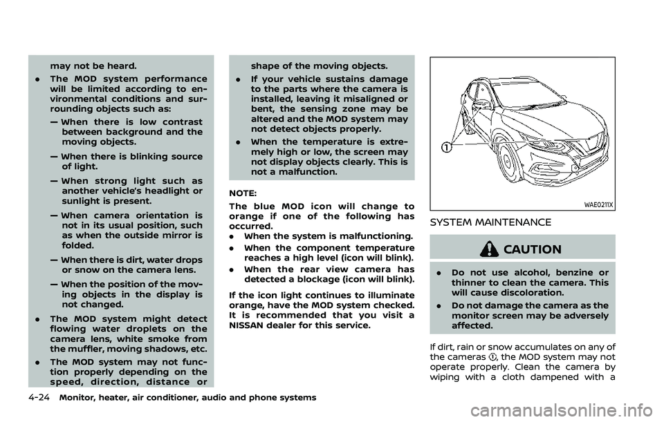
If dirt, rain or snow accumulates on any of
the cameras
, the MOD system may not
operate properly. Clean the camera by
wiping with a cloth dampened with a
Page 233 of 508
JVH0664X
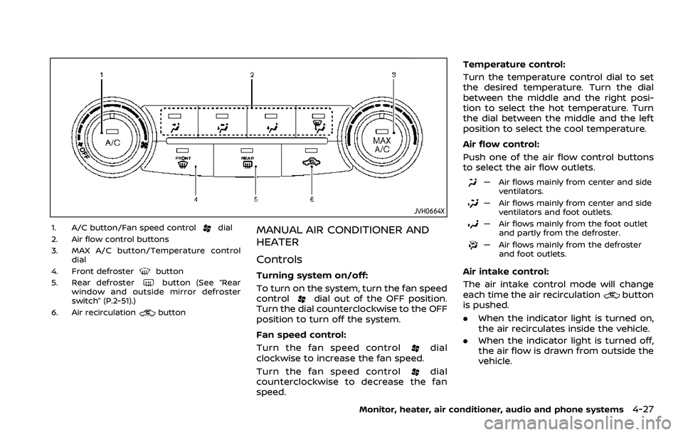
1. A/C button/Fan speed controldial
2. Air flow control buttons
3. MAX A/C button/Temperature control dial
4. Front defroster
button
5. Rear defrosterbutton (See “Rear
window and outside mirror defroster
switch” (P.2-51).)
6. Air recirculation
button
MANUAL AIR CONDITIONER AND
HEATER
Controls
Turning system on/off:
To turn on the system, turn the fan speed
control
dial out of the OFF position.
Turn the dial counterclockwise to the OFF
position to turn off the system.
Fan speed control:
Turn the fan speed control
dial
clockwise to increase the fan speed.
Turn the fan speed control
dial
counterclockwise to decrease the fan
speed. Temperature control:
Turn the temperature control dial to set
the desired temperature. Turn the dial
between the middle and the right posi-
tion to select the hot temperature. Turn
the dial between the middle and the left
position to select the cool temperature.
Air flow control:
Push one of the air flow control buttons
to select the air flow outlets.
— Air flows mainly from center and side
ventilators.
— Air flows mainly from center and sideventilators and foot outlets.
— Air flows mainly from the foot outletand partly from the defroster.
— Air flows mainly from the defrosterand foot outlets.
Air intake control:
The air intake control mode will change
each time the air recirculation
button
is pushed.
. When the indicator light is turned on,
the air recirculates inside the vehicle.
. When the indicator light is turned off,
the air flow is drawn from outside the
vehicle.
Monitor, heater, air conditioner, audio and phone systems4-27
Page 236 of 508
4-30Monitor, heater, air conditioner, audio and phone systems
more than 36°F (2°C). This dehumidifies
the air which helps defog the windshield.
The air recirculation mode automatically
turns off, allowing outside air to be drawn
into the passenger compartment to
further improve the defogging perfor-
mance.
The air conditioner is always on in front
defroster or
mode, regardless of
whether the indicator light is on or off.
NOTE:
. The air conditioner system should
be operated for approximately 10
minutes at least once a month. This
helps prevent damage to the air
conditioner system due to the lack
of lubrication.
. A visible mist may be seen coming
from the ventilators in hot, humid
conditions as the air is cooled ra-
pidly. This does not indicate a mal-
function.
. If the engine coolant temperature
becomes too high, the air recircula-
tion mode will be activated and the
indicator light will come on automa-
tically.
. If the engine coolant temperature
gauge indicates engine coolant tem-
perature over the normal range, turn
the air conditioner off. (See “If your
vehicle overheats” (P.6-16).)
JVH0665X
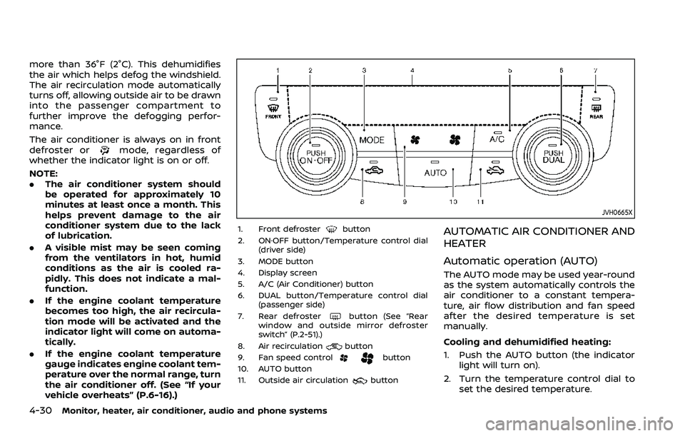
1. Front defrosterbutton
2. ON·OFF button/Temperature control dial (driver side)
3. MODE button
4. Display screen
5. A/C (Air Conditioner) button
6. DUAL button/Temperature control dial (passenger side)
7. Rear defroster
button (See “Rear
window and outside mirror defroster
switch” (P.2-51).)
8. Air recirculation
button
9. Fan speed controlbutton
10. AUTO button
11. Outside air circulation
button
AUTOMATIC AIR CONDITIONER AND
HEATER
Automatic operation (AUTO)
The AUTO mode may be used year-round
as the system automatically controls the
air conditioner to a constant tempera-
ture, air flow distribution and fan speed
after the desired temperature is set
manually.
Cooling and dehumidified heating:
1. Push the AUTO button (the indicator light will turn on).
2. Turn the temperature control dial to set the desired temperature.
Page 257 of 508
JVS0404X
INTELLIGENT KEY BATTERY DIS-
CHARGE
If the battery of the Intelligent Key is
discharged, or environmental conditions
interfere with the Intelligent Key opera-
tion, start the engine according to the
following procedure:
1. Move the shift lever to the P (Park)position (for CVT models) or the shift
lever to the N (Neutral) position (for MT
models).
2. Firmly apply the foot brake.
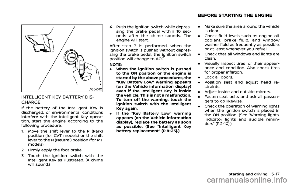
3. Touch the ignition switch with the Intelligent Key as illustrated. (A chime
will sound.) 4. Push the ignition switch while depres-
sing the brake pedal within 10 sec-
onds after the chime sounds. The
engine will start.
After step 3 is performed, when the
ignition switch is pushed without depres-
sing the brake pedal, the ignition switch
position will change to ACC.
NOTE:
. When the ignition switch is pushed
to the ON position or the engine is
started by the above procedures, the
“Key Battery Low” warning appears
(on the Vehicle information display)
even if the Intelligent Key is inside
the vehicle. This is not a malfunction.
To turn off the warning, touch the
ignition switch with the Intelligent
Key again.
. If the “Key Battery Low” warning
appears (on the Vehicle information
display), replace the battery as soon
as possible. (See “Intelligent Key
battery replacement” (P.8-23).)
.Make sure the area around the vehicle
is clear.
. Check fluid levels such as engine oil,
coolant, brake fluid, and window
washer fluid as frequently as possible,
or at least whenever you refuel.
. Check that all windows and lights are
clean.
. Visually inspect tires for their appear-
ance and condition. Also check tires
for proper inflation.
. Lock all doors.
. Position seat and adjust head re-
straints.
. Adjust inside and outside mirrors.
. Fasten seat belts and ask all passen-
gers to do likewise.
. Check the operation of warning lights
when the ignition switch is placed in
the ON position. (See “Warning lights,
indicator lights and audible remin-
ders” (P.2-10).)
Starting and driving5-17
BEFORE STARTING THE ENGINE
Page 275 of 508
: The average fuel economy since the
last reset will be displayed.
: The best fuel economy of the past
history will be displayed.WARNING
Failure to follow the warnings and
instructions for proper use of the
LDW system could result in serious
injury or death.
. This system is only a warning
device to inform the driver of a
potential unintended lane depar-
ture. It will not steer the vehicle or
prevent loss of control. It is the
driver’s responsibility to stay
alert, drive safely, keep the vehi-
cle in the traveling lane, and be in
control of the vehicle at all times.
WAC0198X
The LDW system warns the driver with an
indicator on the vehicle information dis-
play and chime that the vehicle is begin-
ning to leave the driving lane.
The LDW system monitors the lane mar-
kers on the traveling lane using the
camera unit
located above the inside
mirror.
Starting and driving5-35
LANE DEPARTURE WARNING (LDW)
Page 279 of 508
the LDW system will resume operating
automatically and the LDW indicator will
stop flashing.
Condition B:
The warning function of the LDW system
is not designed to work under the follow-
ing conditions:
.When you operate the lane change
signal and change traveling lanes in
the direction of the signal. (The LDW
system will become operable again
approximately 2 seconds after the
lane change signal is turned off.)
. When the vehicle speed lowers to less
than approximately 37 MPH (60 km/h).
Action to take:
After the above conditions have finished
and the necessary operating conditions
are satisfied, the LDW system will resume.SYSTEM MALFUNCTION
If the LDW system malfunctions, it will
cancel automatically and “Malfunction”
will appear in the vehicle information
display. If the warning message appears
in the vehicle information display, pull off
the road to a safe location and stop the
vehicle. Place the ignition switch in the
OFF position and restart the engine. If the
warning message continues to appear in
the vehicle information display, have the
system checked. It is recommended that
you visit a NISSAN dealer for this service.
WAC0198X
SYSTEM MAINTENANCE
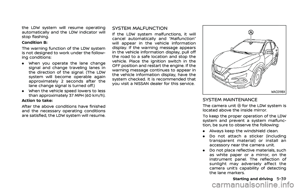
The camera unitfor the LDW system is
located above the inside mirror.
To keep the proper operation of the LDW
system and prevent a system malfunc-
tion, be sure to observe the following:
. Always keep the windshield clean.
. Do not attach a sticker (including
transparent material) or install an
accessory near the camera unit.
. Do not place reflective materials, such
as white paper or a mirror, on the
instrument panel. The reflection of
sunlight may adversely affect the
camera unit’s capability of detecting
the lane markers.
Starting and driving5-39
Page 280 of 508
5-40Starting and driving
.Do not strike or damage the areas
around the camera unit. Do not touch
the camera lens or remove the screw
located on the camera unit. If the
camera unit is damaged due to an
accident, it is recommended that you
visit a NISSAN dealer.
WARNING
Failure to follow the warnings and
instructions for proper use of the I-LI
system could result in serious injury
or death.
.The I-LI system will not steer the
vehicle or prevent loss of control.
It is the driver’s responsibility to
stay alert, drive safely, keep the
vehicle in the traveling lane, and
be in control of the vehicle at all
times.
. The I-LI system is primarily in-
tended for use on well-developed
freeways or highways. It may not
detect the lane markers in certain
road, weather, or driving condi-
tions.
WAC0198X
The I-LI system warns the driver if the
vehicle has left the center of the traveling
lane with the I-LI indicator and chime, and
helps assist the driver to return the
vehicle to the center of the traveling lane
by applying the brakes to the left or right
wheels individually (for a short period of
time).
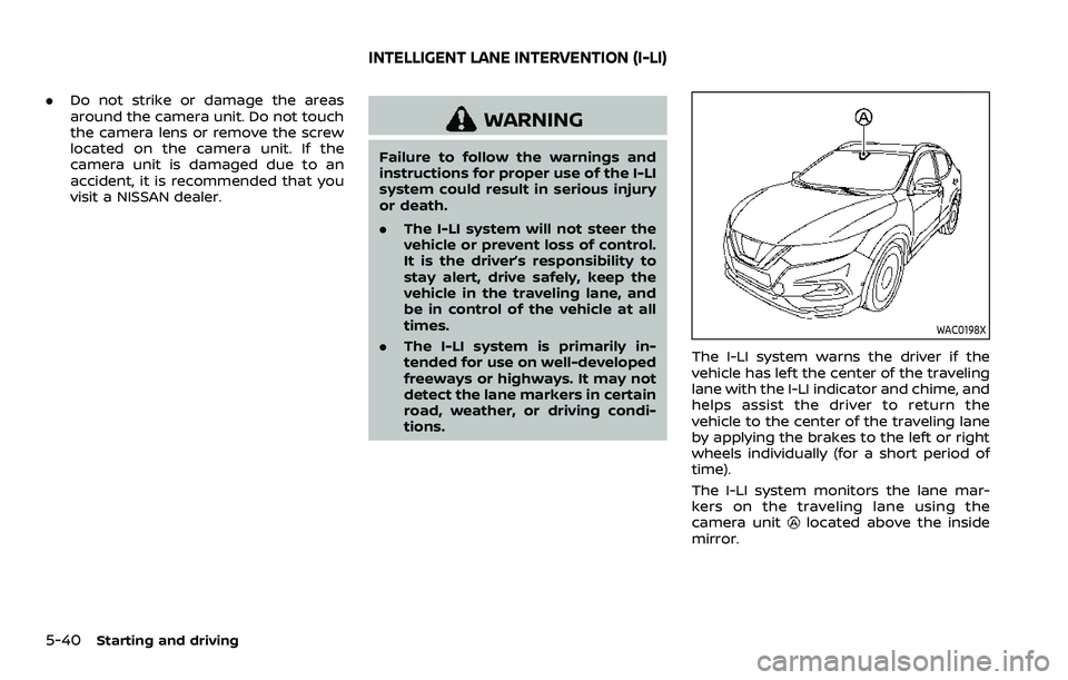
The I-LI system monitors the lane mar-
kers on the traveling lane using the
camera unit
located above the inside
mirror.
INTELLIGENT LANE INTERVENTION (I-LI)
Page 285 of 508
exist, turn off the I-LI system. Push the
dynamic driver assistance switch (models
without ProPILOT assist) or the ProPILOT
assist switch (models with ProPILOT as-
sist) again to turn the I-LI system back on.
Temporary disabled status at high tem-
perature:
If the vehicle is parked in direct sunlight
under high temperature conditions (over
approximately 104°F (40°C)) and then the
I-LI system is turned on, the I-LI system
may be deactivated automatically and
the following message will appear on
the vehicle information display: “Unavail-
able: High Cabin Temperature.” When the
interior temperature is reduced, the sys-
tem will resume operating automatically.
SYSTEM MALFUNCTION
If the I-LI system malfunctions, it will
cancel automatically. The I-LI indicator
(orange) will illuminate and the “Malfunc-
tion” warning message will appear in the
display.
If the I-LI indicator (orange) illuminates in
the display, pull off the road to a safe
location. Turn the engine off and restart
the engine. If the I-LI indicator (orange)
continues to illuminate, have the I-LI
system checked. It is recommended that
you visit a NISSAN dealer for this service.
WAC0198X
SYSTEM MAINTENANCE
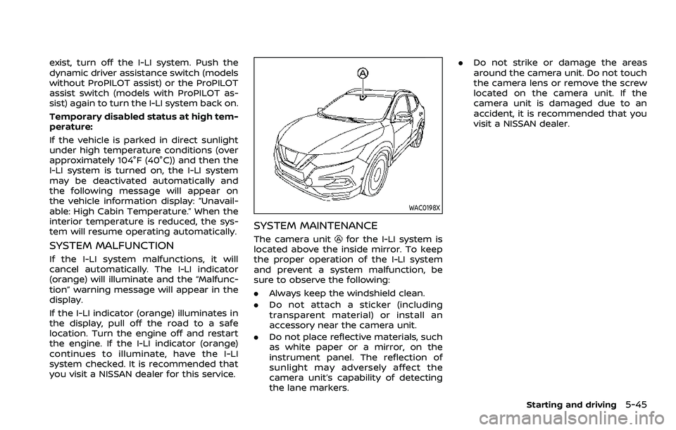
The camera unitfor the I-LI system is
located above the inside mirror. To keep
the proper operation of the I-LI system
and prevent a system malfunction, be
sure to observe the following:
. Always keep the windshield clean.
. Do not attach a sticker (including
transparent material) or install an
accessory near the camera unit.
. Do not place reflective materials, such
as white paper or a mirror, on the
instrument panel. The reflection of
sunlight may adversely affect the
camera unit’s capability of detecting
the lane markers. .
Do not strike or damage the areas
around the camera unit. Do not touch
the camera lens or remove the screw
located on the camera unit. If the
camera unit is damaged due to an
accident, it is recommended that you
visit a NISSAN dealer.
Starting and driving5-45
Page 286 of 508
5-46Starting and driving
WARNING
Failure to follow the warnings and
instructions for proper use of the
BSW system could result in serious
injury or death.
.The BSW system is not a replace-
ment for proper driving proce-
dure and is not designed to
prevent contact with vehicles or
objects. When changing lanes, al-
ways use the side and rear mir-
rors and turn and look in the
direction your vehicle will move
to ensure it is safe to change
lanes. Never rely solely on the
BSW system.
The BSW system helps alert the driver of
other vehicles in adjacent lanes when
changing lanes.
JVS0649X
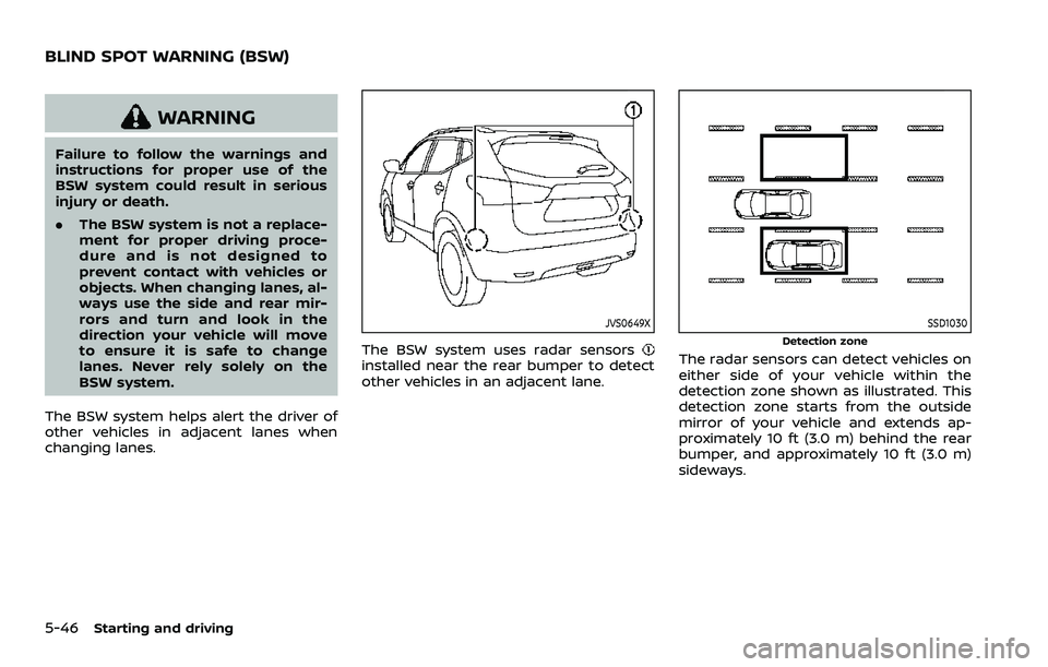
The BSW system uses radar sensorsinstalled near the rear bumper to detect
other vehicles in an adjacent lane.
SSD1030
Detection zone
The radar sensors can detect vehicles on
either side of your vehicle within the
detection zone shown as illustrated. This
detection zone starts from the outside
mirror of your vehicle and extends ap-
proximately 10 ft (3.0 m) behind the rear
bumper, and approximately 10 ft (3.0 m)
sideways.
BLIND SPOT WARNING (BSW)