key NISSAN ROGUE SPORT 2022 Workshop Manual
[x] Cancel search | Manufacturer: NISSAN, Model Year: 2022, Model line: ROGUE SPORT, Model: NISSAN ROGUE SPORT 2022Pages: 508, PDF Size: 2.43 MB
Page 258 of 508
5-18Starting and driving
1. Apply the parking brake.
2.Continuously Variable Transmission
(CVT) model:
Move the shift lever to the P (Park) or N
(Neutral) position. (P is recommended.)
The starter is designed so that it does
not operate unless the shift lever is in
either of the above positions.
Manual Transmission (MT) model:
Move the shift lever to the N (Neutral)
position, and depress the clutch pedal
to the floor while starting the engine.
3. Crank the engine with your foot off
the accelerator pedal by turning the
ignition switch to START. Release the
switch when the engine starts. If the
engine starts, but fails to run, repeat
the above procedure.
.If the engine is very hard to start in
extremely cold weather or when
restarting, depress the accelerator
pedal a little (approximately 1/3 to
the floor) and hold it and then
crank the engine. Release the ac-
celerator pedal when the engine
starts.
.If the engine is very hard to startbecause it is flooded, depress the
accelerator pedal all the way to the
floor and hold it. Crank the engine
for 5 - 6 seconds. After cranking the engine, release the accelerator
pedal. Crank the engine
with your
foot off the accelerator pedal by
turning the ignition switch to
START. Release the ignition switch
when the engine starts. If the
engine starts, but fails to run, re-
peat the above procedure.
CAUTION
Do not operate the starter for more
than 15 seconds at a time. If the
engine does not start, turn the igni-
tion switch off and wait 10 seconds
before cranking again, otherwise the
starter could be damaged.
Do not turn the ignition switch to the
START position unless the engine
and starter have stopped moving.
Attempting to start the engine while
the engine or starter is moving may
cause damage.
4. Warm-up
Allow the engine to idle for at least 30
seconds after starting. Do not race the
engine while warming it up. Drive at
moderate speed for a short distance
first, especially in cold weather. In cold
weather, keep the engine running for a minimum of 2 - 3 minutes before
shutting it off. Starting and stopping
the engine over a short period of time
may make the vehicle more difficult to
start.
5. To stop the engine, shift the shift lever to the P (Park) position (CVT model) or
N (Neutral) position (MT model) and
turn the ignition switch to the OFF
position.
NOTE:
Care should be taken to avoid situations
that can lead to potential battery dis-
charge and potential no-start condi-
tions such as:
1. Installation or extended use of elec-
tronic accessories that consume
battery power when the engine is
not running (Phone chargers, GPS,
DVD players, etc.)
2. Vehicle is not driven regularly and/
or only driven short distances.
In these cases, the battery may need to
be charged to maintain battery health.
STARTING THE ENGINE (model
without Intelligent Key system)
Page 259 of 508
1. Apply the parking brake.
2.Continuously Variable Transmission
(CVT) model:
Move the shift lever to the P (Park) or N
(Neutral) position. (P is recommended.)
The starter is designed not to operate
unless the shift lever is in either of the
above positions.
Manual Transmission (MT) model:
Move the shift lever to the N (Neutral)
position. Depress the clutch pedal fully
to the floor.
The starter is designed not to operate
unless the clutch pedal is fully de-
pressed.
The Intelligent Key must be carried
when operating the ignition switch.
3. Push the ignition switch to the ON position. Depress the brake pedal (CVT
models) or the clutch pedal (MT mod-
els) and push the ignition switch to
start the engine.
To start the engine immediately, push
and release the ignition switch while
depressing the brake pedal (CVT mod-
els) or the clutch pedal (MT models)
with the ignition switch in any posi-
tion.
.If the engine is very hard to start in
extremely cold weather or when restarting, depress the accelerator
pedal a little (approximately 1/3 to
the floor) and while holding, crank
the engine. Release the accelerator
pedal when the engine starts.
.If the engine is very hard to start
because it is flooded, depress the
accelerator pedal all the way to the
floor and hold it. Push the ignition
switch to the ON position to start
cranking the engine. After 5 or 6
seconds, stop cranking by pushing
the ignition switch to OFF. After
cranking the engine, release the
accelerator pedal. Crank the engine
with your foot off the accelerator
pedal by depressing the brake
pedal and pushing the push-button
ignition switch to start the engine.
If the engine starts, but fails to run,
repeat the above procedure.
CAUTION
Do not operate the starter for more
than 15 seconds at a time. If the
engine does not start, push the
ignition switch to OFF and wait 10
seconds before cranking again,
otherwise the starter could be da-
maged. 4.
Warm-up
Allow the engine to idle for at least 30
seconds after starting. Do not race the
engine while warming it up. Drive at
moderate speed for a short distance
first, especially in cold weather. In cold
weather, keep the engine running for
a minimum of 2 - 3 minutes before
shutting it off. Starting and stopping
the engine over a short period of time
may make the vehicle more difficult to
start.
When racing the engine up to 4,000
rpm or more under no load condition,
the engine will enter the fuel cut
mode.
5. To stop the engine, move the shift lever to the P (Park) position (CVT
models) or move the shift lever to
the N (Neutral) position (MT models),
and push the ignition switch to the
OFF position.
NOTE:
Care should be taken to avoid situations
that can lead to potential battery dis-
charge and potential no-start condi-
tions such as:
1. Installation or extended use of elec-
tronic accessories that consume
battery power when the engine is
not running (Phone chargers, GPS,
DVD players, etc.)
Starting and driving5-19
STARTING THE ENGINE (model
with Intelligent Key system)
Page 260 of 508
5-20Starting and driving
2.Vehicle is not driven regularly and/
or only driven short distances.
In these cases, the battery may need to
be charged to maintain battery health.
REMOTE ENGINE START (if so
equipped)
Vehicles started with the remote engine
start function require the ignition switch
to be placed in the ON position before the
shift lever can be moved from the P (Park)
position. To place the ignition switch in
the ON position, perform the following
steps:
1. Make sure that the Intelligent Key is carried with you.
2. Depress the brake pedal.
3. Push the ignition switch once to the ON position.
For additional information about the
remote engine start function, see “Re-
mote engine start” (P.3-23).
CONTINUOUSLY VARIABLE TRANS-
MISSION (CVT)
The Continuously Variable Transmission
(CVT) in your vehicle is electronically
controlled to produce maximum power
and smooth operation.
The recommended operating procedures
for this transmission are shown on the
following pages. Follow these procedures
for maximum vehicle performance and
driving enjoyment.
Engine power may be automatically
reduced to protect the CVT if the engine
speed increases quickly when driving
on slippery roads or while being tested
on some dynamometers.
Starting the vehicle
1. After starting the engine, fully depress the foot brake pedal before moving
the shift lever out of the P (Park)
position.
This CVT is designed so that the foot
brake pedal must be depressed
before shifting from P (Park) to any
driving position while the ignition
switch is in the ON position.
The shift lever cannot be moved out
of the P (Park) position and into any
of the other positions if the ignition
switch is placed in the LOCK or OFF position.
2. Keep the foot brake pedal depressed and move the shift lever to a driving
position.
3. Release the parking brake and foot brake pedal, and then gradually start
the vehicle in motion.
WARNING
.Do not depress the accelerator
pedal while shifting from P (Park)
or N (Neutral) to R (Reverse), D
(Drive), or manual shift mode. Al-
ways depress the brake pedal
until shifting is completed. Failure
to do so could cause you to lose
control and have an accident.
. Cold engine idle speed is high, so
use caution when shifting into a
forward or reverse gear before
the engine has warmed up.
. Never shift to either the P (Park)
or R (Reverse) position while ve-
hicle is moving forward and P
(Park) or D (Drive) while the vehi-
cle is reversing. This could cause
an accident or damage the trans-
mission.
DRIVING THE VEHICLE
Page 265 of 508
4. Insert the mechanical key and pushdown the shift lock release.
5. Push the shift lever button and move the shift lever to the N (Neutral)
position while holding down the shift
lock release.
Place the ignition switch in the ON posi-
tion. The vehicle may be moved to the
desired location.
Replace the removed shift lock release
cover after the operation.
If the shift lever cannot be moved out of
the P (Park) position, have the CVT system
checked as soon as possible. It is recom-
mended you visit a NISSAN dealer for this
service.
WARNING
If the shift lever cannot be moved
from the P (Park) position while the
engine is running and the brake
pedal is depressed, the stop lights
may not work. Malfunctioning stop
lights could cause an accident injur-
ing yourself and others.
MANUAL TRANSMISSION (MT)
WARNING
. Do not downshift abruptly on
slippery roads. This may cause a
loss of control.
. Do not over-rev the engine when
shifting to a lower gear. This may
cause a loss of control or engine
damage.
. When the high fluid temperature
protection mode or fail-safe op-
eration occurs, vehicle speed may
be gradually reduced. The re-
duced speed may be lower than
other traffic, which could increase
the chance of a collision. Be
especially careful when driving. If
necessary, pull to the side of the
road at a safe place and allow the
transmission to return to normal
operation, or have it repaired if
necessary.
CAUTION
.Do not rest your foot on the
clutch pedal while driving. This may damage the clutch.
. Fully depress the clutch pedal
before shifting to help prevent
transmission damage.
. Stop your vehicle completely be-
fore shifting into R (Reverse).
. When the vehicle is stopped for a
period of time, for example at a
stop light, shift to N (Neutral) and
release the clutch pedal with the
foot brake applied.
Starting and driving5-25
Page 368 of 508
5-128Starting and driving
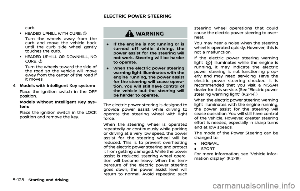
curb..HEADED UPHILL WITH CURB:
Turn the wheels away from the
curb and move the vehicle back
until the curb side wheel gently
touches the curb.
.HEADED UPHILL OR DOWNHILL, NOCURB:
Turn the wheels toward the side of
the road so the vehicle will move
away from the center of the road if
it moves.
4. Models with Intelligent Key system:
Place the ignition switch in the OFF
position.
Models without Intelligent Key sys-
tem:
Place the ignition switch in the LOCK
position and remove the key.
WARNING
.If the engine is not running or is
turned off while driving, the
power assist for the steering will
not work. Steering will be harder
to operate.
. When the electric power steering
warning light illuminates with the
engine running, the power assist
for the steering will cease opera-
tion. You will still have control of
the vehicle but the steering will
be harder to operate.
The electric power steering is designed to
provide power assist while driving to
operate the steering wheel with light
force.
When the steering wheel is operated
repeatedly or continuously while parking
or driving at a very low speed, the power
assist for the steering wheel will be
reduced. This is to prevent overheating
of the electric power steering and protect
it from getting damaged. While the power
assist is reduced, steering wheel opera-
tion will become heavy. When the tem-
perature of the electric power steering
goes down, the power assist level will
return to normal. Avoid repeating such steering wheel operations that could
cause the electric power steering to over-
heat.
You may hear a noise when the steering
wheel is operated quickly. However, this is
not a malfunction.
If the electric power steering warning
light
illuminates while the engine is
running, it may indicate the electric
power steering is not functioning prop-
erly and may need servicing. Have the
electric power steering checked. It is
recommended that you visit a NISSAN
dealer for this service. (See “Electric power
steering warning light” (P.2-14).)
When the electric power steering warning
light illuminates with the engine running,
the power assist for the steering will
cease operation. You will still have control
of the vehicle. However, greater steering
effort is needed, especially in sharp turns
and at low speeds.
The mode of the Power Steering can be
changed to:
. NORMAL
. SPORT
For more information, see “Vehicle infor-
mation display” (P.2-19).
ELECTRIC POWER STEERING
Page 376 of 508
5-136Starting and driving
WARNING
.Never rely solely on the hill start
assist system to prevent the ve-
hicle from moving backward on a
hill. Always drive carefully and
attentively. Depress the brake
pedal when the vehicle is stopped
on a steep hill. Be especially care-
ful when stopped on a hill on
frozen or muddy roads. Failure
to prevent the vehicle from rolling
backwards may result in a loss of
control of the vehicle and possi-
ble serious injury or death.
. The hill start assist system is not
designed to hold the vehicle at a
standstill on a hill. Depress the
brake pedal when the vehicle is
stopped on a steep hill. Failure to
do so may cause the vehicle to
roll backwards and may result in
a collision or serious personal
injury.
. The hill start assist system may
not prevent the vehicle from roll-
ing backwards on a hill under all
load or road conditions. Always
be prepared to depress the brake
pedal to prevent the vehicle from
rolling backwards. Failure to do so may result in a collision or
serious personal injury.
The hill start assist system automatically
keeps the brakes applied to help prevent
the vehicle from rolling backwards in the
time it takes the driver to release the
brake pedal and apply the accelerator
when the vehicle is stopped on a hill.
The hill start assist system will operate
automatically under the following condi-
tions:
. The transmission is shifted to a for-
ward or reverse gear.
. The vehicle is stopped completely on a
hill by applying the brake.
The maximum holding time is 2 seconds.
After 2 seconds the vehicle will begin to
roll back and the hill start assist system
will stop operating completely.
The hill start assist system will not
operate when the transmission is shifted
to the N (Neutral) or P (Park) position (CVT
models) or on a flat and level road.
When the Vehicle Dynamic Control (VDC)
warning light illuminates in the meter, the
hill start assist system will not operate.
(See “Vehicle Dynamic Control (VDC)
warning light” (P.2-17).)
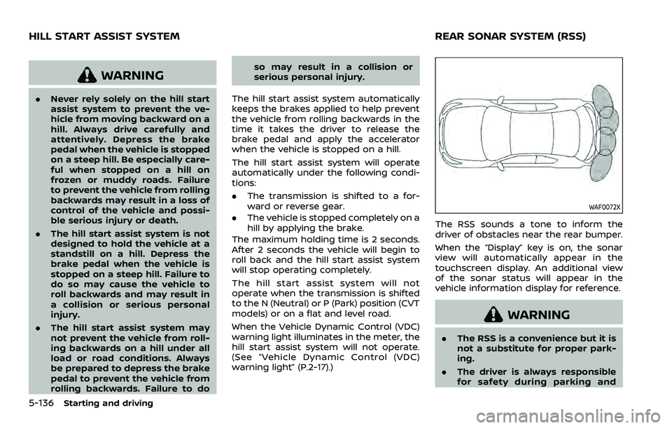
WAF0072X
The RSS sounds a tone to inform the
driver of obstacles near the rear bumper.
When the “Display” key is on, the sonar
view will automatically appear in the
touchscreen display. An additional view
of the sonar status will appear in the
vehicle information display for reference.
WARNING
. The RSS is a convenience but it is
not a substitute for proper park-
ing.
. The driver is always responsible
for safety during parking and
HILL START ASSIST SYSTEM REAR SONAR SYSTEM (RSS)
Page 381 of 508
Action to take:
When the above conditions no longer
exist, the system will resume automati-
cally.
SYSTEM MAINTENANCE
The sonar sensors are located on the rear
bumpers. (See “Exterior rear” (P.0-4).)
.Always keep the area near the sonar
sensors clean.
. If the sonar sensors are dirty, wipe
them off with a soft cloth while being
careful to not damage them.
. The sonar sensors may be blocked by
temporary ambient conditions such
as splashing water, mist or fog. The
blocked condition may also be caused
by objects such as ice, frost or dirt
obstructing the sonar sensors. Check
for and remove objects obstructing
the area around the sonar sensors.
. Do not subject the area around the
sonar sensors to strong impact. Also,
do not remove or disassemble the
sonar sensors. If the sonar sensors
and peripheral areas are deformed in
an accident, etc., have the sonar
sensors checked by a NISSAN dealer.
. Do not attach stickers (including
transparent material), install acces-
sories or apply additional paint on
the sonar sensors and their surround- ing areas. This may cause a malfunc-
tion or improper operation.
. When washing the vehicle using a
high-pressure washer, do not apply
direct washer pressure on the sonar
sensors. This may cause a malfunction
of the sonar sensors.
FREEING A FROZEN DOOR LOCK
To prevent a door lock from freezing,
apply deicer through the key hole. If the
lock becomes frozen, heat the key before
inserting it into the key hole, or use the
Intelligent Key system or the remote
keyless entry key fob.
ANTI-FREEZE
In the winter when it is anticipated that
the outside temperature will drop below
32°F (0°C), check the anti-freeze to assure
proper winter protection. For additional
information, see “Engine cooling system”
(P.8-4).
BATTERY
If the battery is not fully charged during
extremely cold weather conditions, the
battery fluid may freeze and damage the
battery. To maintain maximum efficiency,
the battery should be checked regularly.
For additional information, see “Battery”
(P.8-11).
DRAINING OF COOLANT WATER
If the vehicle is to be left outside without
anti-freeze, drain the cooling system,
including the engine block. Refill before
operating the vehicle. For details, see
“Engine cooling system” (P.8-4).
Starting and driving5-141
COLD WEATHER DRIVING
Page 413 of 508
8 Do-it-yourself
Maintenance precautions ...................................................... 8-2
Engine compartment check locations ........................ 8-3MR20DD engine model ..................................................... 8-4
Engine cooling system ............................................................. 8-4 Checking engine coolant level .................................... 8-5
Changing engine coolant ................................................ 8-6
Engine oil ........................................................................\
..................... 8-6 Checking engine oil level ................................................. 8-6
Changing engine oil and filter ..................................... 8-6
Continuously Variable Transmission
(CVT) fluid ........................................................................\
.................... 8-9
Brake and clutch (if so equipped) fluid ....................... 8-9
Window washer fluid .............................................................. 8-10
Battery ........................................................................\
........................ 8-11 Jump starting ........................................................................\
. 8-12
Variable voltage control system ................................... 8-13
Drive belt ........................................................................\
.................. 8-13
Spark plugs ........................................................................\
............. 8-14 Replacing spark plugs ..................................................... 8-14
Air cleaner ........................................................................\
............... 8-15
Air duct removal .................................................................. 8-15
Air cleaner filter replacement ................................... 8-15 Windshield wiper blades ..................................................... 8-16
Cleaning ........................................................................\
........... 8-16
Replacing ........................................................................\
........ 8-16
Rear window wiper blade .................................................. 8-17
Brakes ........................................................................\
........................ 8-17 Self-adjusting brakes ..................................................... 8-17
Brake pad wear warning ............................................ 8-17
Fuses ........................................................................\
........................... 8-18 Engine compartment .................................................... 8-18
Passenger compartment ........................................... 8-20
Key fob battery replacement .......................................... 8-21
Intelligent Key battery replacement .......................... 8-23
Lights ........................................................................\
.......................... 8-25 Headlights ........................................................................\
...... 8-25
Exterior and interior lights ........................................ 8-27
Wheels and tires ........................................................................\
8-29
Tire pressure ........................................................................\
8-29
Tire labeling ........................................................................\
.. 8-33
Types of tires ....................................................................... 8-35
Tire chains ........................................................................\
...... 8-36
Changing wheels and tires ...................................... 8-37
Page 415 of 508
off and wait until it cools down.
. Avoid direct contact with used
engine oil and coolant. Impro-
perly disposed engine oil, and
engine coolant and/or other ve-
hicle fluids can damage the en-
vironment. Always conform to
local regulations for disposal of
vehicle fluid.
. Never leave the engine or the CVT
related component harnesses
disconnected while the ignition
switch is in the ON position.
. Never connect or disconnect the
battery or any transistorized
component while the ignition
switch is in the ON position.
. Your vehicle is equipped with an
automatic engine cooling fan. It
may come on at any time without
warning, even if the ignition key is
in the OFF position and the en-
gine is not running. To avoid
injury, always disconnect the ne-
gative battery cable before work-
ing near the fan.
This “8. Do-it-yourself” section gives in-
structions regarding only those items
which are relatively easy for an owner to
perform. A genuine NISSAN Service Manual is also
available. (See “Owner’s manual/service
manual order information” (P.10-21).)
You should be aware that incomplete or
improper servicing may result in operat-
ing difficulties or excessive emissions, and
could affect your warranty coverage.
If in
doubt about any servicing, it is recom-
mended you have it done by a NISSAN
dealer.
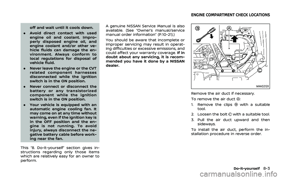
WAA0212X
Remove the air duct if necessary.
To remove the air duct
:
1. Remove the clips
with a suitable
tool.
2. Loosen the bolt
with a suitable tool.
3. Pull the air duct upward and then sideways.
To install the air duct, perform the in-
stallation procedure in reverse order.
Do-it-yourself8-3
ENGINE COMPARTMENT CHECK LOCATIONS
Page 433 of 508

JVM0415X
Extended storage fuse switch (if so
equipped)
To reduce battery drain, the extended
storage fuse switch comes from the
factory switched off. Prior to delivery of
your vehicle, the switch is pushed in
(switched on) and should always remain
on.
If the extended storage fuse switch is not
pushed in (switched on), the meter may
display a warning message. See “21. Ship-
ping Mode On Push Storage Fuse warn-
ing” (P.2-33).
If any electrical equipment does not
operate, remove the extended storage
fuse switch and check for an open fuse.NOTE:
If the extended storage fuse switch
malfunctions or if the fuse is open, it is
not necessary to replace the switch. In
this case, remove the extended storage
fuse switch and replace it with a new
fuse of the same rating.
How to remove the extended storage
fuse switch:
1. To remove the extended storage fuse
switch, be sure the ignition switch is in
the OFF or LOCK position.
2. Be sure the headlights are off. (See “Headlight switch” (P.2-52) or “Intelli-
gent Auto Headlight system” (P.2-52).)
3. Remove the fuse box cover.
4. Pinch the locking tabs
found on
each side of the extended storage
fuse switch.
5. Pull the extended storage fuse switch straight out from the fuse box
.
CAUTION
.Be careful not to allow children to
swallow the battery and removed
parts.
. An improperly disposed battery
can harm the environment. Al-
ways confirm local regulations
for battery disposal.
. When changing batteries, do not
let dust or oil get on the compo-
nents.
. There is danger of explosion if the
lithium battery is incorrectly re-
placed. Replace only with the
same or equivalent type.
Do-it-yourself8-21
KEY FOB BATTERY REPLACEMENT